
Related Manuals for Emerson Rosemount 3308 Series


Summary of Contents for Emerson Rosemount 3308 Series
- Page 1 Reference Manual 00809-0100-4308, Rev CD February 2020 ™ Rosemount 3308 Series Wireless Guided Wave Radar, 3308A...
- Page 2 Equipment service needs. • 1-800-654-7768 (24 hours a day — includes Canada) • Outside of these areas, contact your local Emerson representative. NOTICE Power module considerations. • Each Power Module contains two "C" size primary lithium/thionyl chloride batteries. Each battery contains approximately 2.5 grams of lithium, for a total of 5 grams in each pack.
- Page 3 WARNING Explosions could result in death or serious injury. • Verify that the operating atmosphere of the transmitter is consistent with the appropriate hazardous locations certifications. • Installation of device in an explosive environment must be in accordance with appropriate local, national, and international standards, codes, and practices.
- Page 4 The products described in this document are NOT designed for nuclear-qualified applications. Using non-nuclear qualified products in applications that require nuclear-qualified hardware or products may cause inaccurate readings. For information on Rosemount nuclear-qualified products, contact your local Emerson Sales Representative.
-
Page 5: Table Of Contents
1.1 Using this manual..........................9 1.2 Product recycling/disposal........................9 Chapter 2 Transmitter overview....................11 2.1 Theory of operation........................11 2.2 Measuring range..........................14 2.3 Emerson Wireless........................... 15 2.4 Application characteristics......................15 2.5 Application examples........................17 2.6 Components of the transmitter...................... 18 2.7 Probe selection guide........................20 Chapter 3 Installation........................23... - Page 6 B.14 Approval drawings........................192 Appendix C High gain remote antenna option................195 C.1 Safety messages...........................195 C.2 Functional and physical specifications..................195 C.3 Review installation considerations....................196 C.4 Transient/lightning considerations....................197 C.5 Install the high gain remote antenna.................... 197 Appendix D Configuration parameters..................201 Rosemount 3308 Series...
- Page 7 Reference Manual Contents 00809-0100-4308 February 2020 D.1 Menu overview of the Device Descriptor (DD)................201 D.2 Configuration parameters......................202 Appendix E Alert message mapping....................223 E.1 Alert messages and descriptions....................223 Reference Manual...
- Page 8 Contents Reference Manual February 2020 00809-0100-4308 viii Rosemount 3308 Series...
-
Page 9: Chapter 1 Introduction
Alert message mapping outlines the most important alerts in the HART command 48 Additional Status Field for Rosemount 3308 Series. Product recycling/disposal Recycling of equipment and packaging should be taken into consideration and disposed of in accordance with local and national legislation or regulations. - Page 10 Introduction Reference Manual February 2020 00809-0100-4308 Rosemount 3308 Series...
-
Page 11: Chapter 2 Transmitter Overview
Reference Manual Transmitter overview 00809-0100-4308 February 2020 Transmitter overview Theory of operation ™ The Rosemount 3308 Series is the first true wireless level transmitter that is based on the Time Domain Reflectometry (TDR) principle. Low power nano-second-pulses are guided along a probe submerged in the process media. When a pulse reaches the surface of the material it is measuring, part of the energy is reflected back to the transmitter, and the time difference between the generated and reflected pulse is converted into a distance from which the total level or interface level is calculated (see... - Page 12 This peak indicates the interface level. The peak is caused by reflection from the interface between an upper product and a bottom product with a relatively high dielectric constant. This peak is identified when the measurement mode is set to Product Level and Interface Level or Interface Level with Submerged Probe. Rosemount 3308 Series...
- Page 13 Reference Manual Transmitter overview 00809-0100-4308 February 2020 2.1.4 Probe end peak It is caused by reflection from the probe end. If the probe is grounded, the peak will be positive. If the probe end is submerged in a high dielectric media, such as water, it will not be visible.
-
Page 14: Measuring Range
Note Measurements may not be possible in the Blind Zones, and measurements close to the Blind Zones will have reduced accuracy. Therefore, the alarm points should be configured outside these zones. Related information Accuracy over measuring range Rosemount 3308 Series... -
Page 15: Emerson Wireless
The transmitter handles flat or dish-bottom tanks equally well. 2.4.2 In-tank obstructions The Rosemount 3308 Series Transmitter is relatively insensitive to objects in the tank since the radar signal is transmitted along a probe. Reference Manual... - Page 16 (flexible probes only) or fix/guide the probe to the tank bottom. 2.4.3 Interface level measurement Rosemount 3308 Series Transmitter is well suited for measuring the interface of oil and water, or other liquids with significant dielectric differences. Figure 2-6: Interface Level Measurement A.
-
Page 17: Application Examples
Storage and buffer tanks The Rosemount 3308 Series Transmitter is ideal for storage or buffer tanks for almost any liquid, such as oil, gas condensate, water, or chemicals. Low pressure separators The Rosemount 3308 Series Transmitter can measure both level and interface level, such as for separator applications. -
Page 18: Components Of The Transmitter
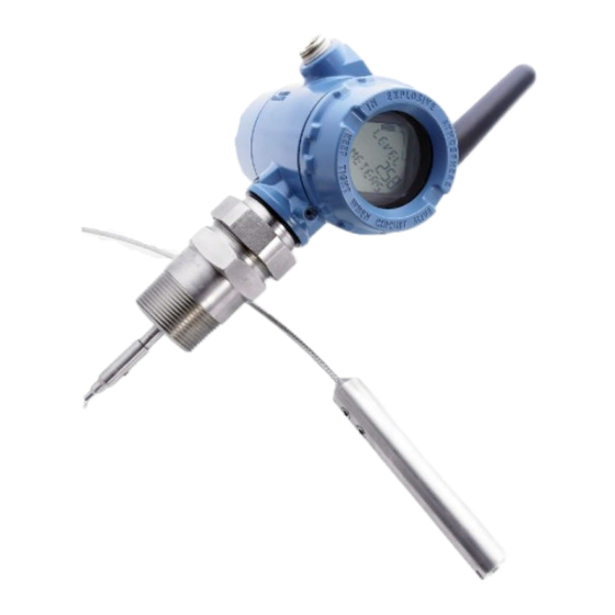
February 2020 00809-0100-4308 Open applications —ponds, basins, sumps The Rosemount 3308 Series Transmitter can be installed in open air to measure liquids not contained in a tank. Chamber applications The Rosemount 3308 Series Transmitter is a good choice for both chamber and pipe installations. - Page 19 Reference Manual Transmitter overview 00809-0100-4308 February 2020 Figure 2-7: Transmitter Components A. Radar electronics B. Flanged process connections C. Probe D. Dual compartment housing E. Threaded process connections F. BSPP (G) G. NPT H. Flexible single lead with weight I. Rigid single lead J.
-
Page 20: Probe Selection Guide
Transmitter overview Reference Manual February 2020 00809-0100-4308 Probe selection guide Use the following guidelines to choose appropriate probe for your Rosemount 3308 Series transmitter: Table 2-1: Probe Selection Guide G=Good, NR=Not Recommended, AD=Application Dependent (consult factory) Flexible single lead Rigid single lead,... - Page 21 Reference Manual Transmitter overview 00809-0100-4308 February 2020 Table 2-1: Probe Selection Guide (continued) Flexible single lead Rigid single lead, Flexible twin lead Coaxial segmented rigid single lead Tank environment considerations Probe is close (<12 in./30 cm) to disturbing objects Tall and narrow mounting nozzles (diameter <6 in./15 cm and...
- Page 22 Transmitter overview Reference Manual February 2020 00809-0100-4308 Rosemount 3308 Series...
-
Page 23: Chapter 3 Installation
Reference Manual Installation 00809-0100-4308 February 2020 Installation Safety messages Instructions and procedures in this section may require special precautions to ensure the safety of the personnel performing the operations. Information that potentially raises safety issues is indicated by a warning symbol ( ). -
Page 24: Installation Procedure
5. Install the power module. 6. Position the antenna. 7. Utilize the display. Review mounting considerations Before installing the Rosemount 3308 Series Transmitter, consider recommendations for sufficient free space, mounting position, and special needs for non-metallic tanks. 3.3.1 Recommended mounting position for liquids When finding an appropriate mounting position for the transmitter, the conditions of the tank must be carefully considered. - Page 25 Reference Manual Installation 00809-0100-4308 February 2020 Figure 3-1: Mounting Position A. Inlet pipe B. Agitator C. Heating coils The following guidelines should be considered when mounting the transmitter: • Do not mount close to inlet pipes. • Do not mount close to agitators. If the probe can move to within 12 in. (30 cm) away from an agitator, the probe should be anchored.
- Page 26 16 in. (400 mm) Plastic, concrete or rugged metal tank wall Coaxial 0 in. (0 mm) Flexible twin 4 in. (100 mm) Minimum clearance from tank bottom for the coaxial and rigid single probes is 0.2 in. (5 mm). Rosemount 3308 Series...
- Page 27 Reference Manual Installation 00809-0100-4308 February 2020 3.3.3 Flange connection on nozzles Figure 3-3: Mounting in Nozzles A. Maximum nozzle height B. Minimum nozzle diameter C. Confirm the nozzle does not extend into the tank. The transmitter can be mounted in nozzles by using an appropriate flange. It is recommended that the nozzle size is within the dimensions given in Table 3-2.
- Page 28 Minimum diameter Rigid single/segmented rigid 3 or 4 in. (75 or 100 mm) 2 in. (50 mm) single Flexible single 4 in. (100 mm) Consult your local Emerson representative Flexible twin 4 in. (100 mm) Consult your local Emerson representative Coaxial 3 or 4 in.
- Page 29 Use a centering disc the same diameter as the chamber if the probe length >3.3 ft. (1 m). Table 3-8 for which disc to use. Existing chamber A Rosemount 3308 Series Transmitter is the perfect replacement in an existing displacer chamber. Proprietary flanges are offered, enabling use of existing chambers to make installation easy. Reference Manual...
- Page 30 C. Displacer length Considerations when changing to Rosemount 3308 Series: • The Rosemount 3308 Series flange choice and probe length must be correctly matched to the chamber. Both standard ASME and EN (DIN), as well as proprietary chamber flanges, are available. See Proprietary flanges to identify the proprietary flanges.
- Page 31 Reference Manual Installation 00809-0100-4308 February 2020 The probe length determines if a single rigid or single flexible probe should be used: • Less than 19.7 ft. (6.0 m): Rigid single probe is recommended. Use a centering disc for probe > 3.3 ft. (1 m). When mounting space is limited, use a flexible single probe with a weight and centering disc.
-
Page 32: Review Mounting Preparations
5.2 ft. (1.6 m) Water (DC = 80) 3.3 ft. (1.0 m) Review mounting preparations 3.4.1 Measure tank height The Tank Height is defined as the measured distance from the Upper Reference Point to the Zero Reference Point. Rosemount 3308 Series... - Page 33 Reference Manual Installation 00809-0100-4308 February 2020 Figure 3-9: Measure Tank Height A. Upper Reference Point B. Tank Height C. Zero Reference Point 3.4.2 Shorten the probe In order to leave some clearance distance between the probe end and the tank bottom, the probe might have to be shortened.
- Page 34 Figure 3-10: Calculate Probe Length A. Probe Length B. 2 in. (5 cm) clearance Shorten the flexible single/twin lead probe Prerequisites Note The PTFE covered probes must not be cut in field. Procedure 1. Mark where to cut the probe. Rosemount 3308 Series...
- Page 35 Reference Manual Installation 00809-0100-4308 February 2020 2. Remove enough spacers to make place for the weight (only flexible twin lead probes). 3. Loosen the weight. 4. Slide the weight up. Reference Manual...
- Page 36 After shortening the probe be sure to update the transmitter configuration to the new probe length. Related information Probe length Shorten the rigid single lead probe Prerequisites The minimum probe length is 15.7 in. (400 mm). Note The PTFE covered probes must not be cut in field. Rosemount 3308 Series...
- Page 37 Reference Manual Installation 00809-0100-4308 February 2020 Note Ensure the lead is fixed while cutting. Procedure 1. Mark where to cut the probe. 2. Cut the probe at the mark. Postrequisites After shortening the probe be sure to update the transmitter configuration to the new probe length.
- Page 38 Pipes longer than 49 in. (1250 mm) can be shortened by as much as 23.6 in. (600 mm). • Pipes shorter than 49 in. (1250 mm) can be cut as long as the remaining length is not less than 15.7 in. (400 mm). Rosemount 3308 Series...
-
Page 39: Centering Disc For Pipe Installations
Reference Manual Installation 00809-0100-4308 February 2020 2. Insert the centering piece. The centering piece is delivered from factory and should be used to prevent the spacers centering the rod from coming loose. 3. Cut the tube to the desired length. 4. - Page 40 3-in. 3-in. 2-in. 4-in. 4-in. 4-in. 4-in. 3-in. 5-in. 4-in. 4-in. 4-in. 4-in. 6-in. 6-in. 6-in. 4-in. 4-in. 7-in. 6-in. 8-in. 8-in. 8-in. 6-in. 6-in. Schedule is not available for pipe size. No centering disc is available. Rosemount 3308 Series...
- Page 41 Reference Manual Installation 00809-0100-4308 February 2020 3.5.1 Mount a centering disc on flexible single/twin lead probe Procedure 1. Mount the centering disc at the end of the weight. 13 mm 2. Secure the bolt by folding the tab washer. 3.5.2 Mount a centering disc on rigid single lead probe (8 mm) Note Centering discs shall not be used with PTFE covered probes.
- Page 42 Note Do not mount the washer (A) if the centering disc material is PTFE, Alloy C-276, Duplex 2205, or Alloy 400. 3. Insert the split pin through the bushing and the probe. 4. Secure the split pin. Rosemount 3308 Series...
- Page 43 Reference Manual Installation 00809-0100-4308 February 2020 3.5.3 Mount a centering disc on rigid single lead probe (13 Procedure 1. Drill two holes using the drilling fixture (included in your shipment). 2. Mount the bushings and centering disc at the probe end. 3.
-
Page 44: Anchor The Probe
3 mm 4 mm wire, Duplex 1.8 ft-lb (2.5 Nm) 3 mm 2205 The length of the loop will add to the Blind Zone. The location of the chuck will determine the beginning of the Blind Zone. Rosemount 3308 Series... - Page 45 Reference Manual Installation 00809-0100-4308 February 2020 The Probe Length should be configured as the distance from the Upper Reference Point to the top of the chuck. Figure 3-13: Flexible Single Lead Probe with Chuck A ring (customer supplied) can be attached to the weight in a threaded (M8x14) hole at the end of the weight.
- Page 46 The coaxial probe can be secured to the tank wall by fixtures fastened to the tank wall. Fixtures are customer supplied. Ensure the probe can move freely due to thermal expansion without getting stuck in the fixture. Rosemount 3308 Series...
-
Page 47: Mount Device On Tank
Reference Manual Installation 00809-0100-4308 February 2020 Figure 3-17: Coaxial Probe Secured to the Tank Wall A. Ø 1.1 in. (28 mm) The coaxial probe can be guided by a tube welded on the tank bottom. Tubes are customer supplied. Ensure that the probe can move freely in order to handle thermal expansion. - Page 48 1. For adapters with BSPP (G) threads, place a suitable gasket on top of the tank flange. 2. For adapters with NPT threads, use anti-seize paste or PTFE tape according to your site procedures. 3. Lower the transmitter and probe into the tank. Rosemount 3308 Series...
- Page 49 Reference Manual Installation 00809-0100-4308 February 2020 4. Loosen the nut that connects the transmitter head to the probe slightly. 60 mm 5. Screw the adapter into the process connection. 52 mm / 60 mm 6. Rotate the transmitter head so the device display faces the desired direction. 7.
- Page 50 1. Place a suitable gasket on top of the tank flange. Note Gasket should not be used for PTFE covered probe with protective plate. A. PTFE covered probe with protective plate 2. Lower the transmitter and probe with flange into the tank. Rosemount 3308 Series...
- Page 51 Reference Manual Installation 00809-0100-4308 February 2020 3. Tighten bolts and nuts with sufficient torque for the flange and gasket choice. 4. Loosen the nut that connects the transmitter head to the probe slightly. 60 mm 5. Rotate the transmitter head so the device display faces the desired direction. Reference Manual...
- Page 52 PTFE covered probes must be handled carefully to prevent damage to the coating. Procedure 1. Mount the flange on the probe and tighten the flange nut. 60 mm 2. Place a suitable gasket on top of the tank flange. Rosemount 3308 Series...
- Page 53 Reference Manual Installation 00809-0100-4308 February 2020 3. Lower the probe with flange into the tank. 4. Tighten bolts and nuts with sufficient torque for the flange and gasket choice. 5. Mount the transmitter head. Torque 30 Lbft (40 Nm) 60 mm Postrequisites Continue with the grounding step.
- Page 54 A. Horizontal pipe B. Vertical pipe On wall: 2. Mount the transmitter with probe to the bracket. ® 3.7.5 Tank connection with Tri-Clamp Prerequisites Note PTFE covered probes must be handled carefully to prevent damage to the coating. Rosemount 3308 Series...
- Page 55 Reference Manual Installation 00809-0100-4308 February 2020 Procedure 1. Place a suitable gasket on top of the tank flange. 2. Lower the transmitter and probe into the tank. 3. Tighten the clamp to the recommended torque (see the manufacturer’s instruction manual). 4.
- Page 56 Installation Reference Manual February 2020 00809-0100-4308 5. Rotate the transmitter head so the device display faces the desired direction. 6. Tighten the nut. Torque 30 Lbft (40 Nm) 60 mm Postrequisites Continue with the grounding step. Rosemount 3308 Series...
- Page 57 Reference Manual Installation 00809-0100-4308 February 2020 3.7.6 Segmented probe Segmented probe parts Figure 3-19: Segmented Probe Parts 15.2 (385) 31.5 (800) A. Safety ring B. Screw C. Top segment D. Split pin E. PTFE washer (optional) F. Centering disc in PTFE (optional) G.
- Page 58 Also, the bottom segment may need to be shortened. See Adjust the probe length. Assemble the segmented probe Prerequisites Note If there is enough space beside the tank, the probe can be assembled before inserting it into the tank. Rosemount 3308 Series...
- Page 59 Reference Manual Installation 00809-0100-4308 February 2020 Procedure 1. Insert the stop screw to the top segment. Tighten approximately two turns. 2. Pre-assemble the safety ring. Reference Manual...
- Page 60 Installation Reference Manual February 2020 00809-0100-4308 3. Optional: If ordered, mount the centering disc on the bottom segment of the probe. 4. Insert the support tool. Rosemount 3308 Series...
- Page 61 Reference Manual Installation 00809-0100-4308 February 2020 5. Optional: If ordered, mount the centering disc. • Maximum five pcs/probe • Minimum two segments between each centering disc 6. Mount a middle segment (hand tight). Reference Manual...
- Page 62 Installation Reference Manual February 2020 00809-0100-4308 7. Secure the split pin. 8. Insert the second support tool. Rosemount 3308 Series...
- Page 63 Reference Manual Installation 00809-0100-4308 February 2020 9. Remove the first support tool and lower the probe into the tank. 10. Repeat Step 5-Step 9 until all segments are mounted. Be sure to finish with the top segment of the probe. 11.
- Page 64 For safety reasons, at least two people are needed when mounting the device. Hold the device above the tank. High loads can break the support tool. A. Flange/Tri-Clamp B. Threaded C. Gasket D. Sealant on threads (NPT) E. Gasket (BSPP (G)) Rosemount 3308 Series...
- Page 65 Reference Manual Installation 00809-0100-4308 February 2020 13. Tighten the stop screw and slide the safety ring into the groove. 14. Remove the support tool. Reference Manual...
- Page 66 15. Mount the device on the tank. A. Flange B. Tri-Clamp C. Threaded 16. Rotate the housing to the desired direction. 17. Tighten the nut. Torque 30 Lbft (40 Nm) 60 mm 18. Continue with the grounding step. Rosemount 3308 Series...
- Page 67 Reference Manual Installation 00809-0100-4308 February 2020 Adjust the probe length Procedure 1. Determine L, the desired probe length. L, desired probe length: 2. Determine n, the number of middle segments needed for the desired probe length. Table 3-10. n, number of middle segments: 3.
- Page 68 Installation Reference Manual February 2020 00809-0100-4308 5. Mark where to cut the bottom segment. 6. Cut the bottom segment at the mark. Note Ensure the bottom segment is fixed while cutting. Rosemount 3308 Series...
-
Page 69: Ground The Device
Y = L - 9200 Ground the device The Rosemount 3308 Series Wireless Guided Wave Radar transmitter operates with the housing grounded or floating. Floating systems can cause extra noise that may affect many types of readout devices. If the signal appears noisy or erratic, grounding at a single point may solve the problem. -
Page 70: Install The Power Module
Install the power module Prerequisites CAUTION Use caution when handling the power module, it may be damaged if dropped from heights in excess of 20 ft. (6 m). Rosemount 3308 Series... -
Page 71: Position The Antenna
Reference Manual Installation 00809-0100-4308 February 2020 Procedure ™ 1. Install the Black Power Module, SmartPower Solutions model number 701PBKKF into the transmitter. 2. Close the housing cover and tighten to site or safety specifications. Always ensure a proper seal by tightening the electronics housing covers so that metal touches metal, but do not overtighten. -
Page 72: Utilize The Device Display
Figure 3-23: Device Display A. Display pins B. Black tabs C. Display D. Cover Note If the device display four-pin connector is inadvertently removed from the interface board, carefully reinsert the connector before snapping the device display back into place. Rosemount 3308 Series... - Page 73 Reference Manual Installation 00809-0100-4308 February 2020 3.11.2 Retrofitting If an existing transmitter with no display (flat electronics cover) is to be retrofitted with a new display, order spare part kit number 00753-9004-0001(aluminum display kit) or 00753-9004-0004 (stainless steel display kit). These kits contain an extended cover with a display viewing window, a display board, and a display pin connector.
- Page 74 Installation Reference Manual February 2020 00809-0100-4308 Rosemount 3308 Series...
-
Page 75: Chapter 4 Configuration
Reference Manual Configuration 00809-0100-4308 February 2020 Configuration Overview This chapter provides information about configuration, configuration tools, and configuration parameters. • For a proper configuration, follow the steps listed in Configuration procedure. • The configuration can be performed using one of the described configuration tools: AMS Wireless Configurator or a handheld communicator. - Page 76 • This device must accept any interference received, including interference that may cause undesired operation. • This device must be installed to ensure a minimum antenna separation distance of 8 in. (20 cm) from all persons. Rosemount 3308 Series...
-
Page 77: Configuration Procedure
Verify the latest Device Descriptor (DD) is loaded on your systems to ensure proper communication. Procedure ® 1. Within Table 4-1, use the HART Universal Revision and Device Revision numbers to find the correct DD. 2. Download the latest DD at Emerson.com/DeviceInstallKits. Reference Manual... -
Page 78: Get Started With Your Preferred Configuration Tool
AMS Wireless Configurator (version 12.0 or later is required) The AMS Wireless Configurator is the recommended software tool for the wireless network devices, and is supplied with the Emerson Wireless Gateway. Refer to the AMS Wireless Configurator Manual Supplement for further information. - Page 79 The Device Descriptor (DD) is a configuration tool that is developed to assist the user through the configuration. Prerequisites The Rosemount 3308 Series DD is typically installed together with AMS Wireless ® Configurator. To download the latest HART DD, visit the Emerson Device Install Kit site Emerson.com/DeviceInstallKits...
- Page 80 Handheld communicator This section describes how to prepare the handheld communicator to communicate with a Rosemount 3308 Series Transmitter. The handheld communicator can be used to configure the device with a point-to-point connection. Connect the leads on the handheld communicator to the communication terminals of the device.
-
Page 81: Join Device To Wireless Network
For more information, see the Gateway Reference Manual. Related information Install the power module Startup screen sequence The following screens will be displayed in sequence when the power module is first connected to the Rosemount 3308 Series Transmitter. Reference Manual... - Page 82 This screen will only appear if there is a critical error which may prevent the device from operating correctly. Check additional status screens for more information about failure source, refer to Table 5-1. 6. Primary variable Measurement value of mapped primary variable. Rosemount 3308 Series...
- Page 83 Reference Manual Configuration 00809-0100-4308 February 2020 Table 4-2: Startup Screen Sequence (continued) Sequence Description Screen 7. Secondary variable Measurement value of mapped second variable. 8. Electronics temperature Temperature value of device electronics. 9. Supply voltage Voltage reading of the power module.
- Page 84 AMS Wireless Configurator (version 12.0 or later is required) Handheld communicator 4.6.3 Configure update rate The Update Rate is the frequency at which a new measurement is transmitted over the wireless network. The default update rate is one minute. This may be changed at Rosemount 3308 Series...
- Page 85 Reference Manual Configuration 00809-0100-4308 February 2020 commissioning, or at any time via AMS Wireless Configurator or a handheld communicator. The Update Rate is user selectable from 4 seconds to 60 minutes. Procedure 1. Select Configure → Guided Setup → Wireless Setup. 2.
- Page 86 The power module should be inserted only when the device is ready to be commissioned. 4.6.6 Verify device joins network Network connection can be verified in four ways, further described in this section: • At the device display • Using the AMS Wireless Configurator Rosemount 3308 Series...
- Page 87 • Using the handheld communicator If the Rosemount 3308 Series was configured with the Network ID and Join Key, and sufficient time has passed, the transmitter should be connected to the network. It usually takes a few minutes for the device to join the network. If the device has not joined the...
- Page 88 The device is in a disconnected state and requires a “Force Join” command to join the network. Searching for Network The device is searching for the network. Joining the Network The device is attempting to join the network. Rosemount 3308 Series...
- Page 89 Reference Manual Configuration 00809-0100-4308 February 2020 Table 4-3: Network Connection Status Screens (continued) Screen Status Description Connected but in a The device is connected to the “quarantined” state network, but is in a “quarantined” state. Connected with Limited The device is joined and Bandwidth operational, but is running with limited bandwidth for sending...
- Page 90 2. Locate the device in question and verify all status indicators are good (green). It may take several minutes for the device to join the network and be seen on the Gateway's integrated web interface. Rosemount 3308 Series...
-
Page 91: Configure Device Using Guided Setup
Reference Manual Configuration 00809-0100-4308 February 2020 Figure 4-8: Wireless Gateway Explorer Status Page Verify with handheld communicator Prerequisites Do not remove the power module. Removing the power module may cause the device to drop off the network. Note In order to communicate with a handheld communicator, the device must be powered by the power module. - Page 92 Figure 4-9: Connect to Device A. Communication terminals B. Handheld communicator C. HART modem Figure 4-10: Connect to Device - Wirelessly A. Wireless Gateway 4.7.2 Configure using basic setup Procedure 1. Select Configure. 2. Select Guided Setup → Initial Setup. Rosemount 3308 Series...
- Page 93 Reference Manual Configuration 00809-0100-4308 February 2020 3. Select Basic Setup, and follow the instructions. Figure 4-11: Guided Setup Screen Related information Configuration parameters 4.7.3 Consider optional setup Consider Optional Setup such as Volume, Device Display, Echo Tuning, and Check Level Response, found in the Guided Setup.
-
Page 94: Verify Level
Before running Verify Level, make sure the product surface is calm, the tank is not being filled or emptied, and the actual level is well above the probe end. Procedure 1. Select Configure. 2. Select Guided Setup → Initial Setup. 3. Select Verify Level to check your level measurement. Rosemount 3308 Series... - Page 95 Reference Manual Configuration 00809-0100-4308 February 2020 4. Follow the on-screen instructions. Reference Manual...
- Page 96 Configuration Reference Manual February 2020 00809-0100-4308 Rosemount 3308 Series...
-
Page 97: Chapter 5 Operation
Reference Manual Operation 00809-0100-4308 February 2020 Operation Safety messages Instructions and procedures in this section may require special precautions to ensure the safety of the personnel performing the operations. Information that potentially raises safety issues is indicated by a warning symbol ( ). -
Page 98: Device Display Screen Messages
The device display will also show ALERT PRESNT if at least one alert is present. The transmitter can display the following variables: Figure 5-1: LCD Display Variables Percent of Range Level Distance Total Volume Interface Distance Interface Level Rosemount 3308 Series... - Page 99 Reference Manual Operation 00809-0100-4308 February 2020 Upper Product Thickness Electronics Temperature Supply Voltage Signal Quality Related information Device display 5.2.2 View diagnostic screens The diagnostic button screen sequence on the device display can be used to obtain detailed diagnostic information. Procedure 1.
- Page 100 User entered tag which is 8 characters long. This screen will not display if all characters are blank. 2. Device Serial Number Used to determine Device Serial Number. 3. Software Revision Used to determine Device Software Revision. Rosemount 3308 Series...
-
Page 101: View Measurement Data
Reference Manual Operation 00809-0100-4308 February 2020 Table 5-1: Diagnostic Button Screen Sequence (continued) Screen Sequence Description 4. Network ID Used to determine the entered Network ID in the device. 5. Network Connection Status The screen displayed is dependent on the progress of the device in joining the wireless network. - Page 102 A value that triggers an alert, such as a high or low temperature indication, will change the overall status of the device, but the measurement might still be indicated as “Good” if the reliability of the data is good. Rosemount 3308 Series...
-
Page 103: Device Status
Device status The overall device status is presented in AMS Wireless Configurator and handheld communicator under the Overview screen. The Rosemount 3308 Series reports diagnostic alerts when there is a device malfunction. The device can also be configured to report user defined alerts based on the measured variables. - Page 104 Operation Reference Manual February 2020 00809-0100-4308 Table 5-2: Presentation of Device Status Images (continued) Device status image Category Condition Action Advisory At least one Advisory Alert is active (and no Failed or Maintenance Alerts). Rosemount 3308 Series...
-
Page 105: Service And Troubleshooting
Reference Manual Service and troubleshooting 00809-0100-4308 February 2020 Service and troubleshooting Safety messages Instructions and procedures in this section may require special precautions to ensure the safety of the personnel performing the operations. Information that potentially raises safety issues is indicated by a warning symbol ( ). -
Page 106: Alert Messages
The following active alert screens will show the device diagnostics depending on the state of the device. If the device display shows ALERT PRESNT but none of the following screens appear, then go to the Active Alerts screen in AMS Wireless Configurator or the handheld communicator for further information. Rosemount 3308 Series... - Page 107 Reference Manual Service and troubleshooting 00809-0100-4308 February 2020 Table 6-1: Active Alerts Screens Screen Status Description Bandwidth Limited The device has not yet received all of the requested wireless bandwidth needed to operate as configured. See Table 6-10 recommended actions. Configuration Warning The device has detected a configuration error.
- Page 108 Alert messages in AMS Wireless Configurator and handheld communicator Table 6-2 Table 6-5 shows list of alert messages that may be displayed in the AMS Wireless Configurator and handheld communicator. To view Active Alerts, select Service Tools → Alerts → Active Alerts. Rosemount 3308 Series...
- Page 109 Reference Manual Service and troubleshooting 00809-0100-4308 February 2020 Table 6-2: Failure Alerts (F:) Message Description Recommended actions Electronics Failure An electronics error that could impact 1. Restart the device. the device measurement reading has 2. Restore the default settings and occurred.
- Page 110 High High Level Alerts will not be • Check entered limit and deadband invalid raised as expected because of invalid values in comparison with entered configuration. tank and probe parameters such as probe length, tank height etc. Rosemount 3308 Series...
- Page 111 Reference Manual Service and troubleshooting 00809-0100-4308 February 2020 Table 6-3: Configuration Error Details (D:) (continued) Message Description Recommended actions User Defined Alert configuration is User Defined Alerts will not be raised • Check entered limit and deadband invalid as expected because of invalid values in relation to the selected configuration.
- Page 112 1. Bring the system to a safe state. the sensor limits and may be 2. Verify that the primary unreliable. measurement is within specified limits. 3. Restart the device. 4. If the condition persists, replace the device. Rosemount 3308 Series...
- Page 113 Reference Manual Service and troubleshooting 00809-0100-4308 February 2020 Table 6-4: Maintenance Alerts (M:) (continued) Message Description Recommended actions Non-PV Out of Limits One of the non-primary 1. Bring the system to a safe state. measurements is outside the 2. Verify that all non-primary associated sensor limits and may be measurements are within unreliable.
-
Page 114: Troubleshooting Guide
2. If the condition persists, restart level measurements. Troubleshooting guide If there is a malfunction despite the absence of alerts, see Table 6-6 for information on possible causes and recommended actions. The troubleshooting guide contains the following symptoms: Rosemount 3308 Series... - Page 115 Reference Manual Service and troubleshooting 00809-0100-4308 February 2020 • Incorrect level readings (see Table 6-6) • Incorrect or missing interface level reading (see Table 6-7) • Power module troubleshooting (see Table 6-8) • Device display troubleshooting (see Table 6-9) • Wireless network troubleshooting (see Table 6-10)
- Page 116 See Interface measurements for minimum interface thickness for different probe types. • Check Thresholds, see Adjust thresholds. There are two products in the tank, but no readings are • Check Thresholds, see Adjust thresholds. reported. Rosemount 3308 Series...
- Page 117 Reference Manual Service and troubleshooting 00809-0100-4308 February 2020 Table 6-7: Incorrect or missing interface level reading (continued) Symptom Possible cause and recommended actions There is only oil in the tank but the transmitter reports • Check Thresholds, see Adjust thresholds. water.
-
Page 118: Service And Troubleshooting Tools
By using the Echo Curve function you get a view of the tank signal. Measurement problems can be solved by studying the position and amplitude of the different peaks. Procedure 1. Select Service Tools → Echo Tuning → Echo Curve . 2. Do one of the following: Rosemount 3308 Series... - Page 119 Reference Manual Service and troubleshooting 00809-0100-4308 February 2020 • AMS Wireless Configurator: In the dialog box, select Next > to start reading the echo curve. The reading may take several minutes. Handheld communicator: Select Echo Curve Graph and follow the on-screen •...
- Page 120 • Surface Thresholds should never be set to values less than 4 Cnts. • Set the Surface Threshold to about ⅓ of the weakest surface echo amplitude in the measuring range. Rosemount 3308 Series...
- Page 121 Reference Manual Service and troubleshooting 00809-0100-4308 February 2020 A. Amplitude B. Distance C. Surface Threshold D. Surface echo E. About ⅓ of surface echo amplitude • Ensure to include a 3 Cnts margin between the Surface Threshold and the surface echo amplitude over the entire measuring range.
- Page 122 C. Surface Threshold D. Surface echo E. Disturbance F. At least 3 Cnts margin Contact your local Emerson representative if the transmitter is still having difficulties to track the product surface after applying the guidelines. Guidelines for setting the interface threshold •...
- Page 123 Reference Manual Service and troubleshooting 00809-0100-4308 February 2020 d) Select desired Threshold to adjust, type the new value into the box, and then select Send. Related information Read the echo curve Guidelines for setting the amplitude thresholds Restore default thresholds Procedure 1.
- Page 124 (<40), or if the signal is attenuated in the upper product, the amplitude of the reflected signal from the interface is relatively low and difficult for the transmitter to detect. In such a case it may be possible to detect the reflected signal from the interface if the Interface Threshold is adjusted. Rosemount 3308 Series...
- Page 125 Reference Manual Service and troubleshooting 00809-0100-4308 February 2020 Figure 6-6 illustrates a situation where the Interface Threshold is too high. The signal amplitude peak at the interface between the upper and lower products is not detected in this case. Figure 6-6: Echo Curve Plot Indicating that the Interface Threshold for the Interface Peak Is Too High A.
- Page 126 Select Service Tools → Communications → Network Join Status. Obtain network join details Obtain detailed information about the network join, and configure how the device attempts to join the network. Procedure Select Service Tools → Communications → Join Details. Rosemount 3308 Series...
- Page 127 Reference Manual Service and troubleshooting 00809-0100-4308 February 2020 Table 6-11: Network Join Details Term Description Join Mode This mode configures how the device attempts to join the network. Settable options are: • Don't Attempt to Join • Join Now • Join on Powerup or Reset Number of Available Neighbors Defines how many wireless devices are within...
-
Page 128: Application Challenges
D. Too thin oil layer, no peak E. Water peak detected as the surface The surface readings in such applications will be stabilized by setting the Peak Detection Method to Threshold Intersection. The point used for level measurement is then changed, Figure 6-10. Rosemount 3308 Series... - Page 129 Reference Manual Service and troubleshooting 00809-0100-4308 February 2020 Figure 6-10: The Different Peak Detection Methods A. Threshold Intersection: Surface detected at first intersection with Surface Threshold B. Peak Center C. Surface Threshold Prerequisites Note that this configuration should only be performed by advanced users as it could cause issues if configured incorrectly.
- Page 130 Near Zone (referred to as the region between 0-3.3 ft. (0-1 m) below the Upper Reference Point. Figure 6-12: Near Zone Threshold A. Reference Peak B. Disturbance C. Product Surface Peak D. Near Zone Threshold blocking the disturbance E. Surface Threshold Rosemount 3308 Series...
- Page 131 Reference Manual Service and troubleshooting 00809-0100-4308 February 2020 Guidelines for setting the near zone threshold • The Near Zone Threshold must be higher than the Surface Threshold to have an effect. The threshold in the near zone is set to the highest value of the configured Near Zone Threshold and Surface Threshold.
- Page 132 See Figure 6-14. Rosemount 3308 Series...
- Page 133 Reference Manual Service and troubleshooting 00809-0100-4308 February 2020 Figure 6-14: Upper Null Zone Is Extended to Block Out Disturbances at the Top of the Tank A. Amplitude B. Distance C. Upper Null Zone D. Disturbance E. Product Surface Peak Prerequisites Note Desired measuring range must be below the Upper Null Zone.
- Page 134 Figure 6-16: Interface Level Measurements in a Full Chamber Using the Interface Level with Submerged Probe Measurement Mode A. Interface distance B. Interface level C. Product level is ignored D. Interface level is measured Rosemount 3308 Series...
-
Page 135: Replace Power Module
Reference Manual Service and troubleshooting 00809-0100-4308 February 2020 Even if the upper product level drops, it is ignored by the transmitter which continues to measure only the interface level. If the product level drops, the air filled region in the upper part of the pipe will slightly reduce the measurement accuracy of the interface level. - Page 136 Consult the Safety Data Sheet (SDS) for battery specific information. 6.6.3 Shipping considerations The unit was shipped to you without the power module installed. Please remove the power module prior to shipping. Rosemount 3308 Series...
-
Page 137: Replace The Transmitter Head
Reference Manual Service and troubleshooting 00809-0100-4308 February 2020 Each Black Power Module contains two "C" size primary lithium batteries. Primary lithium batteries are regulated in transportation by the U.S. Department of Transportation, and are also covered by International Air Transport Association (IATA), International Civil Aviation Organization (ICAO), and European Ground Transportation of Dangerous Goods (ARD). - Page 138 6. Rotate the new transmitter head so the device display faces the desired direction. 7. Tighten the nut. Max torque is 30 ft-lb (40 Nm). Postrequisites Configure the transmitter. Related information Configuration Rosemount 3308 Series...
-
Page 139: Replace The Probe
Reference Manual Service and troubleshooting 00809-0100-4308 February 2020 Replace the probe Figure 6-19: Probe Replacement A. Flange version B. Transmitter head C. Nut D. Process seal E. Probe F. Threaded version Procedure 1. Loosen the nut. Remove the transmitter head from the old probe. Be sure to protect the transmitter head bottom from dust and water. -
Page 140: Service Support
Probe length Run verify level Service support To expedite the return process outside of the United States, contact the nearest Emerson representative. Within the United States, call the Emerson Instrument and Valve Response Center using the 1-800-654-RSMT (7768) toll-free number. This center, available 24 hours a day, will assist you with any needed information or materials. -
Page 141: Appendix A Specifications And Reference Data
Reference Manual Specifications and reference data 00809-0100-4308 February 2020 Specifications and reference data Performance specifications A.1.1 General Reference conditions • Probe: Flexible single lead • Vessel: 4-in. pipe • Measurement target: Water • Temperature: 68 to 77 °F (20 to 25 °C) •... - Page 142 For viscous or sticky applications, it is not recommended to use centering discs mounted along the single lead probe. • Signal Quality Metrics (option code DA1) can be used to determine when to clean the probe. Transmitters equipped with the Diagnostics Suite option can calculate Signal Quality Metrics. Rosemount 3308 Series...
- Page 143 1500 cP Thin build-up allowed, but no bridging Coaxial 500 cP Not recommended Consult your local Emerson representative in the case of agitation/turbulence and high viscous products. A.1.4 Measuring range Table A-2: Measuring Range and Minimum Dielectric Constant Probe type...
- Page 144 If the single lead probes or twin probes are installed in a nozzle, the nozzle height shall be added to the specified Upper Blind Zone. • The measuring range for the PTFE covered flexible single lead probe includes the weight when measuring on a high dielectric media. Rosemount 3308 Series...
- Page 145 Reference Manual Specifications and reference data 00809-0100-4308 February 2020 Figure A-3 Figure A-4, Figure A-5, and Figure A-6 illustrate the accuracy over measuring range at reference condition using the Trim Near Zone function, with alternating probe types and varying dielectric constant of the product. Figure A-2: Blind Zones A.
- Page 146 (22 cm) (22 cm) 3.2 in. (8 cm) 3.2 in. (8 cm) A. High performance (profile code U) B. Standard (profile code S) C. Water (DC = 80) D. Oil (DC = 2.2) E. Accuracy F. Blind Zone Rosemount 3308 Series...
- Page 147 Reference Manual Specifications and reference data 00809-0100-4308 February 2020 Figure A-4: Accuracy over Measuring Range for Rigid Single Lead/Segmented Rigid Single Probes ±0.12 in. ±1.18 in. ±0.12 in. ±1.18 in. ±0.2 in. ±1.18 in. ±0.2 in. ±1.18 in. (3 mm) (30 mm) (3 mm) (30 mm)
- Page 148 (20 cm) (20 cm) 3.5 in. (9 cm) 3.5 in. (9 cm) A. High performance (profile code U) B. Standard (profile code S) C. Water (DC = 80) D. Oil (DC = 2.2) E. Accuracy F. Blind Zone Rosemount 3308 Series...
-
Page 149: Functional Specifications
Reference Manual Specifications and reference data 00809-0100-4308 February 2020 Figure A-6: Accuracy over Measuring Range for Coaxial Probe ±0.12 in. ±1.18 in. ±0.12 in. ±1.18 in. ±0.2 in. ±1.18 in. ±0.2 in. ±1.18 in. (3 mm) (30 mm) (3 mm) (30 mm) (5 mm) (30 mm) - Page 150 Specifications and reference data Reference Manual February 2020 00809-0100-4308 Humidity 0 to 100% relative humidity Rosemount 3308 Series...
- Page 151 Reference Manual Specifications and reference data 00809-0100-4308 February 2020 A.2.2 Wireless Output ® IEC 62591 (WirelessHART ) 2.4 GHz Transmit rate User selectable, 4 seconds to 60 minutes Frequency range 2400 - 2483.5 MHz Radio frequency output from antenna • External antenna (WK1 option): <...
- Page 152 The function can be used to detect abnormal conditions in the process such as probe contamination or sudden loss of signal strength. Signal Quality is available as Output Variable and it comes with user configurable alerts through AMS Wireless Configurator or the handheld communicator. Rosemount 3308 Series...
- Page 153 Reference Manual Specifications and reference data 00809-0100-4308 February 2020 A.2.4 Temperature limits Verify that the operating atmosphere of the transmitter is consistent with the appropriate hazardous locations certifications, see Product Certifications. Table A-4: Ambient Temperature Limits Description Operating limit Storage limit With LCD Display -40 to 175 °F (-40 to 80 °C) -40 to 185 °F (-40 to 85 °C)
- Page 154 316L according to JIS B2220 material group 2.3 (for protective plate design): • Max. 302 °F/580 psig (150 °C/40 Bar) Fisher and Masoneilan flange rating 316 according to ASME B16.5 Table 2-2.2: Minimum temperature limit due to EN13445-2. Rosemount 3308 Series...
- Page 155 A. Alloy probe and protective plate B. PTFE covered probe and protective plate C. Protective plate A.2.9 Interface measurements The Rosemount 3308 Series is well suited for interface measurements, including applications where the probe is fully submerged in the liquid. Reference Manual...
- Page 156 Sometimes there is an emulsion layer (mix of the products) between the two products which can affect interface measurements. For guidelines on emulsion situations, consult your local Emerson representative. For additional information, see the Guided Wave Radar Interface Measurement Technical Note.
-
Page 157: Physical Specifications
A.3.1 Material selection Emerson provides a variety of Rosemount products with various product options and configurations including materials of construction that can be expected to perform well in a wide range of applications. The Rosemount product information presented is intended as a guide for the purchaser to make an appropriate selection for the application. - Page 158 Emerson is not in a position to evaluate or guarantee the compatibility of the process fluid or other process parameters with the product, options, configuration or materials of construction selected.
- Page 159 Reference Manual Specifications and reference data 00809-0100-4308 February 2020 Figure A-11: Total Probe Length A. NPT B. BSPP (G) C. Flange ® D. Tri-Clamp E. Upper reference point F. Total probe length Select the probe length according to the required measuring range (the probe must be hung and fully extended through the entire distance where level readings are desired).
- Page 160 Alloy 400 (UNS N04400), Alloy K500, PTFE, PFA, silicone grease, and O-ring materials PTFE (1 mm PTFE cover) PTFE, 316/316L (EN 1.4404), silicone grease, and O-ring materials Duplex 2205 (UNS S31803/EN 1.4462), Duplex 2507 (UNS S32750/EN 1.4410), PTFE, PFA, silicone grease, and O-ring materials Rosemount 3308 Series...
- Page 161 Reference Manual Specifications and reference data 00809-0100-4308 February 2020 A.3.8 Weight Table A-12: Flange and Probes Item Weight Flange Depends on flange size Flexible single lead probe 0.05 lb/ft. (0.08 kg/m) Rigid single lead probe (0.3-in./8 mm) 0.27 lb/ft. (0.4 kg/m) Rigid single lead probe (0.5-in./13 mm) 0.71 lb/ft.
-
Page 162: Ordering Information
February 2020 00809-0100-4308 Ordering information Table A-14: Rosemount 3308 Series Level and/or Interface Measurements in Liquids Ordering Information The starred offerings (★) represent the most common options and should be selected for best delivery. The non-starred offerings are subject to additional delivery lead time. - Page 163 Reference Manual Specifications and reference data 00809-0100-4308 February 2020 Table A-14: Rosemount 3308 Series Level and/or Interface Measurements in Liquids Ordering Information (continued) Alloy C-276 (UNS N10276). With plate design if flanged version. 3A, 3B, 4A, 4B, and 5A Alloy 400 (UNS N04400). With plate design if flanged version.
- Page 164 Specifications and reference data Reference Manual February 2020 00809-0100-4308 Table A-14: Rosemount 3308 Series Level and/or Interface Measurements in Liquids Ordering Information (continued) Process connection type (see Table A-15 Table A-16 for availability) Threads ★ NPT thread ★ BSPP (G) thread Flange faces ★...
- Page 165 Reference Manual Specifications and reference data 00809-0100-4308 February 2020 Table A-14: Rosemount 3308 Series Level and/or Interface Measurements in Liquids Ordering Information (continued) Update rate, operating frequency and protocol ★ User Configurable Update Rate, 2.4 GHz, IEC 62591 (WirelessHART) ™...
- Page 166 Specifications and reference data Reference Manual February 2020 00809-0100-4308 Table A-14: Rosemount 3308 Series Level and/or Interface Measurements in Liquids Ordering Information (continued) Installation options ★ Long Stud for Flexible Single Lead Probes, 25 cm (10 in.) (for use in tall nozzles) Mounting Bracket for 1½-in.
- Page 167 Reference Manual Specifications and reference data 00809-0100-4308 February 2020 Rosemount extended warranties have a limited warranty of three or five years from date of shipment. Available for SST, Alloy C-276, Alloy 400, and Duplex 2205 probes, types 2A, 4A, 4B, 4S, and 5A. Not available with PTFE covered probes (Material of Construction codes 7 and 8).
-
Page 168: Spare Parts And Accessories
G = BSPP (G) thread (process connection type code G) N = NPT thread (process connection type code N) R = Raised Face (process connection type code R) Spare parts and accessories Table A-17: Rosemount 3308 Series Spare Parts List - Transmitter Head Model Product description 3308A... - Page 169 Reference Manual Specifications and reference data 00809-0100-4308 February 2020 Table A-17: Rosemount 3308 Series Spare Parts List - Transmitter Head (continued) INMETRO Intrinsic Safety NEPSI Intrinsic Safety CML (Japan) Intrinsic Safety FM Intrinsically Safe Canadian Intrinsically Safe IECEx Intrinsic Safety...
- Page 170 Specifications and reference data Reference Manual February 2020 00809-0100-4308 Table A-17: Rosemount 3308 Series Spare Parts List - Transmitter Head (continued) ™ Omnidirectional wireless antenna and SmartPower solutions (see Wireless Note functional specification) External Antenna, Adapter for Intrinsically Safe Black Power...
- Page 171 Reference Manual Specifications and reference data 00809-0100-4308 February 2020 Table A-18: Rosemount 3308 Series Spare Parts List - Probe (continued) Measurement type Spare Process Seal and Probe Housing Not Applicable Product certifications Not Applicable Operating temperature and pressure (see Process temperature and pressure rating) - 15 psig (-1bar) to 580 psig (40 bar) @ 302 °F (150 °C)
- Page 172 Specifications and reference data Reference Manual February 2020 00809-0100-4308 Table A-18: Rosemount 3308 Series Spare Parts List - Probe (continued) ASME B16.5 Class 300 Flange EN rating EN1092-1 PN16 Flange EN1092-1 PN40 Flange JIS rating JIS B2220 10K Flange JIS B2220 20K Flange...
- Page 173 Reference Manual Specifications and reference data 00809-0100-4308 February 2020 Table A-18: Rosemount 3308 Series Spare Parts List - Probe (continued) Segmented Rigid Single Lead (d=0.5"/ Flange/1½-, 2-in. Thread Min.: 1 ft. 4 in. (0.4 m) 13mm) Max.: 32 ft. 9 in. (10 m)
- Page 174 Specifications and reference data Reference Manual February 2020 00809-0100-4308 Table A-18: Rosemount 3308 Series Spare Parts List - Probe (continued) Extended product warranty 3-year limited warranty 5-year limited warranty Centering disc (see Centering disc for pipe installations for dimensions and size recommendation) 2-in.
- Page 175 Reference Manual Specifications and reference data 00809-0100-4308 February 2020 Table A-19: Accessories Ordering Information (continued) 03300-1655-0004 Kit, 6-in. Centering disc, SST 5.55 in. (141 mm) 03300-1655-0009 Kit, 6-in. Centering disc, PTFE 5.55 in. (141 mm) 03300-1655-0005 Kit, 8-in. Centering disc, SST 7.40 in.
- Page 176 DN50, ¼ in. NPT connection DP0002-5111-S6 DP0002-8111-S6 DN80, ¼ in. NPT connection HART modem and cables ★ ® ® 03300-7004-0001 MACTek VIATOR HART Modem and cables (RS232 connection) ★ 03300-7004-0002 MACTek VIATOR HART Modem and cables (USB connection) Rosemount 3308 Series...
- Page 177 Reference Manual Specifications and reference data 00809-0100-4308 February 2020 If a centering disc is required for a flanged probe, the centering disc can be ordered with options Sx or Px in the model code. If a centering disc is required for a threaded connection, or as a spare part, it should be ordered using the item numbers listed in this table.
-
Page 178: Dimensional Drawings
J. L ≤ 56 ft. (17 m) K. Small weight (option W1) L. Short weight (option W2) M. Chuck (option W4) N. Heavy weight (option W3) O. Weight for PTFE covered probe (option W1) Dimensions are in inches (millimeters). Rosemount 3308 Series... - Page 179 Reference Manual Specifications and reference data 00809-0100-4308 February 2020 Figure A-13: Rigid Single Lead Probe 9.8 (248) 7.8 (198) (71.3) (100.2) 4.3 (110) (384.8) (297.2) (297.2) (384.8) (62) Ø 0.47 (12) A. External antenna (option WK1) B. Extended range, external antenna (option WM1) C.
- Page 180 C. BSPP (G) 1½-in., s60 D. NPT 1-in., s52; NPT 1½-in., s52 E. L ≤ 10 ft. (3 m) F. Optional: PTFE centering disc G. Optional: Bottom centering disc (SST or PTFE) Dimensions are in inches (millimeters). Rosemount 3308 Series...
- Page 181 Reference Manual Specifications and reference data 00809-0100-4308 February 2020 Figure A-15: Coaxial Probe 9.8 (248) 7.8 (198) (71.3) (100.2) 4.3 (110) (297.2) (384.8) 2.4 (62) 1.1 (27) Ø 1.1 (28) A. External antenna (option WK1) B. Extended range, external antenna (option WM1) C.
- Page 182 Ø 1.4 (35) A. External antenna (option WK1) B. Extended range, external antenna (option WM1) C. BSPP (G) 1½-in., s60 D. NPT 1½-in., s52; NPT 2-in., s60 E. L ≤ 56 ft. (17 m) Dimensions are in inches (millimeters). Rosemount 3308 Series...
- Page 183 Reference Manual Specifications and reference data 00809-0100-4308 February 2020 Figure A-17: Mounting Bracket (Option Code BR) (133) 0.8 (20) 0.3 (7) (70) (57) A. Pipe mounting (vertical pipe) B. Pipe diameter, max 2.5 in. (64 mm) C. Pipe mounting (horizontal pipe) D.
- Page 184 A. Antenna B. Mounting bracket C. Ground connection point D. RF lightning arrestor E. 25 ft. (7.6 m) cable F. Minimum drip loop: Ø12 (300) G. U-bolt H. 5/16-18 UNC-2A thread, 2PLS Dimensions are in inches (millimeters). Rosemount 3308 Series...
- Page 185 Reference Manual Specifications and reference data 00809-0100-4308 February 2020 A.6.1 Proprietary flanges Figure A-19: Proprietary Flanges D: Outside diameter : Flange thickness with gasket surface : Flange thickness without gasket surface : Gasket surface thickness G: Gasket surface diameter # Bolts: Number of bolts K: Bolt hole circle diameter Dimensions are in inches (millimeters).
- Page 186 ¼ in. NPT 3 in. ANSI 3.60 (91.4) 5.00 (127.0) ¼ in. NPT 4 in. ANSI/DN100 3.60 (91.4) 6.20 (157.5) ¼ in. NPT DN50 2.40 (61.0) 4.00 (102.0) ¼ in. NPT ¼ in. NPT DN80 3.60 (91.4) 5.43 (138.0) Rosemount 3308 Series...
-
Page 187: Appendix B Product Certifications
RF spectrum. Nearly every country requires this type of product certification. Emerson is working with governmental agencies around the world to supply fully compliant products and remove the risk of violating country directives or laws governing wireless device usage. -
Page 188: Installing Equipment In North America
February 2020 00809-0100-4308 CAUTION Changes or modifications to the equipment not expressly approved by Emerson could void the user’s authority to operate the equipment. Cet appareil est conforme à la norme RSS Industrie Canada exempt de licence. Son fonctionnement est soumis aux deux conditions suivantes: (1) cet appareil ne doit pas provoquer d’interférences et (2) cet appareil doit accepter toute interférence, y compris... -
Page 189: Canada
Reference Manual Product Certifications 00809-0100-4308 February 2020 4. Only the Emerson Process Management 375 or 475 Field Communicator is approved for use with this transmitter. ™ 5. The maximum permitted operating temperature of the Rosemount 3308A transmitter is 70°C. To avoid the effects of process temperature and other thermal effects care shall be taken to ensure that the “Electronics Temperature”... -
Page 190: International
3. For use with only the IECEx certified (IECEx FMG 12.0029X) Emerson Process Management Model 701PBKKF SmartPower Option or the IECEx certified (IECEx CSA 15.0045X) Computational Systems, Inc Model MHM-89004 battery pack. -
Page 191: Brazil
Reference Manual Product Certifications 00809-0100-4308 February 2020 effects care shall be taken to ensure that the “Electronics Temperature” does not exceed +70°C. B.10 Brazil B.10.1 I2 INMETRO Intrinsic Safety Certificate UL-BR 13.0463X Standards ABNT NBR IEC 60079-0:2013, ABNT NBR IEC 60079-11:2013 Ex ia IIC T4 Ga (-55°C ≤... -
Page 192: Approval Drawings
Approval drawings This section contains Factory Mutual installation drawings. The installation guidelines must be followed to maintain certified ratings for installed transmitters. This section contains the following drawings: • Rosemount drawing 03308-1010: Installation Drawing 3308 FM Intrinsic Safety Rosemount 3308 Series... - Page 193 Reference Manual Product Certifications 00809-0100-4308 February 2020 Figure B-1: Installation Drawing 3308 FM & CSA Intrinsic Safety Reference Manual...
- Page 194 Product Certifications Reference Manual February 2020 00809-0100-4308 Rosemount 3308 Series...
-
Page 195: Appendix C High Gain Remote Antenna Option
• If the supplied remote mount antenna kit is not installed per these instructions, Emerson is not responsible for wireless performance or non-compliance with spectrum regulations. • Be aware of overhead electrical power lines. -
Page 196: Review Installation Considerations
Ensure a drip loop is installed not closer than 1 foot (0.3 meters) from the transmitter. It may also be convenient to affix the drip loop to the lower portion of the mast ensuring that condensation or rainwater will flow away from the coaxial connections. Rosemount 3308 Series... -
Page 197: Transient/Lightning Considerations
Reference Manual High gain remote antenna option 00809-0100-4308 February 2020 Figure C-1: Coaxial Drip Loop Apply coaxial sealant moisture protection Utilize the coaxial sealant that is included in the high gain remote mounting kit package. Follow included instructions for application on the coaxial connection. Transient/lightning considerations Gateway transient protection When installing, consider including transient / lightning protection (not provided) on... - Page 198 RF lightning arrestor 3. Connect the antenna to the mounting bracket and tighten the nut carefully. 4. Fasten the mounting bracket on the mast. Tighten the nuts loosely first to allow adjustment of the mounting bracket position in Step Rosemount 3308 Series...
- Page 199 Reference Manual High gain remote antenna option 00809-0100-4308 February 2020 5. Unwind the coaxial cable and connect the cable to both the antenna and the lightning arrestor connected to the transmitter, leaving one loop minimum for a drip loop. Ensure the drip loop is lower than the device, allowing water to flow away from the device.
- Page 200 00809-0100-4308 7. Tighten the mounting bracket to the mast. Ensure the antenna is pointed in a vertical direction. 8. Ensure the mounting mast and lightning arrestor are grounded according to local/ national electrical code (see Figure C-2). Rosemount 3308 Series...
-
Page 201: Appendix D Configuration Parameters
Reference Manual Configuration parameters 00809-0100-4308 February 2020 Configuration parameters Menu overview of the Device Descriptor (DD) The menu tree in Figure D-1 is applicable for both the DD in AMS Wireless Configurator and the handheld communicator. Reference Manual... -
Page 202: Configuration Parameters
Configuration parameters Reference Manual February 2020 00809-0100-4308 Figure D-1: Menu Tree Configuration parameters This section presents a brief introduction to all configuration parameters. Rosemount 3308 Series... - Page 203 The Rosemount 3308 Series Transmitter can be configured for level, volume, interface level, interface distance measurements, and interface thickness. The Rosemount 3308 Series Transmitter can be pre-configured according to the ordering specifications in the Configuration Data Sheet. D.2.1 Guided setup...
- Page 204 Upper Reference Point to the top of the chuck. This parameter is pre-configured at factory. The probe length must be changed if the probe is shortened, or if you have ordered a spare transmitter head. Related information Upper Reference Point Anchor the probe Rosemount 3308 Series...
- Page 205 Reference Manual Configuration parameters 00809-0100-4308 February 2020 Tank height The Tank Height is the distance from the Upper Reference Point to the bottom of the tank (Zero Reference Point). The transmitter measures the distance to the product surface and subtracts this value from the Tank Height to determine the level. Ensure the Tank Height is as accurate as possible, since a Tank Height error results in a corresponding level value offset error.
- Page 206 Update Rate is sufficient for the application. Related information Consider optional setup Tank material Select material of construction of the tank. Typical interface condition The typical interface condition in the tank. Select one of the following conditions: Rosemount 3308 Series...
- Page 207 Reference Manual Configuration parameters 00809-0100-4308 February 2020 Table D-1: Typical Interface Conditions Option Description Unknown or Other condition The typical interface condition is unknown, or varies in such a way that no typical interface condition can be stated. Layer on top (thin) The interface thickness is typically thin compared to the bottom layer.
- Page 208 Volume unit Used unit for Volume values. Temperature unit Used unit for Electronics Temperature value. HART - Variable mapping Primary variable Primary dynamic variable in the HART protocol which will be assigned as a variable from the device. Rosemount 3308 Series...
- Page 209 Reference Manual Configuration parameters 00809-0100-4308 February 2020 Secondary variable Second dynamic variable in the HART protocol which will be assigned as a variable from the device. Third variable Third (Tertiary) dynamic variable in the HART protocol which will be assigned as a variable from the device.
- Page 210 Power mode Configures the device to take periodic measurements to conserve battery life, or to take continuous measurements. In earlier versions, the performance modes are called High (Short battery life) and Normal (Long battery life). Rosemount 3308 Series...
- Page 211 Reference Manual Configuration parameters 00809-0100-4308 February 2020 Note Always On mode is only recommended for devices connected to line power. Power source Optimizes the device to make use of the power source to which it is attached. D.2.3 Manual setup - level Probe Weight type Type of weight at the end of the probe.
- Page 212 (0 means that probe is mounted vertically). Enter the angle between the probe and the vertical line. Do not change this value if the transmitter is mounted with the probe along the vertical line (which is normally the case). Rosemount 3308 Series...
- Page 213 Reference Manual Configuration parameters 00809-0100-4308 February 2020 Figure D-5: Probe Angle (α) Remote housing If the transmitter head is mounted apart from the probe, the length of cable between probe and remote housing must be configured. User defined probe settings Parameters for user defined probe.
- Page 214 If tank type Strapping Table was chosen, enter how many entries you will use and the actual level and volume points. The strapping points must be entered such that the first point corresponds to the lowest level, and the last point corresponds to the topmost level of the tank. Rosemount 3308 Series...
- Page 215 Reference Manual Configuration parameters 00809-0100-4308 February 2020 Figure D-6: Strapping Points A. Actual tank bottom may look like this. B. Using only three strapping points results in a level-to-volume profile that is more angular than the actual shape. C. Using six of the points at the bottom of the tank yields a level-to-volume profile that is similar to the actual tank bottom.
- Page 216 There are four standard Level Alerts. Hi Level Alert and Hi-Hi Level Alert are used for rising levels, and Lo Level Alert and Lo-Lo Level Alert are used for falling levels. See Figure D-8 Figure D-9 for more information. Rosemount 3308 Series...
- Page 217 Reference Manual Configuration parameters 00809-0100-4308 February 2020 Figure D-8: High Level Alerts for Rising Levels A. Level B. Time C. Alert ON D. Limit E. Deadband F. The alert is active when the level value rises above the alert limit. G.
- Page 218 Number of Measurements to Hold Level and the Update Rate. Note Make sure you have enough safety margin in your system to manage a delayed condition. Rosemount 3308 Series...
- Page 219 Reference Manual Configuration parameters 00809-0100-4308 February 2020 D.2.5 Echo tuning Thresholds Figure D-10: Thresholds A. Amplitude B. Distance C. Reference Threshold D. Surface Threshold E. Interface Threshold F. Probe End Threshold Threshold control Thresholds can be automatically calculated by device or manually set by user. This setting is valid for all thresholds on the Thresholds tab (Surface, Interface Reference, and Probe End Thresholds).
- Page 220 Select which peak detection to use for level measurements. Table D-6: Peak Detection Methods Option Description Peak Center Surface detected at the first amplitude peak closest to device detected above the Surface Threshold. Threshold Intersection Surface detected at first intersection with Surface Threshold. Rosemount 3308 Series...
- Page 221 Reference Manual Configuration parameters 00809-0100-4308 February 2020 Figure D-11: Peak Detection Method A. Threshold Intersection B. Peak Center C. Surface Threshold Related information Resolve thin oil layers Near zone compensation Improves measurement performance in the zone close to the device by compensating for probe dependent echo signature or recorded echo signature.
- Page 222 Configuration parameters Reference Manual February 2020 00809-0100-4308 Rosemount 3308 Series...
-
Page 223: Appendix E Alert Message Mapping
3308 Series. The information in this section can to be ™ used by DeltaV for alert monitoring, and in the Emerson 1420 Wireless Gateway for ® Additional Status mapping in Modbus , OPC, etc. A complete list of Additional Status bits is available in the Wireless Gateway. - Page 224 No valid Level reading. Reasons may be multiple: • No valid surface echo peak in the measuring range. • Incorrect transmitter configuration. Simulation Active Byte 8::Bit 0 The device is in simulation mode and is not reporting actual information. Rosemount 3308 Series...
- Page 225 Reference Manual Alert message mapping 00809-0100-4308 February 2020 Table E-3: Maintenance Alerts (M:) (continued) Message Additional status Description Low Signal Quality Byte 5::Bit 0 The Signal Quality is below the defined alert limit. Interface Measurement Lost Byte 3::Bit 0 No valid Interface reading. Reasons may be multiple: •...
- Page 226 Emerson Terms and Conditions of Sale are available upon request. The Emerson logo is a Facebook.com/Rosemount trademark and service mark of Emerson Electric Co. Rosemount is a mark of one of the Youtube.com/user/RosemountMeasurement Emerson family of companies. All other marks are the property of their respective owners.