
Related Manuals for Emerson Rosemount 2521


Summary of Contents for Emerson Rosemount 2521
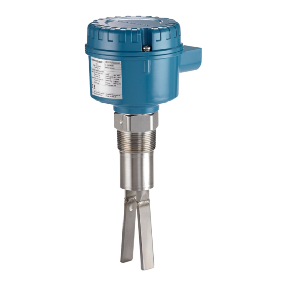
- Page 1 Quick Start Guide 00825-0100-2521, Rev AB October 2020 ™ Rosemount 2521 Solids Level Switch Vibrating Fork...
-
Page 2: Table Of Contents
Quick Start Guide October 2020 Contents Introduction..........................3 Mechanical installation.......................10 Electrical installation........................15 Configuration..........................24 Operation...........................29 Maintenance..........................33 Quick Start Guide... -
Page 3: Introduction
Equipment service needs. • 1-800-654-7768 (24 hours a day — includes Canada) • Outside of these areas, contact your local Emerson representative. WARNING Physical access Unauthorized personnel may potentially cause significant damage to and/or misconfiguration of end users’ equipment. This could be intentional or unintentional and needs to be protected against. - Page 4 Equipment ratings and certifications are no longer valid on any products that have been damaged or modified without the prior written permission of Emerson. Any continued use of product that has been damaged or modified without the written authorization is at the customer’s sole risk and expense.
- Page 5 Applications A Rosemount 2521 Solids Level Switch is used for monitoring the level of bulk materials in all types of containers and silos. The level switch can be used with all powdery and granulated bulk materials that do not show a strong tendency to form crusts or deposits.
- Page 6 787 in. (20 m) with an extension cable. The use of a sliding sleeve is recommended so that the switching point can be changed easily during the live operation of the level switch. Note The Rosemount 2521 Product Data Sheet has all dimensional drawings. Quick Start Guide...
- Page 7 Quick Start Guide Figure 1-1: Typical Installation Examples A. Rosemount 2521 with the cable-extended fork length B. Rosemount 2521 with the tube-extended fork length and thermal tube- extension C. Rosemount 2521 with the standard length fork D. Optional sliding sleeve...
- Page 8 Quick Start Guide October 2020 Figure 1-2: Detection of solids in water A. Rosemount 2521 with the tube-extended fork length and thermal tube- extension B. Rosemount 2521 with the standard length fork C. Optional sliding sleeve D. Solids in water...
- Page 9 'covered' state. The electrical output will vary depending on the electronics selected when the Rosemount 2521 was ordered. Quick Start Guide...
-
Page 10: Mechanical Installation
Ensure that the process connection is tightened by the correct amount of torque and sealed to prevent process leaks. 4. Technical data a. The Rosemount 2521 Product Data Sheet has all the technical specifications. See Emerson.com/Rosemount for other language versions. - Page 11 An installation example can be seen in Figure 1-2. 2.1.3 Mechanical load The load at the mounting point must not exceed 300 Nm (Rosemount 2521 with an extended length fork). Figure 2-1: Maximum Mechanical Load A. Mounting point B. Mechanical load 2.1.4...
- Page 12 A suitable gasket must be fitted to provide a seal when the flanges are tightened. 2.1.8 Tightening threaded process connections When tightening the threaded process connection of a Rosemount 2521: • Use an open-ended wrench on the hexagonal boss of the level switch or the sliding sleeve.
- Page 13 October 2020 Quick Start Guide 2.1.11 Rotatable housing and fork orientation mark The standard housing can be freely rotated to get the best position after being mounted to a process. On type 'D' and 'DE' housings, a fixing screw must first be loosened before the housing can be freely rotated. When the best position is achieved, re-tighten the fixing screw.
- Page 14 Quick Start Guide October 2020 Light bulk materials The signal output switches over when the forks of the level switch are covered a few centimeters. Mounting the level switch Figure 2-4 shows how the level switch should be mounted. Figure 2-4: Correct and Incorrect Mounting A.
-
Page 15: Electrical Installation
• Ensure the wiring is suitable for the electrical current and the insulation is suitable for the voltage, temperature, and environment. Wiring considerations Note See the Rosemount 2521 Product Data Sheet for the full electrical specifications. 3.2.1 Handling In cases of improper handling or handling malpractice, the electrical safety of the device cannot be guaranteed. - Page 16 Quick Start Guide October 2020 3.2.2 Installation regulations Local regulations or VDE 0100 (Regulations of German Electrotechnical Engineers) must be observed. When using 24 V supply voltage, an approved power supply with reinforced insulation to mains is required. 3.2.3 Fuse Use a fuse as stated in the connection diagrams.
- Page 17 The parts must be installed in accordance with the installation instructions of the part manufacturers. Installation of a flameproof or explosion-proof Rosemount 2521 with a conduit system In a conduit system, single electric conductors are installed in a certified pipe system.
- Page 18 Provide protection for relay contacts and output transistors to protect the device against inductive load surges. 3.2.9 Static charging The Rosemount 2521 must be grounded to avoid a static electrical build-up. This is particularly important for applications with pneumatic conveying and non-metallic containers. Wiring the level switch...
- Page 19 October 2020 Quick Start Guide Figure 3-2: Connections Overview for Type 'DE' Housings A. Connection terminals (in a terminal box for increased safety). The fixing torque is 0.5 - 0.6 Nm B. Protective conductor terminal - Protective Earth (PE) 3.3.1 Wiring the SPDT relay Power supply: •...
- Page 20 Quick Start Guide October 2020 3.3.2 Wiring the DPDT relay Power supply: • 19 to 230 Vac (50/60 Hz) +10%, 18 VA • 19 to 36 Vdc (for I.S. approvals) or to 55 Vdc +10%, 2 W Signal output (floating DPDT relay): •...
- Page 21 October 2020 Quick Start Guide 3.3.3 Wiring for 3-wire PNP Power supply: • 18 to 50 Vdc +10%, 1.5 W Signal output: • Maximum 0.4 A • Load in example from PLC, relay, bulb, etc. Fuse on power supply: maximum 4 A, slow or fast, HBC, 250 V Figure 3-5: 3-Wire PNP: Power Supply and Signal Output Connections Load Power supply...
- Page 22 • Load in example from PLC, relay, bulb, etc. Fuse on power supply: maximum 4 A, slow or fast, HBC, 250 V Note See the Rosemount 2521 Product Data Sheet for the full electrical specifications. Figure 3-6: 2-Wire: Power Supply and Load Connections...
- Page 23 October 2020 Quick Start Guide 3.3.5 Wiring for NAMUR (IEC 60947-5-6) Power supply: • 7 to 9 Vdc Signal output: • < 1 mA or > 2.2 mA switched output Figure 3-7: NAMUR Power Supply and Signal Output Connections Power supply Quick Start Guide...
-
Page 24: Configuration
Quick Start Guide October 2020 Configuration Configuring the signal output (FSH and FSL) Fail Safe High (FSH) and Fail Safe Low (FSL) configurations are supported on the following electronic modules: • SPDT relay • DPDT relay • 3-wire PNP • 2-wire without contact Figure 4-1 shows the SPDT relay electronics module as an example. - Page 25 October 2020 Quick Start Guide Configuring the signal output delay The two rotary switches (potentiometers) on the DPDT relay electronics are used for configuring delays of up to 30 seconds before the output signal changes. This feature can help prevent false switching of outputs caused by temporary movements of solids during filling or emptying operations.
- Page 26 PCB can be configured to indicate either state when there is a fault. Falling arrow fail-safe When the Rosemount 2521 is used to indicate a full-silo, set the PCB switch to the Falling Arrow fail-safe position. A power failure or line break is regarded as a full-silo signal (for protection against overfilling).
- Page 27 October 2020 Quick Start Guide Configuring the sensitivity The level switch is factory-set to high sensitivity (setting B) and normally does not need to be changed. However, if the bulk solids material has a frequent tendency to cake or deposit, a switch on the PCB can be changed to setting A to decrease the sensitivity of the fork sensor.
- Page 28 Quick Start Guide October 2020 Interface measurement option Versions of the Rosemount 2521 with a single rotary switch (potentiometer) on the electronics PCB can support interface measurements. Turn potentiometer towards Min: Vibrating fork gets less sensitive. Turn potentiometer towards Max: Vibrating fork gets more sensitive.
-
Page 29: Operation
October 2020 Quick Start Guide Operation Signal output switching logic (FSH or FSL) Figure 5-1: Switching Logic (All Versions Except NAMUR) 3 4 5 3 4 5 3 4 5 3 4 5 3 4 5 7 8 9 3 4 5 7 8 9 3 4 5 7 8 9... - Page 30 Quick Start Guide October 2020 Signal output from NAMUR (switching logic) Figure 5-2: Switching Logic (NAMUR Only) I < 1 mA I > 2.2 mA I > 2.2 mA I < 1 mA A. Setting: Rising or Falling fail-safe B. NAMUR electronics (IEC 60947-5-6) C.
- Page 31 A. LED Test button for diagnostics Versions of the Rosemount 2521 with NAMUR electronics can be tested for vibration anomalies and electronic malfunctions while installed in a silo or other storage vessel. A test button is on the electronic PCB (see Figure 5-4).
- Page 32 When the fork is covered with solids material, the test button has no effect. LED for diagnostics Versions of the Rosemount 2521 with NAMUR electronics have a LED for indicating diagnostics while installed in a silo or other storage vessel. The...
-
Page 33: Maintenance
October 2020 Quick Start Guide Maintenance Opening the lid (cover) Before opening the lid for maintenance reasons, consider the following: • Check the certifications on the product label and then review Table 6-1. • Review the section Safety. • Ensure that no dust deposits or airborne dusts are present. •... - Page 34 Production date The production year is shown on the nameplate. Spare parts Refer to the Rosemount 2521 Product Data Sheet for all spare parts. Quick Start Guide...
- Page 35 October 2020 Quick Start Guide Quick Start Guide...
- Page 36 The Emerson logo is a Twitter.com/Rosemount_News trademark and service mark of Emerson Electric Facebook.com/Rosemount Co. Rosemount is a mark of one of the Emerson Youtube.com/user/ family of companies. All other marks are the RosemountMeasurement property of their respective owners.