Table of Contents
Quick Links
Table of Contents

Related Manuals for ABB ACX580-01 R1


Summary of Contents for ABB ACX580-01 R1
- Page 1 ABB drives Supplement ACX580-01 R1-R3 Flange mounting kit installation...
- Page 2 Internet on the inside of the back cover. For manuals not available in the Document library, contact your local ABB representative. The code below opens an on-line listing of the manuals applicable to the product. ACS580-01 manuals...
- Page 3 Supplement Flange mounting kit installation Table of contents 3. Mechanical installation 2017 ABB Oy. All Rights Reserved. 3AXD50000119189 Rev A EFFECTIVE: 2017-10-10...
-
Page 5: Table Of Contents
Table of contents 5 Table of contents List of related manuals ............2 1. - Page 6 Providing feedback on ABB Drives manuals ........
-
Page 7: Introduction To The Supplement
Introduction to the supplement 7 Introduction to the supplement Contents of this chapter This chapter describes the supplement. Applicability This supplement applies to the flange mounting kits of the ACS580-01, ACH580-01 and ACQ580-01 drives (frames R1 to R3). Safety instructions Obey the general safety instructions in the hardware manual and the task-specific instructions in this supplement. -
Page 8: Contents Of The Manual
8 Introduction to the supplement Contents of the manual The chapters of the supplement are briefly described below. Introduction to the supplement introduces the supplement. Hardware description describes the flange mounting kit. Mechanical installation describes how to install the drive with the flange mounting kit mechanically. -
Page 9: Hardware Description
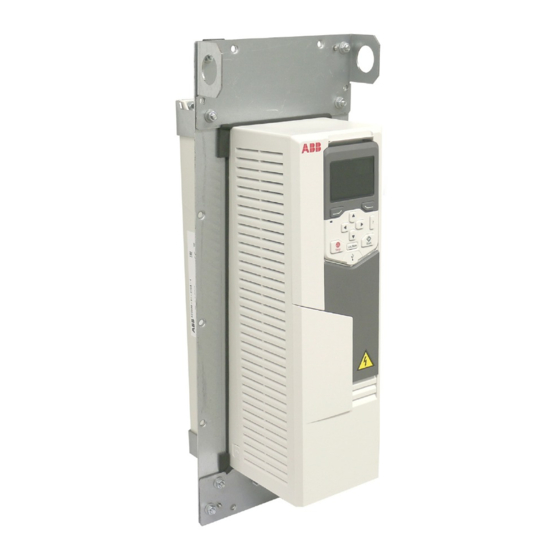
Hardware description 9 Hardware description Contents of this chapter This chapter describes the flange mounting kit. Product overview The flange mounting kit contains brackets for attaching the drive onto a mounting plate so that the heat sink of the drive is in the cooling air channel and the front part on the other side of the mounting plate. - Page 10 10 Hardware description With some frame sizes, you must insert a sealing plug into the drive. Also with some degrees of protection, you must leave the drive cover in place. See the tables for more information. Frame size ACX580-01 IP21 ACX580-01 IP55 Delivered with cover.
-
Page 11: Layout
Hardware description 11 Layout Mounting plate Top flange bracket Lifting hole Side flange bracket Cable shelf Bottom flange bracket Grouding plate Drive heat sink in the cooling air channel Note: If flanges are mounted, cable boxes are removed from R1 and R2 drive modules. - Page 12 12 Hardware description...
-
Page 13: Mechanical Installation
Mechanical installation 13 Mechanical installation Contents of this chapter This chapter describes how to install the drive with the flange mounting kit mechanically. -
Page 14: Examining The Installation Site
14 Mechanical installation Examining the installation site Make sure that the installation site agrees with these requirements: • The installation site has sufficient ventilation to prevent overheating of the drive. See section Losses, cooling data and noise in the hardware manual for the required air flow in the cooling air channel and in the front part of the drive. -
Page 15: Unpacking And Examining The Delivery
Mechanical installation 15 Unpacking and examining the delivery Transport package contents The flange mounting kit package is either in the drive package, tied with straps onto the drive package or sent separately. Examine that all items are present and there are no signs of damage. -
Page 16: Flange Mounting Kit Package Contents
16 Mechanical installation Flange mounting kit package contents The illustrations show the layout of the flange mounting kit packages. Examine that all items are present and there are no signs of damage. ACX580-01 frames R1 to R3 Mounting template Quick guide Grounding plate for R3 Tightening brackets... -
Page 17: Example Mounting Template
Mechanical installation 17 Example mounting template The flange mounting kit package includes a template in actual size for drilling the attaching holes and cutting the holes in the mounting plate. For drilling the holes, see the installation procedures for: •... -
Page 18: Installing The Drive
18 Mechanical installation Installing the drive Free space requirements The flange-mounted drives can be installed side by side. For free space requirements above and below the drives, see the table. ACX580-01 Above Below 200 7.87 200 7.87 Above 200 7.87 200 7.87 200 7.87 200 7.87... -
Page 19: Installing Drives Above One Another
Mechanical installation 19 Installing drives above one another Make sure that the outlet cooling air flows away from the drive above. 200 mm (7.87 in.) 120 mm (4.72 in.) 250 mm (9.84 in.) 120 mm (4.72 in.) 300 mm (11.81 in.) -
Page 20: Installation Procedure
20 Mechanical installation Installation procedure ACX580-01 frames R1 to R3 1. Frames R1 and R2: To remove the cable box, front cover is removed firstly. Reinstall the cover and screws. 2. Frames R1 to R3: To remove the fan assembly, push the retaining clips. Lift the assembly up. - Page 21 Mechanical installation 21 3. Frames R3: Insert the sealing plug to the hole shown in the figure.Note: For IP55/ UL Type 12 unit only. 4. Frames R1 to R3: Reinstall the fan assembly.
- Page 22 22 Mechanical installation 5. Frames R1 to R3: Attach the top and bottom U-brackets to the drive. 4 × M6 nut 6 N·m 6. Frames R1 to R3: First attach the side brackets (a) to the top and bottom U- brackets with M6 nuts.
- Page 23 Mechanical installation 23 7. Frames R1 to R3: Attach the top (c) and bottom (d) brackets to the side brackets, first the inner sides of the top and bottom brackets (the sides that touch the drive), then the outer sides. Remove the tightening bracket (e) from the front of the fan. 8 ×...
-
Page 24: Optional Steps
24 Mechanical installation 8. Grounding • For safe reason,make protective earthing for the flange. Frames R1...R2: 2 × M4 nut 1.5 N·m 2 × M4 × 8 Combi screw 1.5 N·m Frame R3: 2 × M4 nut 1.5 N·m Note: Use the uninstalled screw from drive for grouding Optional steps: •... - Page 25 Mechanical installation 25 Note: Frame R3 is shown here as an example. The cable shelf varies in different frame sizes. Note: Reinstall the screws to avoid moisture exchange through the empty holes! 1.5 N·m 2 × M4 nut 1.5 N·m...
- Page 26 26 Mechanical installation 9. See chapter Dimension drawings for the dimensions of the flange and the required opening in the mounting plate. Attach the mounting template from the flange mounting kit package onto the mounting plate. Note: Mounting templates are different (size, number and position of holes) for different frame sizes.
- Page 27 Mechanical installation 27 10. UL Type 12 drives: Attach the hood to the cooling channel. Note: UL Type 12 is fulfilled on the drive backside when the flange and hood are installed. Step 10 is not required for IP55. R1…R2: 2 ×...
- Page 28 28 Mechanical installation 11. Attach chains to the drive lifting holes and lift the drive with a lifting device onto the opening in the mounting plate. 12. Attach the bottom bracket with one screw. 13. Attach the top bracket with one screw. 14.
-
Page 29: Dimension Drawings
Dimension drawings 29 Dimension drawings Contents of this chapter This chapter contains the dimension drawings of the flange mounting kits and required openings in the mounting plate. -
Page 30: Acx580-01 Frame R1
30 Dimension drawings ACX580-01 frame R1 Flange mounting kit... - Page 31 Dimension drawings 31 Hood is needed for UL Type 12 drives...
-
Page 32: Attaching Points And Hole Dimensions
32 Dimension drawings Attaching points and hole dimensions 3AXD50000038098... -
Page 33: Acx580-01 Frame R2
Dimension drawings 33 ACX580-01 frame R2 Flange mounting kit... - Page 34 34 Dimension drawings Hood is needed for UL Type 12 drives...
-
Page 35: Attaching Points And Hole Dimensions
Dimension drawings 35 Attaching points and hole dimensions 3AXD50000038111... -
Page 36: Acx580-01 Frame R3
36 Dimension drawings ACX580-01 frame R3 Flange mounting kit... - Page 37 Dimension drawings 37 Hood is needed for UL Type 12 drives...
-
Page 38: Attaching Points And Hole Dimensions
38 Dimension drawings Attaching points and hole dimensions 3AXD50000038117... -
Page 39: Further Information
Product and service inquiries Address any inquiries about the product to your local ABB representative, quoting the type designation and serial number of the unit in question. A listing of ABB sales, support and service contacts can be found by navigating to www.abb.com/searchchannels. - Page 40 Contact us www.abb.com/drives www.abb.com/drivespartners 3AXD50000119189 RevA (EN) 2017-10-10...