Table of Contents
Quick Links
Table of Contents

Related Manuals for ABB 3AXD50000018852


Summary of Contents for ABB 3AXD50000018852
- Page 1 ABB industrial drives Supplement Flange mounting kit installation...
- Page 2 Document library on the Internet on the inside of the back cover. For manuals not available in the Document library, contact your local ABB representative. The QR code below opens an on-line listing of the manuals applicable to the product.
- Page 3 Supplement Flange mounting kit installation Table of contents 3. Mechanical installation 2015 ABB Oy. All Rights Reserved. 3AXD50000019100 Rev A EFFECTIVE: 2015-01-20...
-
Page 5: Table Of Contents
Providing feedback on ABB Drives manuals ........ - Page 6 6 Table of contents...
-
Page 7: Introduction To The Supplement
Introduction to the supplement 7 Introduction to the supplement Contents of this chapter This chapter describes the supplement. Applicability This supplement applies to ACS880-01 drive flange mounting kit (option +C135) and to ACS580-01 and ACH580-01 drive flange mounting kits. Safety instructions Obey the general safety instructions in the hardware manual and the task specific instructions in this supplement. -
Page 8: Contents Of The Manual
8 Introduction to the supplement Contents of the manual The chapters of the supplement are briefly described below. Introduction to the supplement introduces the supplement. Hardware description describes the flange mounting kit. Mechanical installation describes how to install the drive with the flange mounting kit mechanically. -
Page 9: Hardware Description
The flange mounting kit is a plus code option (+C135) or can be ordered with these ordering codes also as retrofit. Frame size Ordering code 3AXD50000018852 3AXD50000018853 3AXD50000018854 3AXD50000018855 The kit parts can be attached to the drive module with no front cover (option +P940) or to the drive with front cover but without the cable entry box. -
Page 10: Layout
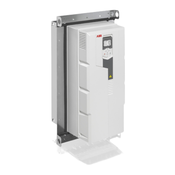
10 Hardware description Layout Hood (for UL type 12) Top flange bracket Mounting plate Lifting hole Drive heat sink in the cooling air channel Side flange bracket Drive front side Bottom flange bracket Flange mounted – Drive with front cover Flange mounted –... -
Page 11: Mechanical Installation
Mechanical installation 11 Mechanical installation Contents of this chapter This chapter describes how to install the drive with the flange mounting kit mechanically. Safety WARNING! For frame sizes R6 to R9: Use the lifting eyes of the drive when you lift the drive. Do not tilt the drive. The drive is heavy and its center of gravity is high. -
Page 12: Examining The Installation Site
12 Mechanical installation Examining the installation site Make sure that the installation site agrees with these requirements: • The installation site has sufficient ventilation to prevent overheating of the drive. See section Losses, cooling data and noise in the hardware manual for the required air flow in the cooling air channel and in the front part of the drive. -
Page 13: Unpacking And Examining The Delivery (Frames R6 To R9)
Mechanical installation 13 Unpacking and examining the delivery (frames R6 to R9) Transport package contents This illustration shows the layout of the drive module package with option +C135. In other deliveries, the kit package is tied with straps onto the drive package or sent separately. -
Page 14: Flange Mounting Kit Package Contents
14 Mechanical installation Flange mounting kit package contents Screw package: • M6 nut (15 pcs) • M6×10 T30 (12 pcs) • M6×25 T25 (18 pcs) • K40×12 (3 pcs used for frames R4 and R5 only) Mounting template Quick guide Option kit package label Side bracket Top bracket... -
Page 15: Installing The Drive
Mechanical installation 15 Installing the drive Free space requirements The flange-mounted drives can be installed side by side. 200 mm (7.87 in.) free space is required at the top of the drive and 300 mm (11.81 in.) at the bottom of the drive. -
Page 16: Installing Drives Above One Another
16 Mechanical installation Installing drives above one another Make sure that the outlet cooling air flows away from the drive above. 200 mm (7.87 in.) 200 mm (7.87 in.) 500 mm (19.68 in.) 200 mm (7.87 in.) 200 mm (7.87 in.) -
Page 17: Installation Procedure
Mechanical installation 17 Installation procedure 1. Attach the side brackets of the flange to the drive. 12 × M6×12 T30 6 N·m 2. Attach the top and bottom brackets. 8 × M6 nut 6 N·m... - Page 18 18 Mechanical installation 3. See chapter Dimension drawings for the dimensions of the flange and the required opening in the mounting plate. Attach the mounting template from the flange mounting kit package onto the mounting plate. Make the opening and drill the holes for the mounting screws.
- Page 19 Mechanical installation 19 4. For UL Type 12 drives, attach hood. 3 × M6 nut 6 N·m Bottom Back 5. Attach chains to the drive lifting holes and lift the drive with a lifting device onto the opening in the mounting plate.
- Page 20 20 Mechanical installation 6. Attach the top bracket with one screw. 1 × M6×25 6 N·m 7. Attach the bottom bracket with one screw. 1 × M6×25 6 N·m...
- Page 21 Mechanical installation 21 8. Attach the rest of the mounting screws. Remove the chains. 14 × M6×25 6 N·m...
- Page 22 22 Mechanical installation...
-
Page 23: Dimension Drawings
Dimension drawings 23 Dimension drawings Contents of this chapter This chapter contains the dimension drawings of the flange mounting kits and required openings in the mounting plate. -
Page 24: Flange Mounting Kit For Frame R6
24 Dimension drawings Flange mounting kit for frame R6... - Page 25 Dimension drawings 25 Hood is needed for UL Type 12 drives...
- Page 26 26 Dimension drawings Attaching points and hole dimensions for frame R6...
- Page 27 Dimension drawings 27 Flange mounting kit for frame R7...
- Page 28 28 Dimension drawings Hood is needed for UL Type 12 drives...
- Page 29 Dimension drawings 29 Attaching points and hole dimensions for frame R7...
- Page 30 30 Dimension drawings Flange mounting kit for frame R8...
- Page 31 Dimension drawings 31 Hood is needed for UL Type 12 drives...
- Page 32 32 Dimension drawings Attaching points and hole dimensions for frame R8...
- Page 33 Dimension drawings 33 Flange mounting kit for frame R9...
- Page 34 34 Dimension drawings Hood is needed for UL Type 12 drives...
- Page 35 Dimension drawings 35 Attaching points and hole dimensions for frame R9...
- Page 36 36 Dimension drawings...
-
Page 37: Further Information
Product and service inquiries Address any inquiries about the product to your local ABB representative, quoting the type designation and serial number of the unit in question. A listing of ABB sales, support and service contacts can be found by navigating to www.abb.com/searchchannels. - Page 38 Contact us www.abb.com/drives www.abb.com/drivespartners 3AXD50000019099 Rev A (EN) 2015-01-20...