YASKAWA DX100 Operator's Manual
For material handling, press tending, cutting, and other applications
Hide thumbs
Also See for DX100:
- Maintenance manual (729 pages) ,
- Operator's manual (520 pages) ,
- Instructions manual (328 pages)
Table of Contents
Quick Links
DX100
OPERATOR'S MANUAL
FOR MATERIAL HANDLING, PRESS TENDING, CUTTING,
AND OTHER APPLICATIONS
Upon receipt of the product and prior to initial operation, read these instructions thoroughly, and retain
for future reference.
MOTOMAN INSTRUCTIONS
MOTOMAN- INSTRUCTIONS
DX100 INSTRUCTIONS
DX100 OPERATOR'S MANUAL
DX100 MAINTENANCE MANUAL
The DX100 operator's manuals above correspond to specific usage.
Be sure to use the appropriate manual.
Part Number:
155507-1CD
Revision:
7
MANUAL NO.
RE-CSO-A037
1 of 554
7
Table of Contents

Related Manuals for YASKAWA DX100


Summary of Contents for YASKAWA DX100
- Page 1 MOTOMAN INSTRUCTIONS MOTOMAN- INSTRUCTIONS DX100 INSTRUCTIONS DX100 OPERATOR’S MANUAL DX100 MAINTENANCE MANUAL The DX100 operator’s manuals above correspond to specific usage. Be sure to use the appropriate manual. Part Number: 155507-1CD Revision: MANUAL NO. 1 of 554...
- Page 2 Copyright © 2018, 2015, 2013, 2012 Yaskawa America, Inc. Terms of Use and Copyright Notice All rights reserved. This manual is freely available as a service to Yaskawa customers to assist in the operation of Motoman robots, related equipment and software This manual is copyrighted property of Yaskawa and may not be sold or redistributed in any way.
- Page 3 If such modification is made, the manual number will also be revised. • If your copy of the manual is damaged or lost, contact a YASKAWA representative to order a new copy. The representatives are listed on the back cover. Be sure to tell the representative the manual number listed on the front cover.
- Page 4 ALLOW UNTRAINED PERSONNEL TO OPERATE, PROGRAM, OR REPAIR THE EQUIPMENT! We recommend approved Yaskawa training courses for all personnel involved with the operation, programming, or repair of the equipment. This equipment has been tested and found to comply with the limits for a Class A digital device, pursuant to part 15 of the FCC rules.
- Page 5 Notes for Safe Operation Notes for Safe Operation Read this manual carefully before installation, operation, maintenance, or inspection of the DX100. In this manual, the Notes for Safe Operation are classified as “DANGER”, “WARNING,” “CAUTION,” “MANDATORY,” or “PROHIBITED.” Indicates an imminent hazardous...
- Page 6 Confirm that no person is present in the P-point maximum envelope of the manipulator and that you are in a safe location before: – Turning on the power for the DX100. – Moving the manipulator with the programming pendant. – Running the system in the check mode.
- Page 7 Read and understand the Explanation of Warning Labels in the DX100 Instructions before operating the manipulator. Definition of Terms Used In this Manual The MOTOMAN is the YASKAWA industrial robot product. The MOTOMAN usually consists of the manipulator, the controller, the programming pendant, and supply cables.
- Page 8 155507-1CD DX100 Description of the Operation Procedure Descriptions of the programming pendant keys, buttons, and displays are shown as follows: Equipment Manual Designation Programming Character Keys The keys which have characters printed on Pendant them are denoted with [ ].
- Page 9 155507-1CD DX100 Safeguarding Tips Safeguarding Tips All operators, programmers, maintenance personnel, supervisors, and anyone working near the system must become familiar with the operation of this equipment. All personnel involved with the operation of the equipment must understand potential dangers of operation. General safeguarding tips are as follows: •...
- Page 10 Do not make any modifications to the controller unit. Making any changes without the written permission from Yaskawa will void the warranty. • Some operations require standard passwords and some require special passwords.
- Page 11 Turn the power OFF and disconnect and lockout/tagout all electrical circuits before making any modifications or connections. Perform only the maintenance described in this manual. Maintenance other than specified in this manual should be performed only by Yaskawa- trained, qualified personnel. Summary of Warning Information This manual is provided to help users establish safe conditions for operating the equipment.
- Page 12 155507-1CD DX100 Customer Support Information Customer Support Information If you need assistance with any aspect of your DX100 system, please contact YASKAWA Customer Support at the following 24-hour telephone number: (937) 847-3200 For routine technical inquiries, you can also contact YASKAWA Customer Support at the following e-mail address: [email protected]...
-
Page 13: Table Of Contents
155507-1CD DX100 Table of Contents Table of Contents 1 Introduction ............................. 1-1 1.1 DX100 Overview........................ 1-1 1.2 Programming Pendant....................... 1-2 1.2.1 Programming Pendant Overview................1-2 1.2.2 Key Description ....................1-3 1.2.2.1 Character Keys ..................1-3 1.2.2.2 Symbol Keys ................... 1-3 1.2.2.3 Axis Keys and Numeric Keys .............. - Page 14 155507-1CD DX100 Table of Contents 2.2 General Operations......................2-3 2.2.0.1 Check Safety ................... 2-3 2.2.0.2 Select Teach Mode ................. 2-3 2.2.0.3 Select Control Group ................2-3 2.2.0.4 Select Coordinate System ............... 2-3 2.2.0.5 Select Manual Speed ................2-4 2.2.0.6 Servo ON....................2-4 2.2.0.7 Axis Operation ..................
- Page 15 155507-1CD DX100 Table of Contents 3.2.3 Teaching Steps ....................3-11 3.2.3.1 Registering Move Instructions ............... 3-11 3.2.3.2 Registering Reference Point Instructions ..........3-18 3.2.3.3 Registering Timer Instructions............... 3-19 3.2.4 Overlapping the First and Last Steps ..............3-22 3.3 Checking Steps........................ 3-23 3.3.1 FWD/BWD Key Operations ................
- Page 16 155507-1CD DX100 Table of Contents 3.6 Editing Instructions......................3-50 3.6.1 Instruction Group ....................3-51 3.6.2 Inserting Instructions................... 3-52 3.6.3 Deleting Instructions ................... 3-55 3.6.4 Modifying Instructions ..................3-55 3.6.5 Modifying Additional Numeric Data..............3-59 3.6.6 Modifying Additional Items.................. 3-60 3.6.7 Inserting Additional Items ................... 3-61 3.6.8 Deleting Additional Items ..................
- Page 17 155507-1CD DX100 Table of Contents 3.9.8 Front/Back ......................3-91 3.9.9 Upper Arm/Lower Arm..................3-93 3.9.10 S-axis Angle ..................... 3-93 3.9.11 Editing Local Variables ..................3-94 3.9.11.1 Setting the Number of Local Variables..........3-96 3.9.12 Search ......................3-98 3.9.12.1 Line Search ..................3-99 3.9.12.2 Step Search ..................
- Page 18 155507-1CD DX100 Table of Contents 4.3.4 Others .........................4-19 4.3.4.1 Temporary Stop by Mode Change ............4-19 4.3.4.2 Temporary Stop by the PAUSE Instruction ........... 4-19 4.4 Modifying Play Speed ...................... 4-20 4.4.1 Speed Override....................4-20 4.4.1.1 Setting Speed Overrides ............... 4-21 4.4.1.2 Modifying Play Speed................
- Page 19 155507-1CD DX100 Table of Contents 6 Convenient Functions ........................6-1 6.1 One-touch Operation “Direct Open”................... 6-1 6.2 Job Edit Function During Playback..................6-3 6.2.1 Function........................ 6-3 6.2.2 Job Edit During Playback ..................6-3 6.2.2.1 Basic Operation..................6-3 6.2.2.2 Editing ..................... 6-6 6.2.2.3 Editing Multiple Jobs ................
- Page 20 155507-1CD DX100 Table of Contents 6.5 PAM Function ........................6-47 6.5.1 Function Overview ....................6-47 6.5.1.1 Input Ranges for Adjustment Data ............6-47 6.5.2 Operating Methods ..................... 6-49 6.5.2.1 Setting Adjustment Data................ 6-49 6.5.2.2 Executing the Adjustment..............6-51 6.6 Mirror Shift Function......................6-55 6.6.1 Function Overview ....................
- Page 21 155507-1CD DX100 Table of Contents 6.7.5 Switching the Axis Operation Control Group ............6-74 6.7.5.1 S2C540 “Choosing Method of Notifying the Change of Axis Operation Control Group when Switching the Active Window” ..... 6-74 6.8 Simple Menu Function ....................6-76 6.8.1 Simple Menu ......................
- Page 22 155507-1CD DX100 Table of Contents 6.11 Energy-Saving Function....................6-115 6.11.1 Energy-Saving Function ................. 6-115 6.11.2 Energy-Saving Setting Method ............... 6-116 6.11.2.1 Valid/Invalid of Energy-Saving Setting ..........6-116 6.11.2.2 Accumulated Energy-Saving Time Clearance........6-118 6.11.3 Energy-Saving Status Confirmation Method........... 6-120 6.11.3.1 Confirmation by the accumulated energy-saving time....... 6-120 6.11.3.2 Confirmation by System Signal Output..........
- Page 23 155507-1CD DX100 Table of Contents 7 External Memory Devices ....................... 7-1 7.1 Memory Devices ........................ 7-1 7.1.1 Compact Flash (CF Cards)................... 7-2 7.1.1.1 Recommended Compact Flash Cards ............ 7-2 7.1.1.2 Notes on handling Compact Flash ............7-2 7.1.1.3 Inserting a Compact Flash ..............7-3 7.1.2 USB Memory Stick ....................
- Page 24 155507-1CD DX100 Table of Contents 8.2.0.16 S2C422: OPERATION AFTER RESET FROM PATH DEVIATION ..8-7 8.2.0.17 S2C423: OPERATION AFTER JOB............8-7 8.2.0.18 S2C424: DEVIATED POSITION ............8-8 8.2.0.19 S2C425: CIRCULAR INTERPOLATION TOOL POSITION CONTROL 8-9 8.2.0.20 S2C653: EMERGENCY STOP CURSOR ADVANCE ...
- Page 25 155507-1CD DX100 Table of Contents 8.3.0.30 S2C293: REMOTE FIRST CYCLE MODE.......... 8-20 8.3.0.31 S2C294: LOCAL FIRST CYCLE MODE ..........8-20 8.3.0.32 S2C312: POWER ON FIRST CYCLE MODE ........8-20 8.3.0.33 S2C313: TEACH MODE FIRST CYCLE MODE ......... 8-21 8.3.0.34 S2C314: PLAY MODE FIRST CYCLE MODE ........8-21 8.3.0.35 S2C316: START CONDITION AFTER ALARM-4107 ...
- Page 26 155507-1CD DX100 Table of Contents 8.6.0.3 S2C231: OPERATION METHOD AT FWD/BWD OPERATION OR TEST RUN BY INDEPENDENT CONTROL ........8-45 8.6.0.4 S2C232: JOB AT CALLING MASTER OF SUBTASK BY INDEPENDENT CONTROL ............8-46 8.6.0.5 S2C264: STATION AXIS CURRENT VALUE DISPLAY FUNCTION..8-46 8.6.0.6 S2C265 to S2C288: STATION AXIS DISPLAYED UNIT ......
- Page 27 155507-1CD DX100 Table of Contents 8.10.1.6 AxP010: WELDING INSTRUCTION OUTPUT........8-56 8.10.1.7 AxP011, AxP012: MANUAL WIRE OPERATION SPEED ....8-56 8.10.1.8 AxP013, AxP014: WELDING CONTROL TIME ........8-56 8.10.1.9 AxP015 to AxP017: NUMBER OF WELDING CONTROL ....8-56 8.10.1.10 AxP026 to AxP029: TOOL ON/OFF USER OUTPUT NO. ...
- Page 28 155507-1CD DX100 Table of Contents 9.3 Using Files ........................9-30 9.3.1 Weaving Basic Coordinate System ..............9-30 9.3.2 WEAVING CONDITION Window................ 9-31 9.3.3 Operation Method ....................9-34 9.3.3.1 Displaying a Weaving File ..............9-34 9.3.3.2 Editing Condition Data................9-34 9.3.3.3 Cases that Require the Registration of Reference Points ..... 9-34 9.3.3.4 Prohibiting Weaving................
-
Page 29: Introduction
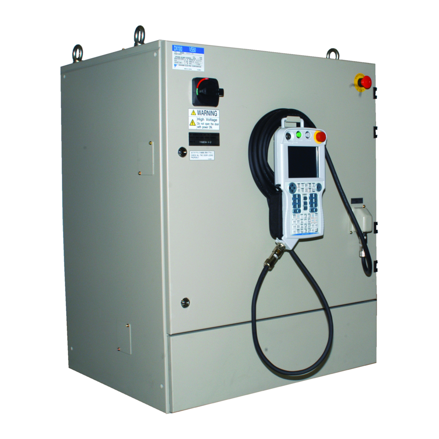
DX100 Overview The main power switch and the door lock are located on the front of the DX100 controller. The emergency stop button is installed in the upper right corner of the cabinet door and the programming pendant hangs from a hook below the button. -
Page 30: Programming Pendant
155507-1CD DX100 Introduction 1.2 Programming Pendant Programming Pendant 1.2.1 Programming Pendant Overview The programming pendant is equipped with the keys and buttons used to conduct manipulator teaching operations and to edit jobs. Fig. 1-2: PP Overview Start button Hold button... -
Page 31: Key Description
155507-1CD DX100 Introduction 1.2 Programming Pendant 1.2.2 Key Description 1.2.2.1 Character Keys The keys which have characters printed on them are denoted with [ ]. For example, is shown as [ENTER]. ENTER The Numeric keys have additional functions along with their number values. -
Page 32: Programming Pendant Keys
155507-1CD DX100 Introduction 1.2 Programming Pendant 1.2.3 Programming Pendant Keys [START] Starts the manipulator motion in playback operation. • The lamp on this button is lit during the play operation. The lamp also lights when the playback operation is started by the system input START signal. - Page 33 155507-1CD DX100 Introduction 1.2 Programming Pendant Enable Switch Turns ON the servo power. When the Enable switch is lightly squeezed while the SERVO ON LED is blinking and the Mode Switch is set to “TEACH”, the power is turned ON.
- Page 34 155507-1CD DX100 Introduction 1.2 Programming Pendant [SERVO ON READY] Enables the servo power supply to be turned ON. Press this button to enable the servo power supply to be turned ON if the servo power supply is shut OFF by the emergency stop or overrun signal.
- Page 35 155507-1CD DX100 Introduction 1.2 Programming Pendant [DIRECT OPEN] Displays the content related to the current line. • To display the content of a CALL job or condition file, move the cursor to the next line and press DIRECT DIRECT OPEN OPEN [DIRECT OPEN].
- Page 36 LIST [ROBOT] Enables the robot axis operation. [ROBOT] is active for the system where multiple manipulators are controlled by one DX100 or the ROBOT system with external axes. [SHIFT] + [ROBOT] The robot under axis operation can be switched to a robot axis which is not registered to the currently selected job.
- Page 37 155507-1CD DX100 Introduction 1.2 Programming Pendant [TEST START] Moves the manipulator through taught steps in a continuous motion when [TEST START] and [INTERLOCK] are simultaneously pressed. The manipulator can be moved to check the path of TEST taught steps. Operation stops immediately when this START key is released.
- Page 38 155507-1CD DX100 Introduction 1.2 Programming Pendant [ENTER] Registers instructions, data, current position of the manipulator, etc. • When [ENTER] is pressed, the instruction or data displayed in the input buffer line moves to ENTER the cursor position to complete a registration, insertion, or modification.
-
Page 39: Programming Pendant Display
155507-1CD DX100 Introduction 1.2 Programming Pendant 1.2.4 Programming Pendant Display The programming pendant display is a 5.7 inch color display. Alphanumeric characters can be used. 1.2.4.1 Five Display Areas The general-purpose display area, menu area, human interface display area, and main menu area among the following five areas can be moved by pressing [AREA], or can be selected by directly touching the screen. -
Page 40: General-Purpose Display Area
155507-1CD DX100 Introduction 1.2 Programming Pendant 1.2.4.2 General-purpose Display Area On the general-purpose display area, various settings and contents such as jobs and characteristics files can be displayed and edited. The operation buttons are also displayed at the bottom of the window according to the window contents. -
Page 41: Main Menu Area
155507-1CD DX100 Introduction 1.2 Programming Pendant 1.2.4.3 Main Menu Area Each menu and submenu are displayed in the main menu area. Press [MAIN MENU] or touch {Main Menu} on the left bottom of the window to display the main menu. - Page 42 155507-1CD DX100 Introduction 1.2 Programming Pendant B. Operation Coordinate System Displays the selected coordinate system. Switched by pressing [COORD]. : Joint Coordinates : Cartesian Coordinates : Cylindrical Coordinates : Tool Coordinates : User Coordinates C. Manual Speed Displays the selected speed. For details, refer to section 2.2.0.5 “Select Manual Speed”...
- Page 43 155507-1CD DX100 Introduction 1.2 Programming Pendant F. State Under Execution Displays the present system status (STOP, HOLD, ESTOP, ALARM, or RUN). : Stop Status : Hold Status : Emergency Stop Status : Alarm Status : Operating Status G. Mode : Teach mode : Play mode H.
-
Page 44: Human Interface Display Area
155507-1CD DX100 Introduction 1.2 Programming Pendant 1.2.4.5 Human Interface Display Area An error(s) or a message(s) is displayed in the human interface display area. Turn on servo power When an error is displayed, operations cannot be performed until the error is canceled. -
Page 45: Screen Descriptions
155507-1CD DX100 Introduction 1.2 Programming Pendant 1.2.5 Screen Descriptions • The menu displayed in the programming pendant is denoted with { }. The above menu items are denoted with {DATA}, {EDIT}, {DISPLAY}, AND {UTILITY}. • The window can be displayed according to the view desired. -
Page 46: Character Input Operation
155507-1CD DX100 Introduction 1.2 Programming Pendant 1.2.6 Character Input Operation Move the cursor to the data for which characters are to be input, and press [SELECT] to display the software keypad. 1.2.6.1 Character Input To input characters, the software keypad is shown on the programming pendant display. -
Page 47: Alphanumeric Input
155507-1CD DX100 Introduction 1.2 Programming Pendant 1.2.6.3 Alphanumeric Input Number input is performed with the Numeric keys or on the following alphanumeric input window. Numbers include 0 to 9, the decimal point (.), and the minus sign/hyphen (-). Note however, that the decimal point cannot be used in job names. -
Page 48: Symbol Input
155507-1CD DX100 Introduction 1.2 Programming Pendant 1.2.6.4 Symbol Input GO BACK GO BACK Press the page key to display the symbol input window. PAGE PAGE Move the cursor to the desired symbol and press [SELECT] to enter the symbol. Note that only some symbols are available for naming jobs. -
Page 49: Register Word Function
155507-1CD DX100 Introduction 1.2 Programming Pendant 1.2.6.5 Register Word Function This function enables to use the registered word when input a character by registering the word (character string) in advance. To use this function simplifies to input the same character strings. ... - Page 50 155507-1CD DX100 Introduction 1.2 Programming Pendant Word Registration It is able to register the 32 words of eight characters. Register a word by selecting [REGISTER WORD] button while the word editing is valid (S2C410=1) during using the keyboard, or register the word in the word register screen.
- Page 51 155507-1CD DX100 Introduction 1.2 Programming Pendant Select [REGISTER WORD]. – The word area appears. – Confirm that [TEST] is in the word area. Back Space Delete the last character of the input character string. Select [Back space] in the word register screen.
- Page 52 155507-1CD DX100 Introduction 1.2 Programming Pendant Use of Words e.g. Use the registered word [TEST]. Select [REGISTER WORD]. – The word area is displayed. There is a limit to enter the character by input contents. If a registered word includes a limited character, it is unable to use the word.
- Page 53 155507-1CD DX100 Introduction 1.2 Programming Pendant Select [KEYBORD]. Move the focus to “1” by the programming pendant, and press [Select]. – The “1” is added after [TEST] in the [Result]. While [TEST1] is displayed in the [Result], select [Regist]. The dial box, which says {“TEST1” Word registration succeeded. } appears, and the registration is completed.
- Page 54 155507-1CD DX100 Introduction 1.2 Programming Pendant Change the Arrangement of the Words to Display Able to change the arrangement of the words to display. 1. Name order display Select [Name order] in the button area. – Displayed by the name order of the words.
- Page 55 155507-1CD DX100 Introduction 1.2 Programming Pendant Delete the Word Able to delete the registered words. Delete the words while the word editing is valid (S2C410=1) during using the keyboard, or delete the word in the word register screen. e.g. Delete registered word “TEST”. ...
- Page 56 155507-1CD DX100 Introduction 1.2 Programming Pendant Delete All Words Able to delete all registered words. Delete while the word editing is valid (S2C410=1) during using the keyboard, or delete the word in the word register screen. • Delete all registered words. ...
-
Page 57: Mode
155507-1CD DX100 Introduction 1.3 Mode Mode The following three modes are available for DX100. • Teach Mode • Play Mode • Remote Mode 1.3.1 Teach Mode In the teach mode, the following can be done. • Preparation and teaching of a job •... -
Page 58: Security Mode
Security Mode 1.4.1 Types of Security Modes The following three types of security modes are available for DX100. Any operation in the edit mode and the management mode requires a password. The password must contain between 4 and 8 letters, numbers, or symbols. - Page 59 155507-1CD DX100 Introduction 1.4 Security Mode Table 1-1: Menu & Security Mode (Sheet 1 of 4) Main Menu Sub Menu Allowed Security Mode DISPLAY EDIT Operation Edit SELECT JOB Operation Operation CREATE NEW JOB Edit Edit MASTER JOB Operation Edit...
- Page 60 155507-1CD DX100 Introduction 1.4 Security Mode Table 1-1: Menu & Security Mode (Sheet 2 of 4) Main Menu Sub Menu Allowed Security Mode DISPLAY EDIT ROBOT CURRENT POSITION Operation COMMAND POSITION Operation SERVO MONITOR Management - WORK HOME POS Operation...
- Page 61 155507-1CD DX100 Introduction 1.4 Security Mode Table 1-1: Menu & Security Mode (Sheet 3 of 4) Main Menu Sub Menu Allowed Security Mode DISPLAY EDIT PARAMETER S1CxG Management Management Management Management Management Management Management Management Management Management Management Management Management Management...
- Page 62 155507-1CD DX100 Introduction 1.4 Security Mode Table 1-1: Menu & Security Mode (Sheet 4 of 4) Main Menu Sub Menu Allowed Security Mode DISPLAY EDIT ARC WELDING ARC START COND. Operation Edit ARC END COND. Operation Edit ARC AUX COND.
-
Page 63: Changing Security Modes
155507-1CD DX100 Introduction 1.4 Security Mode 1.4.2 Changing Security Modes The security mode can be changed only when the main menu is displayed. 1. Select {SYSTEM INFO} under the main menu. – The sub menu appears. 2. Select {SECURITY}. – The security of the main menu is shown. - Page 64 155507-1CD DX100 Introduction 1.4 Security Mode 3. Select the desired security mode. – When the selected security mode is higher than the currently set mode, the user ID input status window appears. 4. Input the user ID as required. – At the factory, the user ID number is preset as follows: ...
-
Page 65: Manipulator Coordinate Systems And Operations
Control Groups and Coordinate Systems 2.1.1 Control Group For the DX100, a group of axes to be controlled at a time is called “Control Group”, and the group is classified into three units: “ROBOT” as a manipulator itself, “BASE” that moves the manipulator in parallel, and “STATION”... -
Page 66: Types Of Coordinate Systems
155507-1CD DX100 Manipulator Coordinate Systems and Operations 2.1 Control Groups and Coordinate Systems 2.1.2 Types of Coordinate Systems The following coordinate systems can be used to operate the manipulator: • Joint Coordinates Each axis of the manipulator moves independently. ... -
Page 67: General Operations
Manipulator Coordinate Systems and Operations 2.2 General Operations General Operations 2.2.0.1 Check Safety Before any operation of the DX100, read Section 1 “Safety” of “DX100 INSTRUCTIONS” again and keep safe around the robot system or peripherals. 2.2.0.2 Select Teach Mode Set the mode switch on the programming pendant to “teach”. -
Page 68: Select Manual Speed
155507-1CD DX100 Manipulator Coordinate Systems and Operations 2.2 General Operations 2.2.0.5 Select Manual Speed Select manual speed of operation by pressing [FAST] or [SLOW]. The selected speed is effective not only for axis operation but [FWD] or [BWD] operation. In operating the manipulator manually by the programming... -
Page 69: Coordinate Systems And Axis Operation
155507-1CD DX100 Manipulator Coordinate Systems and Operations 2.3 Coordinate Systems and Axis Operation Coordinate Systems and Axis Operation 2.3.1 Joint Coordinates When operating in joint coordinates mode, the S, L, U, R, B, and T-axes of the manipulator move independently. The motion of each axis is described in the table below. -
Page 70: Cartesian Coordinates
155507-1CD DX100 Manipulator Coordinate Systems and Operations 2.3 Coordinate Systems and Axis Operation U-axis R-axis B-axis T-axis E-axis L-axis S-axis 2.3.2 Cartesian Coordinates In the cartesian coordinates, the manipulator moves parallel to the X-, Y-, or Z-axes. The motion of each axis is described in the table below. -
Page 71: Cylindrical Coordinates
155507-1CD DX100 Manipulator Coordinate Systems and Operations 2.3 Coordinate Systems and Axis Operation Z-axis Y-axis X-axis Fig. 2-1: Moves parallel to X- or Y-axis Fig. 2-2: Moves parallel to Z-axis Z-axis Y-axis X-axis 2.3.3 Cylindrical Coordinates In the cylindrical coordinates, the manipulator moves as follows. The motion of each axis is described in the table below. - Page 72 155507-1CD DX100 Manipulator Coordinate Systems and Operations 2.3 Coordinate Systems and Axis Operation • When two or more axis keys are pressed at the same time, the manipulator will perform compound movement. However, if two different directional keys (such as [Z -] + [Z...
-
Page 73: Tool Coordinates
155507-1CD DX100 Manipulator Coordinate Systems and Operations 2.3 Coordinate Systems and Axis Operation 2.3.4 Tool Coordinates In the tool coordinates, the manipulator moves parallel to the X-, Y-, and Z- axes, which are defined at the tip of the tool. The motion of each axis is described in the table below. - Page 74 Manipulator Coordinate Systems and Operations 2.3 Coordinate Systems and Axis Operation For tool coordinates, the tool file should be registered in advance. For further details, refer to section 8.3 “Tool Data SUPPLE- Setting” of coordinates “DX100 INSTRUCTIONS” MENT (RE-CTO-A215). 2-10 74 of 554...
-
Page 75: Selecting Tool
155507-1CD DX100 Manipulator Coordinate Systems and Operations 2.3 Coordinate Systems and Axis Operation 2.3.4.1 Selecting Tool Tool numbers are used to specify a tool when more than one tool is used on the system. You may select from the registered tool files when you switch tools on the manipulator. -
Page 76: User Coordinates
155507-1CD DX100 Manipulator Coordinate Systems and Operations 2.3 Coordinate Systems and Axis Operation 2.3.5 User Coordinates In the user coordinates, the manipulator moves parallel to each axis of the coordinates which are set by the user. Up to 24 coordinate types can be registered. -
Page 77: Selecting User Coordinates
Check the change on the status display area. 2. Press [SHIFT] + [COORD]. – The USER COORD SELECT window appears. For more information on registration of the user coordinates, refer to section 8.8 “User Coordinate Setting” of “DX100 SUPPLE- MENT INSTRUCTIONS” (RE-CTO-A215). -
Page 78: Examples Of User Coordinate Utilization
155507-1CD DX100 Manipulator Coordinate Systems and Operations 2.3 Coordinate Systems and Axis Operation 2.3.5.2 Examples of User Coordinate Utilization The user coordinate settings allow easy teaching in various situations. For example: • When multiple positioners are used, manual operation can be simplified by setting the user coordinates for each fixture. -
Page 79: Control Point Operation
155507-1CD DX100 Manipulator Coordinate Systems and Operations 2.3 Coordinate Systems and Axis Operation 2.3.7 Control Point Operation Motion about TCP (Tool Center Point) can only change the wrist orientation at a fixed TCP position in all coordinate systems except the joint coordinates. - Page 80 155507-1CD DX100 Manipulator Coordinate Systems and Operations 2.3 Coordinate Systems and Axis Operation Re is an element to indicate the posture of the manipulator with seven axes and does not change by the specified coordinates. The definition of Re is shown below.
- Page 81 155507-1CD DX100 Manipulator Coordinate Systems and Operations 2.3 Coordinate Systems and Axis Operation Turning of each wrist axis differs in each coordinate system. • In cartesian or cylindrical coordinates, wrist axis rotations are based on the X-, Y-, or Z-axis.
-
Page 82: Control Point Change
155507-1CD DX100 Manipulator Coordinate Systems and Operations 2.3 Coordinate Systems and Axis Operation • In user coordinates, wrist axis rotations are based on X-, Y-, or Z-axis of the user coordinates. Z-axis Y-axis X-axis Z-axis Y-axis X-axis 2.3.7.1 Control Point Change The tool tip position (TCP) is the target point of axis operations and is set as the distance from the flange face. - Page 83 Fig. 2-11: Motion about TCP with P1 Fig. 2-12: Motion about TCP with P2 selected selected Workpiece Workpiece For registration of the tool file, refer to section 8.3 “Tool Data SUPPLE- Setting” of “DX100 INSTRUCTIONS” (RE-CTO-A215). MENT 2-19 83 of 554 RE-CSO-A037...
-
Page 84: Teaching
The Servo ON button on the programming pendant should be lit while the power is ON for the servo system. Perform the following operation to ensure that the emergency stop buttons on both the DX100 and the programming pendant are functioning correctly before operating the manipulator. -
Page 85: Registering A Job
155507-1CD DX100 Teaching 3.1 Preparation for Teaching 3.1.3 Registering a Job Specify the name, comments (as required), and control group to register a job. 3.1.3.1 Registering Job Names Job names can use up to 32 alphanumeric and symbol characters. These different types of characters can coexist within the same job name. -
Page 86: Registering Comments
155507-1CD DX100 Teaching 3.1 Preparation for Teaching 2. Select {CREATE NEW JOB}. – The NEW JOB CREATE window appears. 3. Input job name. – Move the cursor to JOB NAME, and press [SELECT]. Input job names using the character input operation. For information on character input operation, refer to section 1.2.6 “Character Input... -
Page 87: Switching To The Teaching Window
155507-1CD DX100 Teaching 3.1 Preparation for Teaching 3.1.3.5 Switching to the Teaching Window After the name, comments (can be omitted), and the control groups have been registered, switch the window to the teaching window as follows. 1. In the NEW JOB CREATE window, press [ENTER] or select “EXECUTE”. -
Page 88: Teaching Operation
155507-1CD DX100 Teaching 3.2 Teaching Operation Teaching Operation 3.2.1 Teaching Window Teaching is conducted in the JOB CONTENT window. The JOB CONTENT window contains the following items: B. Cursor C. Instruction, additional items, comments, etc. A. Line numbers A. Line Numbers The number of the job line is automatically displayed. -
Page 89: Interpolation Type And Play Speed
155507-1CD DX100 Teaching 3.2 Teaching Operation 3.2.2 Interpolation Type and Play Speed Interpolation type determines the path along which the manipulator moves between playback steps. Play speed is the rate at which the manipulator moves. Normally, the position data, interpolation type, and play speed are registered together for a robot axis step. -
Page 90: Linear Interpolation
155507-1CD DX100 Teaching 3.2 Teaching Operation 3.2.2.2 Linear Interpolation The manipulator moves in a linear path from one taught step to the next. When the linear interpolation is used to teach a robot axis, the move instruction is MOVL. Linear interpolation is used for work such as welding. -
Page 91: Circular Interpolation
155507-1CD DX100 Teaching 3.2 Teaching Operation 3.2.2.3 Circular Interpolation The manipulator moves in an arc that passes through three points. When circular interpolation is used for teaching a robot axis, the move instruction is MOVC. Single Circular Arc When a single circular movement is required, teach the circular interpolation for three points, P1 to P3, as shown in the following figure. -
Page 92: Spline Interpolation
155507-1CD DX100 Teaching 3.2 Teaching Operation Alternatively, to continue movements without adding an extra joint or linear interpolation step in between, add “FPT” tag to the step whose curvature is needed to be changed. Point Interpolation Instruction Type Joint or... - Page 93 155507-1CD DX100 Teaching 3.2 Teaching Operation Continuous Spline Curves The manipulator moves through a path created by combining parabolic curves. This differs from the circular interpolation in that steps with identical points are not required at the junction between two spline curves.
-
Page 94: Teaching Steps
155507-1CD DX100 Teaching 3.2 Teaching Operation 3.2.3 Teaching Steps 3.2.3.1 Registering Move Instructions Whenever one step is taught, one move instruction is registered. There are two ways to teach a step. Steps can be taught in sequence as shown in the following left figure Fig. 3-1 “Registering Move Instructions” or they can be done by inserting steps between already registered steps, as shown in the right figure Fig. - Page 95 155507-1CD DX100 Teaching 3.2 Teaching Operation Setting the Position Data 1. Select {JOB} under the main menu. – The sub-menu appears. 2. Select {JOB}. – The contents of the currently-selected job is displayed. 3. Move the cursor on the line immediately before the position where a move instruction to be registered.
- Page 96 155507-1CD DX100 Teaching 3.2 Teaching Operation Selecting the Tool Number 1. Press [SHIFT] + [COORD]. – When selecting the “JOINT”, “XYZ/CYLINDRICAL”, or “TOOL” coordinates, press [SHIFT] + [COORD] and the TOOL NO. SELECT window will be shown. 2. Move the cursor to the desired tool number.
- Page 97 155507-1CD DX100 Teaching 3.2 Teaching Operation Setting the Play Speed 1. Move the cursor to the instruction. 2. Press [SELECT]. – The cursor moves to the input buffer line. 3. Move the cursor to the play speed to be set.
- Page 98 155507-1CD DX100 Teaching 3.2 Teaching Operation The relationship between path and accuracy for position levels is as follows. Position Levels Accuracy Position level 0 Teaching position Fine Position level 1 Position level 2 Rough Position level 3 Position level 4 Positioning level 8 ...
- Page 99 155507-1CD DX100 Teaching 3.2 Teaching Operation 3. Select “PL”. – The position level is displayed. The position initial value is 1. 4. Press [ENTER]. – To change the position level, select the level in the input buffer line, type the value using the Numeric keys, and press [ENTER]. The position level’s move instruction is registered.
- Page 100 155507-1CD DX100 Teaching 3.2 Teaching Operation For example, to perform the movement steps shown below, set as follows: P2 P4 Steps P2, P4, and P5 are simple passing points, and do not require accurate positioning. Adding PL=1 to 8 to the move instructions of these steps moves the manipulator around the inner corners, thereby reducing the cycle time.
-
Page 101: Registering Reference Point Instructions
155507-1CD DX100 Teaching 3.2 Teaching Operation 3.2.3.2 Registering Reference Point Instructions Reference point instructions (REFP) set an auxiliary point such as a wall point for weaving. Reference point Nos. 1 to 8 are assigned for each application. Follow these procedures to register reference point instructions. -
Page 102: Registering Timer Instructions
155507-1CD DX100 Teaching 3.2 Teaching Operation 3.2.3.3 Registering Timer Instructions The timer instruction stops the manipulator for a specified time. Follow these procedures to register timer instructions. 1. Select {JOB} under the main menu. 2. Select {JOB}. 3. Move the cursor. - Page 103 155507-1CD DX100 Teaching 3.2 Teaching Operation Changing Timer Value 1. Press [TIMER]. 2. Press [SELECT]. – The DETAIL EDIT window for the TIMER instruction appears. 3. Input the timer value on the instruction DETAIL EDIT window. (1) When is selected, the items available to be changed are dis- played in the dialog box.
- Page 104 155507-1CD DX100 Teaching 3.2 Teaching Operation 5. Press [INSERT]. – The [INSERT] key lamp lights. – When registering before the END instruction, pressing [INSERT] is not needed. 6. Press [ENTER]. – The TIMER instruction is registered. 3-21 104 of 554...
-
Page 105: Overlapping The First And Last Steps
155507-1CD DX100 Teaching 3.2 Teaching Operation 3.2.4 Overlapping the First and Last Steps Why is overlapping the first and last step necessary? Assume that the job shown below is to be repeated. The manipulator moves from the last step (Step 6) to the first step (Step 1). -
Page 106: Checking Steps
155507-1CD DX100 Teaching 3.3 Checking Steps Checking Steps 3.3.1 FWD/BWD Key Operations Check whether the position of the taught steps is appropriate using [FWD] or [BWD] on the programming pendant. Each time [FWD] or [BWD] is pressed, the manipulator moves by a single step. -
Page 107: Precautions When Using Fwd / Bwd Operations
155507-1CD DX100 Teaching 3.3 Checking Steps 3.3.1.1 Precautions When Using FWD / BWD Operations FWD Movements • The manipulator moves in step number sequence. Only move instructions are executed when [FWD] is pressed. To execute all instructions, press [INTERLOCK] + [FWD]. - Page 108 155507-1CD DX100 Teaching 3.3 Checking Steps Spline Curve Movements with FWD/BWD Operations • The manipulator moves in a straight line to the first step of spline interpolation. • There must be three spline curve motion steps in a row to perform a spline curve operation.
-
Page 109: Selecting Manual Speed
155507-1CD DX100 Teaching 3.3 Checking Steps 3.3.1.2 Selecting Manual Speed When [FWD] or [BWD] is pressed, the manipulator moves at the manual speed selected at that time. Selected manual speed can be checked by the manual speed indication on the programming pendant. -
Page 110: Moving To Reference Point
155507-1CD DX100 Teaching 3.3 Checking Steps 3.3.1.3 Moving to Reference Point To check the position of a taught reference point, follow these procedures to move the manipulator to the reference point. 1. Move the cursor to the reference point instruction line to be checked. -
Page 111: Machine Lock Operation
155507-1CD DX100 Teaching 3.3 Checking Steps Test operation is performed by pressing [INTERLOCK] and [TEST START]. For safety purposes, these keys will only function while the keys are held down. 1. Select {JOB} under the main menu. 2. Press {JOB}. -
Page 112: Modifying Steps
155507-1CD DX100 Teaching 3.4 Modifying Steps Modifying Steps Begin move instruction Begin move instruction insertion. deletion. Move step cursor to Move cursor to location location where you want of instruction to be to insert the instruction. deleted. Press [DELETE]. Perform axis operations. - Page 113 155507-1CD DX100 Teaching 3.4 Modifying Steps Move step cursor to step to be modified. Modifying position data Modifying interpolation type Perform axis Move to position to be operations to position modified using the to be modified. axis operation keys. Delete MOV Press [MODIFY].
- Page 114 155507-1CD DX100 Teaching 3.4 Modifying Steps Begin REFP instruction modification. Modifications Deletions Move step cursor to the Move step cursor to the REFP instruction to be REFP instruction to be deleted, and move the modified. manipulator to the position. Perform axis operations.
- Page 115 155507-1CD DX100 Teaching 3.4 Modifying Steps Begin TIMER Instruction Modification. Modifications Deletions Move edit cursor to the Move edit cursor to the TIMER instruction to be TIMER instruction to be deleted. modified. Press [TIMER]. Press [DELETE]. Press [ENTER]. Enter timer value.
-
Page 116: Displaying The Job Content Window For Editing
155507-1CD DX100 Teaching 3.4 Modifying Steps 3.4.1 Displaying the JOB CONTENT Window for Editing 3.4.1.1 Currently Called Up Job 1. Select {JOB} under the main menu. 2. Select {JOB}. – The JOB CONTENT window appears. 3.4.1.2 Calling Up Other Jobs... -
Page 117: Inserting Move Instructions
155507-1CD DX100 Teaching 3.4 Modifying Steps 3.4.2 Inserting Move Instructions Move instructions cannot be inserted when the servo power NOTE is OFF. Step where move instruction is to be inserted Path after insertion Path before insertion 1. Move the cursor to the line immediately before the insert position. - Page 118 155507-1CD DX100 Teaching 3.4 Modifying Steps TEACHING CONDITION window. Before inserting the move instruction Cursor line 0006 MOVL V=276 0007 TIMER T=1.00 0008 DOUT OT#(1) ON 0009 MOVJ VJ=100.0 After the insertion: when inserting before the next step After the insertion: when inserting after the cursor line...
-
Page 119: Deleting Move Instructions
155507-1CD DX100 Teaching 3.4 Modifying Steps 3.4.3 Deleting Move Instructions Step where move instruction is to be deleted Path before deletion Path after deletion 1. Move the cursor to the move instruction to be deleted. 0003 MOVL V=138 Move instruction... -
Page 120: Modifying Move Instructions
155507-1CD DX100 Teaching 3.4 Modifying Steps 3.4.4 Modifying Move Instructions 3.4.4.1 Modifying Position Data 1. Move the cursor to the MOV instruction to be modified. – Display the JOB CONTENT window and move the cursor to the move instruction to be changed. -
Page 121: Undo Operation
155507-1CD DX100 Teaching 3.4 Modifying Steps 3.4.5 Undo Operation After inserting, deleting, or modifying an instruction, the operation can be undone. The UNDO operation becomes enabled by selecting {EDIT} {ENABLE UNDO}, and becomes disabled by selecting {EDIT} ENABLE UNDO} while editing a job. -
Page 122: Modifying Reference Point Instructions
155507-1CD DX100 Teaching 3.4 Modifying Steps 3.4.6 Modifying Reference Point Instructions 3.4.6.1 Deleting Reference Point Instructions If the manipulator position differs from the cursor position, an error message is displayed. If this occurs, follow either of the procedures below. • Press [REFP] + [FWD] to move the manipulator to the NOTE position to be deleted. -
Page 123: Modifying Timer Instructions
155507-1CD DX100 Teaching 3.4 Modifying Steps 3.4.7 Modifying Timer Instructions 3.4.7.1 Deleting Timer Instructions 1. Move the cursor to the timer instruction to be deleted. 0003 MOVJ VJ=50.00 Timer instruction 0004 TIMER T=1.00 to be deleted 0005 MOVL V=138 2. Press [DELETE]. -
Page 124: Modifying Jobs
155507-1CD DX100 Teaching 3.5 Modifying Jobs Modifying Jobs 3.5.1 Calling Up a Job 1. Select {JOB} under the main menu. 2. Select {SELECT JOB}. – The JOB LIST window appears. 3. Select the desired job. 3.5.2 Windows Related to Job There are five types of job windows. - Page 125 155507-1CD DX100 Teaching 3.5 Modifying Jobs 3.5.3 JOB HEADER Window 1. Select {JOB} under the main menu. 2. Select {JOB}. 3. Select {DISPLAY} under the menu. 4. Select {JOB HEADER}. – The JOB HEADER window appears. Scroll the window using the cursor.
-
Page 126: Job Content Window
155507-1CD DX100 Teaching 3.5 Modifying Jobs 3.5.4 JOB CONTENT Window 1. Select {JOB} under the main menu. 2. Select {JOB}. – The JOB CONTENT window appears. The cursor is moved to the address area. – (Left) : The cursor is moved to the instruction area. -
Page 127: Switching The Address Area
155507-1CD DX100 Teaching 3.5 Modifying Jobs 3.5.4.1 Switching the Address Area Able to switch a state of the display (to hide or show) of the following numbers in the address area. • Step numbers • Tool numbers in the each step 1. - Page 128 155507-1CD DX100 Teaching 3.5 Modifying Jobs 5. Select { ✻ ENABLE STEP NO}. – Step numbers in the address area disappear. – In the pull down menu, { ✻ ENABLE STEP NO} changes to {ENABLE STEP NO}. 6. Select {ENABLE TOOL NO}.
- Page 129 155507-1CD DX100 Teaching 3.5 Modifying Jobs 7. Select { ✻ ENABLE TOOL NO}. – Step numbers in the address area disappear. – In the pull down menu, { ✻ ENABLE TOOL NO} changes to {ENABLE TOOL NO}. 8. Select both {ENABLE STEP NO} and {ENABLE TOOL NO}.
- Page 130 155507-1CD DX100 Teaching 3.5 Modifying Jobs 9. Select both { ✻ ENABLE STEP NO} and { ✻ ENABLE TOOL NO}. – The both step numbers and tool numbers disappear in the address area. – In the pull down menu, { ✻ ENABLE STEP NO} changes to ...
-
Page 131: Command Position Window
155507-1CD DX100 Teaching 3.5 Modifying Jobs 3.5.5 COMMAND POSITION Window 1. Select {ROBOT} under the main menu. 2. Select {COMMAND POSITION}. – Edit operations cannot be conducted on this window, but the taught play speed and position data can be viewed on this window. -
Page 132: Job Capacity Window
A. NUMBER OF JOBS Displays the total number of jobs currently registered in the memory of DX100. B. USED MEMORY Displays the total amount of memory used in the DX100. C. STEPS Displays the total number of used steps. D. EDITING BUFFER Displays editing buffer use. -
Page 133: Editing Instructions
155507-1CD DX100 Teaching 3.6 Editing Instructions Editing Instructions The editable content differs depending on whether the cursor is in the address area or instruction area. A. When the cursor is in the address area Instructions can be inserted, deleted, or modified. -
Page 134: Instruction Group
155507-1CD DX100 Teaching 3.6 Editing Instructions 3.6.1 Instruction Group The instructions are divided into eight groups by processing or each work. Display Instruction Group Content Example IN/OUT I/O Instruction Controls input and output DOUT, WAIT CONTROL Control Instruction Controls processing and each work... -
Page 135: Inserting Instructions
155507-1CD DX100 Teaching 3.6 Editing Instructions 3.6.2 Inserting Instructions 1. Move the cursor to the address area in the JOB CONTENT window. – Move the cursor to the line immediately before where the instruction is to be inserted, in the teach mode. -
Page 136
155507-1CD DX100 Teaching 3.6 Editing Instructions –
1. Changing numeric data (1) Move the cursor to the desired item and press [SHIFT] + the cur- sor key to increase or decrease the value. - Page 137 155507-1CD DX100 Teaching 3.6 Editing Instructions 3. Changing the data type (1) To change the data type of an additional item, move the cursor to of the item and press [SELECT]. The data type list appears. Select the desired data type.
-
Page 138: Deleting Instructions
155507-1CD DX100 Teaching 3.6 Editing Instructions 3.6.3 Deleting Instructions 1. Move the cursor to the address area in the JOB CONTENT window. – Move the cursor to the instruction line to be deleted, in the teach mode. The line to be deleted 2. -
Page 139
155507-1CD DX100 Teaching 3.6 Editing Instructions 4. Move the cursor key to the instruction to be modified and press [SELECT]. 5. Change the data of additional items or variables as required. –
1. Changing numeric data (1) Move the cursor to the desired item and press [SHIFT] + the ... - Page 140 155507-1CD DX100 Teaching 3.6 Editing Instructions (3) Move the cursor to the desired item and press [SELECT]. To delete an item, move the cursor to the item to be deleted and select “UNUSED”. 3. Changing the data type (1) To change the data type of an additional item, move the cursor to of the item and press [SELECT].
- Page 141 155507-1CD DX100 Teaching 3.6 Editing Instructions – The instruction is modified to the instruction displayed in the input buffer line. 3-58 141 of 554 RE-CSO-A037...
-
Page 142: Modifying Additional Numeric Data
155507-1CD DX100 Teaching 3.6 Editing Instructions 3.6.5 Modifying Additional Numeric Data 1. Move the cursor to the instruction area in the JOB CONTENT window. – Move the cursor to the instruction area if it is in the address area. – Press [SELECT] to change the mode to line editing mode. -
Page 143: Modifying Additional Items
155507-1CD DX100 Teaching 3.6 Editing Instructions 3.6.6 Modifying Additional Items 1. Move the cursor to the instruction area in the JOB CONTENT window. 2. Select the instruction line for which the additional item is to be modified. – Move the cursor to the instruction area if it is in the address area –... -
Page 144: Inserting Additional Items
155507-1CD DX100 Teaching 3.6 Editing Instructions 3.6.7 Inserting Additional Items 1. Move the cursor to the instruction area in the JOB CONTENT window. 2. Select the instruction line for which the additional item is to be inserted. – The selected line can now be edited. - Page 145 155507-1CD DX100 Teaching 3.6 Editing Instructions 6. Press [ENTER]. – DETAIL EDIT window closes and JOB CONTENT window appears. 7. Press [ENTER]. – Contents of the input buffer line are registered on the cursor line of the instruction area. Instruction line for which additional item was added.
-
Page 146: Deleting Additional Items
155507-1CD DX100 Teaching 3.6 Editing Instructions 3.6.8 Deleting Additional Items This operation cannot be used for the additional item which NOTE is locked. 1. Move the cursor to the instruction area in the JOB CONTENT window. 2. Select the line where the additional item is to be deleted. -
Page 147: Editing Jobs
155507-1CD DX100 Teaching 3.7 Editing Jobs Editing Jobs The following five operations are to edit jobs. Copy :Copies a specified range to the buffer. :Copies a specified range from a job to the buffer, and deletes it in a job. - Page 148 155507-1CD DX100 Teaching 3.7 Editing Jobs 0000 0001 ’TEST JOB MOVJ VJ=50.00 Copy 0002 MOVJ VJ=50.00 TIMER T=1.00 0003 TIMER T=1.00 MOVL V=100 0004 MOVL V=100 0005 MOVL V=100 0000 0001 ’TEST JOB 0005 MOVL V=100 0000 0001 ’TEST JOB...
-
Page 149: Selecting The Range
155507-1CD DX100 Teaching 3.7 Editing Jobs 3.7.1 Selecting the Range After setting the range, Copy and Delete can be performed. 1. Move the cursor to the instruction area in the JOB CONTENT window. Move the cursor to instruction area. 2. Move the cursor to the start line and press [SHIFT] + [SELECT]. -
Page 150: Copying
155507-1CD DX100 Teaching 3.7 Editing Jobs 3.7.2 Copying Before copying, the range to be copied has to be specified. 1. Select {EDIT} under the menu. – The pull-down menu appears. 2. Select {COPY}. – The specified range is copied to the buffer. -
Page 151: Pasting
155507-1CD DX100 Teaching 3.7 Editing Jobs 3.7.4 Pasting Before pasting, the range to be pasted has to be stored in the buffer. 1. Move the cursor to the line immediately before the desired position in the JOB CONTENT window. – The pull-down menu appears. -
Page 152: Reverse Pasting
155507-1CD DX100 Teaching 3.7 Editing Jobs 3.7.5 Reverse Pasting Before pasting, the range to be pasted has to be stored in the buffer. 1. Move the cursor to the line immediately before the desired position in the JOB CONTENT window. -
Page 153: Test Operations
155507-1CD DX100 Teaching 3.8 Test Operations Test Operations Playback operations can be simulated in the teach mode with test operations. This function is convenient for checking continuous paths and operation instructions. Test operation differs in the following ways from actual playback in the play mode. -
Page 154: Other Job-Editing Functions
155507-1CD DX100 Teaching 3.9 Other Job-editing Functions Other Job-editing Functions 3.9.1 Editing Play Speed There are two ways to modify play speed: • Modification of Speed Type • Relative Modification 3.9.1.1 Modification of Speed Type This method is used to modify the speed type (such as VJ, V, VR, etc.) 0005 MOVJ VJ=25.00... - Page 155 155507-1CD DX100 Teaching 3.9 Other Job-editing Functions 5. Select {EDIT} under the menu. 6. Select {CHANGE SPEED}. – The SPEED MODIFICATION window appears. 7. Set desired items. A. START LINE NO. Displays the first line number of the section to be modified.
-
Page 156: Modification By Trt (Traverse Time)
155507-1CD DX100 Teaching 3.9 Other Job-editing Functions 3.9.1.3 Modification by TRT (Traverse Time) Modifications made by TRT have the following characteristics: • By setting the time required to execute a move instruction (moving time) to a desired value, the speeds can be modified. - Page 157 155507-1CD DX100 Teaching 3.9 Other Job-editing Functions 8. Select “EXECUTE”. – The speed is changed according to the setting. • If instructions that include specific speed data such as SPEED or ARCON instructions (including speed data of the welding condition file) exist in the specified section, the speed data for those steps are not changed.
-
Page 158: Editing Interpolation Type
155507-1CD DX100 Teaching 3.9 Other Job-editing Functions 3.9.2 Editing Interpolation Type 1. Select {JOB} under the main menu. 2. Select {JOB}. – The JOB CONTENT window appears. 3. Move the cursor to the instruction area. 4. Select the line to be modified. -
Page 159: Editing Condition Files
The patterns are listed by “condition numbers”. This number is specified by the work instruction in a job. Refer to DX100 Operator’s Manual of each application for NOTE information regarding the contents and editing methods of the condition file. -
Page 160: User Variables
155507-1CD DX100 Teaching 3.9 Other Job-editing Functions 3.9.4 User Variables User variables are used for jobs to store counters, calculation results or input signals. Since the same user variable can be used in multiple jobs, save the numerical values as common references for the jobs and the user variables are maintained even when the power is turned OFF. -
Page 161: Setting Byte, Integer, Double Precision Integer, And Real Type Variables
155507-1CD DX100 Teaching 3.9 Other Job-editing Functions • Play Speed V: MOVL V=I000 The variable I000 is used for speed V with this move instruction. The unit for V is 0.1mm per second. For example, if I000 were set as 1000, the following would be true: ... - Page 162 155507-1CD DX100 Teaching 3.9 Other Job-editing Functions 3. Move the cursor to the desired variable No. – When the desired variable number is not displayed, move the cursor with either of the following operations. • Move the cursor on the variable No. and press [SELECT]. Then input the variable No.
-
Page 163: Setting Character Type Variables
155507-1CD DX100 Teaching 3.9 Other Job-editing Functions 3.9.4.2 Setting Character Type Variables 1. Select {VARIABLE} under the main menu. 2. Select {STRING}. – The STRING VARIABLE window appears. 3. Move the cursor to the desired variable No. – When the desired variable number is not displayed, move the cursor with either of the following operations. - Page 164 155507-1CD DX100 Teaching 3.9 Other Job-editing Functions 4. Move the cursor to the data of the variable. – The characters can be directly typed. 5. Input the desired characters. – For information on character input operation, refer to section 1.2.6 “Character Input Operation”...
-
Page 165: Registering Variable Name
155507-1CD DX100 Teaching 3.9 Other Job-editing Functions 3.9.4.3 Registering Variable Name 1. Select {VARIABLE} under the main menu. 2. Select desired variable. – Select any variable type from among byte type, integer type, double precision integer type, real type, robot position type, base position type, and station position type. -
Page 166: Displaying Position Variables
155507-1CD DX100 Teaching 3.9 Other Job-editing Functions 3.9.4.4 Displaying Position Variables 1. Select {VARIABLE} under the main menu. 2. Select desired position variable type. – The POSITION VARIABLE window of desired type among robot type, base type, and station type appears. -
Page 167: Setting Position Variables
155507-1CD DX100 Teaching 3.9 Other Job-editing Functions 3.9.4.5 Setting Position Variables The following table shows the types of position variables and setting methods. • The setting of position variables is done in the teach mode. NOTE • Turn the servo power ON when setting the variables with the axis keys. -
Page 168: Setting Position Variables Using The Numeric Keys
155507-1CD DX100 Teaching 3.9 Other Job-editing Functions 3.9.4.6 Setting Position Variables Using the Numeric Keys Pulse Type 1. Select {VARIABLE} under the main menu. 2. Select desired position variable type. – The desired variable window appears (robot, base, or station). (The POSITION VARIABLE window is used for this example.) - Page 169 155507-1CD DX100 Teaching 3.9 Other Job-editing Functions XYZ Type 1. Select {VARIABLE} under the main menu. 2. Select desired position variable type. 3. Select the variable data type. – The selection dialog box appears. 4. Select desired coordinates except PULSE.
-
Page 170: Setting Position Variables Using The Axis Keys
155507-1CD DX100 Teaching 3.9 Other Job-editing Functions 3.9.4.7 Setting Position Variables Using the Axis Keys Pulse Type 1. Select {VARIABLE} under the main menu. 2. Select desired position variable type. – The desired variable window appears (robot, base, or station). -
Page 171: Deleting Data Set Of Position Variables
155507-1CD DX100 Teaching 3.9 Other Job-editing Functions 3.9.4.8 Deleting Data Set of Position Variables 1. Select {VARIABLE} under the main menu. 2. Select desired position variable type. 3. Select {DATA} under the menu. – The pull-down menu appears. 4. Select {CLEAR DATA}. -
Page 172: Manipulator Types
155507-1CD DX100 Teaching 3.9 Other Job-editing Functions 3.9.4.10 Manipulator Types When the position data of the job data are described using the XYZ format, several postures may be taken according to the manipulator’s structure when moving it to the described position. -
Page 173: Flip/No Flip
155507-1CD DX100 Teaching 3.9 Other Job-editing Functions 3.9.5 Flip/No Flip θ ≥ When the angle of B-axis is within (+) range ( 0), it is called “Flip”, θ and when within (-) range ( B < 0), “No Flip”. 3.9.6 R-axis Angle This specifies whether the R-axis angle is less than ±180... -
Page 174: T-Axis Angle
155507-1CD DX100 Teaching 3.9 Other Job-editing Functions 3.9.7 T-axis Angle This specifies positions of the R-, B-, and T-axis. For manipulators with wrist axes (three axes), this specifies whether the T-axis angle is less than ±180 or greater than ±180. - Page 175 155507-1CD DX100 Teaching 3.9 Other Job-editing Functions The diagram below shows the S-axis at 0and at 180. This is the configuration when the L-axis and the U-axis are viewed from the right- hand side. S-axis 0 S-axis 180...
-
Page 176: Upper Arm/Lower Arm
155507-1CD DX100 Teaching 3.9 Other Job-editing Functions 3.9.9 Upper Arm/Lower Arm This specifies a type comprised of L-axis and U-axis when the L-axis and U-axis are viewed from the right-hand side. Right-hand side Upper Arm Lower Arm 3.9.10 S-axis Angle This designation is required for the manipulators which have working envelopes greater than ±180. -
Page 177: Editing Local Variables
155507-1CD DX100 Teaching 3.9 Other Job-editing Functions 3.9.11 Editing Local Variables As well as user variables, local variables can be used for the storage of counters, calculations, and input signals. The data format is the same as that of user variables. As shown in the following table, the letter L is affixed to the variable number to indicate a local variable. - Page 178 155507-1CD DX100 Teaching 3.9 Other Job-editing Functions • Not Able to Display the Variable Contents To display the local variable contents, user variables are needed. For example, to view the contents of local variable LP000, save it temporarily as user variable P001. Then execute the instruction SET P001 LP000, and view the POSITION VARIABLE window for P001.
-
Page 179: Setting The Number Of Local Variables
Only when expanding the “INSTRUCTION LEVEL”, it is possible to use local variables. Refer to section 8.12 NOTE “Instruction Level Setting” of “DX100 INSTRUCTIONS” (RE-CTO-A215) for details on setting the language level. 1. Select {JOB} under the main menu. 2. Select {JOB}. - Page 180 155507-1CD DX100 Teaching 3.9 Other Job-editing Functions 6. Input the number of variables. 7. Press [ENTER]. – The number of local variables are set. 3-97 180 of 554 RE-CSO-A037...
-
Page 181: Search
155507-1CD DX100 Teaching 3.9 Other Job-editing Functions 3.9.12 Search When editing or checking, jobs and steps can be searched for. Search can be done when the cursor is in either the address or instruction area on the JOB CONTENT window. -
Page 182: Line Search
155507-1CD DX100 Teaching 3.9 Other Job-editing Functions 3.9.12.1 Line Search This function moves the cursor to the desired line number. 1. Select {EDIT], {SEARCH} and “LINE SEARCH”. – The number can be entered. 2. Input desired line number. 3. Press [ENTER]. -
Page 183: Step Search
155507-1CD DX100 Teaching 3.9 Other Job-editing Functions 3.9.12.2 Step Search This function moves the cursor to the desired step number (move instruction). 1. Select {EDIT], {SEARCH} and “STEP SEARCH”. – The number can be entered. 2. Input desired step number. -
Page 184: Label Search
155507-1CD DX100 Teaching 3.9 Other Job-editing Functions 3.9.12.3 Label Search This function searches for the desired label and the instruction using that label. 1. Select {EDIT}, {SEARCH} and “LABEL SEARCH”. – The characters can be entered. 2. Input desired label name. - Page 185 155507-1CD DX100 Teaching 3.9 Other Job-editing Functions 4. Use the cursor to continue search. – While searching, forward search and backward search are possible by pressing the cursor key. – To end search, select {EDIT} {END SEARCH} on the menu and press [SELECT].
-
Page 186: Instruction Search
155507-1CD DX100 Teaching 3.9 Other Job-editing Functions 3.9.12.4 Instruction Search This function moves the cursor to a desired instruction. 1. Select {EDIT}, {SEARCH} and “INSTRUCTION SEARCH”. – The INFORM command list appears. 2. Select desired instruction group. 3. Select desired instruction. - Page 187 155507-1CD DX100 Teaching 3.9 Other Job-editing Functions 4. Use the cursor to continue search. – While searching, forward search and backward search are possible by pressing the cursor key. – To end search, select {EDIT} {END SEARCH} on the menu and press [SELECT], or press [CANCEL].
-
Page 188: Tag Search
155507-1CD DX100 Teaching 3.9 Other Job-editing Functions 3.9.12.5 Tag Search This function moves the cursor to the desired tag. 1. Select {EDIT}, {SEARCH} and “TAG SEARCH”. – The instruction list dialog box appears. 2. Select desired instruction group. 3. Select desired instruction for which the tag is to be searched. - Page 189 155507-1CD DX100 Teaching 3.9 Other Job-editing Functions 4. Select the desired tag. – The cursor is moved to the selected tag and the window appears. 5. Use the cursor to continue search. – While searching, forward search and backward search are possible by pressing the cursor key.
-
Page 190: Playback
155507-1CD DX100 Playback 4.1 Preparation for Playback Playback Preparation for Playback 4.1.1 Selecting a Job Playback is the act of executing a taught job. Before playback operation, first call the job to be executed. 4.1.1.1 Calling a Job 1. Select {JOB} under the main menu. -
Page 191: Registering The Master Job
155507-1CD DX100 Playback 4.1 Preparation for Playback 4.1.1.2 Registering the Master Job If a particular job is played back frequently, it is convenient to register that job as a master job (master registration). A job registered as the master job can be called more easily than the method described on the preceding page. - Page 192 155507-1CD DX100 Playback 4.1 Preparation for Playback 4. Select {CALL MASTER JOB}. – The JOB LIST window appears. 5. Select a job to be registered as a master job. – The selected job is registered as the master job. 192 of 554...
-
Page 193: Calling The Master Job
155507-1CD DX100 Playback 4.1 Preparation for Playback 4.1.1.3 Calling the Master Job This operation is to call a master job. The job can be called in the JOB CONTENT window, PLAYBACK window, JOB SELECT window, or the MASTER JOB window. - Page 194 155507-1CD DX100 Playback 4.1 Preparation for Playback Calling from the MASTER JOB Window 1. Select {JOB} under the main menu. 2. Select {MASTER JOB}. – The MASTER JOB window appears. 3. Press [SELECT]. – The selection dialog box appears.
-
Page 195: The Playback Window
155507-1CD DX100 Playback 4.1 Preparation for Playback 4.1.2 The PLAYBACK Window When the mode switch on the programming pendant is switched to “PLAY” while displaying the JOB CONTENT window, the PLAYBACK window appears. C, E A. Job Content The cursor moves according to the playback operation. The contents are automatically scrolled as needed. -
Page 196: Operation Cycle
155507-1CD DX100 Playback 4.1 Preparation for Playback 4.1.2.2 Operation Cycle There are three types of manipulator operation cycles: • AUTO : Repeats a job continuously. • 1 CYCLE : Executes a job once. If there is a called job during execution, it is performed, after which the execution processing returns to the original job. -
Page 197: Playback
155507-1CD DX100 Playback 4.1 Preparation for Playback Automatic Setting for Operation Cycle Automatic setting of the operation cycle can be changed by the following operation. This can be done in the management mode only. 1. Select {SETUP} under the main menu. - Page 198 155507-1CD DX100 Playback 4.1 Preparation for Playback 4. Select a cycle. – The operation cycle when switching modes is set. 198 of 554 RE-CSO-A037...
-
Page 199: Playback Operation
4.2.1.2 Servo On 1. Press [Servo ON Ready]. – DX100 servo power is ON and the Servo ON lamp on the programming pendant lights. 4.2.1.3 Start Operation 1. Press [START]. -
Page 200: Special Playback Operations
155507-1CD DX100 Playback 4.2 Playback 4.2.2 Special Playback Operations The following special operations can be performed during playback: • Low speed operation • Limited speed operation • Dry run speed operation • Machine lock operation • Check mode operation Two or more special operations can be performed at the same time. If multiple operations are selected, the speed during playback is limited to the speed of the slowest operation. -
Page 201: Limited Speed Operations
155507-1CD DX100 Playback 4.2 Playback 4.2.2.2 Limited Speed Operations The manipulator operates within the limited speed for the teach mode. Usually, the limited speed is set to 250mm/s. However, operation is performed at actual playback speeds for steps in which the set speed is under this limit. -
Page 202: Machine Lock Operation
155507-1CD DX100 Playback 4.2 Playback 4.2.2.4 Machine Lock Operation A job is played back without moving the manipulator to check the status of input and output. 1. Select “MACHINE LOCK” under the SPECIAL PLAY window. – The setting alternates between “VALID” and “INVALID”. -
Page 203: Cancel All Special Operations
155507-1CD DX100 Playback 4.2 Playback 4.2.2.7 Cancel All Special Operations All special operations are disabled by the following operation. 1. Select {EDIT} from the menu. 2. Select “CANCEL ALL SELECT”. – The message “All special functions canceled” appears. Special operations are also automatically cancelled if the NOTE main power is shut OFF. -
Page 204: Stop And Restart
155507-1CD DX100 Playback 4.3 Stop and Restart Stop and Restart The manipulator stops in the following conditions: • Hold • Emergency stop • Stop by alarm • Others 4.3.1 Hold Hold operation causes the manipulator to stop all motion. [HOLD] lamp lights while it is held down. At the same time, SUPPLE- [START] lamp goes OFF. -
Page 205: Emergency Stop
At an emergency stop, the servo power supply that drives the manipulator is turned OFF and the manipulator stops immediately. An emergency stop can be performed by using either of the following: • Button on the Front Door of the DX100 • Programming pendant • External input signal (system input) ... -
Page 206: Restart After Emergency Stop
155507-1CD DX100 Playback 4.3 Stop and Restart 4.3.2.1 Restart After Emergency Stop CAUTION • Prior to restarting after an emergency stop, confirm the position for the next operation and make sure there is no interference with the workpiece or fixture. -
Page 207: Stop By Alarm
155507-1CD DX100 Playback 4.3 Stop and Restart 4.3.3 Stop by Alarm If an alarm occurs during operation, the manipulator stops immediately and the ALARM window appears on the programming pendant indicating that the machine was stopped by an alarm. – If more than one alarm occurs simultaneously, all alarms can be viewed on the window. -
Page 208: Others
155507-1CD DX100 Playback 4.3 Stop and Restart 4.3.4 Others 4.3.4.1 Temporary Stop by Mode Change When the play mode is switched to the teach mode during playback, the manipulator stops immediately. !Stopped by switching mode To restart the operation, return to the play mode and perform a start operation. -
Page 209: Modifying Play Speed
155507-1CD DX100 Playback 4.4 Modifying Play Speed Modifying Play Speed 4.4.1 Speed Override Speed modifications using the speed override have the following features: • Speed can be modified during playback. The job can be played back at various speeds until the play speed is properly adjusted. -
Page 210: Setting Speed Overrides
155507-1CD DX100 Playback 4.4 Modifying Play Speed 4.4.1.1 Setting Speed Overrides 1. Select {UTILITY} under the menu in the PLAYBACK window. 2. Select {SPEED OVERRIDE}. – The PLAYBACK window shows the speed override status. 3. Select “ON” or “OFF”. – Each time [SELECT] is pressed, “ON” and “OFF” alternate. -
Page 211: Modifying Play Speed
155507-1CD DX100 Playback 4.4 Modifying Play Speed 4.4.1.2 Modifying Play Speed 1. Set speed override. 2. Playback the manipulator. – The play speed is increased or decreased in the set ratio. – When setting “MODIFY” to “ON”, the step’s play speed is modified when each step is reached. -
Page 212: Playback With Reserved Start
155507-1CD DX100 Playback 4.5 Playback with Reserved Start Playback with Reserved Start 4.5.1 Preparation for Reserved Start In the reserved start function, jobs registered at different stations are played back in the reserved order using the start buttons on the stations. -
Page 213: Enabling Reserved Start
155507-1CD DX100 Playback 4.5 Playback with Reserved Start 4.5.1.1 Enabling Reserved Start The start button on the station is operative when the reserved start function is enabled, and the following start operations are disabled. • [START] on the programming pendant •... - Page 214 155507-1CD DX100 Playback 4.5 Playback with Reserved Start When the reserved start is enabled, the external start and the programming pendant start are prohibited even if setting NOTE is “PERMIT”. Regardless of the operation cycle selected, it is automatically set to 1 CYCLE.
-
Page 215: Registering Reserved Start I/O Signal
155507-1CD DX100 Playback 4.5 Playback with Reserved Start 4.5.1.2 Registering Reserved Start I/O Signal Register the start I/O signal as a preparation to perform the start operation from the station. This operation can be done only when the operation mode... - Page 216 155507-1CD DX100 Playback 4.5 Playback with Reserved Start 4. Input signal number and press [ENTER]. – The input/output signal number is registered. 4-27 216 of 554 RE-CSO-A037...
-
Page 217: Registering Jobs To Stations
155507-1CD DX100 Playback 4.5 Playback with Reserved Start 4.5.1.3 Registering Jobs to Stations Register the starting job of each station. This operation can be done only when the operation mode is the teach mode and the setting of “RESERVED START NOTE JOB CHANGE”... - Page 218 155507-1CD DX100 Playback 4.5 Playback with Reserved Start 5. Select a job. – The starting job is registered. 4-29 218 of 554 RE-CSO-A037...
-
Page 219: Deleting Registered Jobs From Stations
155507-1CD DX100 Playback 4.5 Playback with Reserved Start 4.5.1.4 Deleting Registered Jobs from Stations Delete the registered job of each station. This operation can be done only when the operation mode is the teach mode and the setting of “RESERVED START NOTE JOB CHANGE”... -
Page 220: Playback From Reserved Start
155507-1CD DX100 Playback 4.5 Playback with Reserved Start 4.5.2 Playback from Reserved Start 4.5.2.1 Start Operation 1. Set the mode switch to “PLAY”. 2. Press start button on the station. – The job registered for the station starts up and the manipulator performs one cycle operation. -
Page 221: Checking Job Reservation Status
155507-1CD DX100 Playback 4.5 Playback with Reserved Start 4.5.2.2 Checking Job Reservation Status The job reservation status during playback can be checked. 1. Select {JOB} under the main menu. 2. Select {RES. STATUS}. – The RESERVATION STATUS window appears. A. STATUS Reservation status is displayed. -
Page 222: Resetting Job Reservation
155507-1CD DX100 Playback 4.5 Playback with Reserved Start 4.5.2.3 Resetting Job Reservation NOTE If “STARTING” is displayed, the job cannot be reset. 1. Select {JOB} on the RESERVATION STATUS window. 2. Select {RESET RESERVATION} or {RESET ALL}. {RESET RESERVATION} – When is selected, job reservation stated to “RESERVE”... -
Page 223: Hold Operation
155507-1CD DX100 Playback 4.5 Playback with Reserved Start 4.5.3 Hold Operation Hold operation causes the manipulator to stop all motion. It can be performed by the following buttons or signal. • [HOLD] on the programming pendant • External Input Signal (system input) •... -
Page 224: Hold At The Station
155507-1CD DX100 Playback 4.5 Playback with Reserved Start 4.5.3.3 Hold at the Station Hold 1. Press the hold button on the station. – The manipulator stops temporarily. External holding Release 1. Press the hold button on the suspended station. -
Page 225: Displaying Job Stack
155507-1CD DX100 Playback 4.6 Displaying Job Stack Displaying Job Stack During the execution of the series of jobs that combined with CALL or JUMP instructions, the job stack can be displayed to check where the current job is and how many jobs are left. - Page 226 155507-1CD DX100 Playback 4.6 Displaying Job Stack 2. Select {JOB STACK}. – The job stack status dialog box appears. – To close the job stack status dialog box, select {DISPLAY} and then {JOB STACK} under the menu again. – For above example, the playback of Job C is being executed and the Job C is called from Job B.
-
Page 227: Editing Jobs
155507-1CD DX100 Editing Jobs Editing Jobs This section explains how to manage the jobs without moving the manipulator. Copying, deleting, and modifying of the jobs can be done only in the teach mode. Other operations can be done in any mode. -
Page 228: Copying Jobs
155507-1CD DX100 Editing Jobs 5.1 Copying Jobs Copying Jobs This operation is used to copy registered jobs and use them to create new jobs. It can be done using either the JOB CONTENT window or the JOB LIST window. 5.1.0.1 Copying Jobs on the JOB CONTENT Window On the JOB CONTENT window, the current edit job becomes the copy source job. -
Page 229: Copying Jobs On The Job List Window
155507-1CD DX100 Editing Jobs 5.1 Copying Jobs See section 1.2.6 “Character Input Operation” on page 1-18 SUPPLE- for information on letter input operations. MENT 5. Press [ENTER]. – The confirmation dialog box appears. – If “YES” is selected, the job is copied and the new job appears. - Page 230 155507-1CD DX100 Editing Jobs 5.1 Copying Jobs 4. Input the job name. – Input the new job name. – The name of the copy source job is displayed on the input area. It is possible to partially change this name to enter a new name.
-
Page 231: Deleting Jobs
Editing Jobs 5.2 Deleting Jobs Deleting Jobs This operation is used to delete jobs that are registered on the DX100. It can be performed in either the JOB CONTENT window or the JOB LIST window. 5.2.0.1 Deleting Jobs on the JOB CONTENT Window On the JOB CONTENT window, the current edit job is deleted. -
Page 232: Deleting Jobs On The Job List Window
155507-1CD DX100 Editing Jobs 5.2 Deleting Jobs 5.2.0.2 Deleting Jobs on the JOB LIST Window On the JOB LIST window, select the job to be deleted from the list of the registered jobs. 1. Select {JOB} {SELECT JOB} under the main menu. -
Page 233: Modifying Job Names
155507-1CD DX100 Editing Jobs 5.3 Modifying Job Names Modifying Job Names This operation is used to modify the name of a job that is registered. The operation can be performed in either the JOB CONTENT window or the JOB LIST window. - Page 234 155507-1CD DX100 Editing Jobs 5.3 Modifying Job Names 5. Press [ENTER]. – The confirmation dialog box appears. – When “YES” is selected, the job name is changed and a new job name is displayed. – When “NO” is selected, the job name is not changed, and the process is canceled.
-
Page 235: Modifying Job Names On The Job List Window
155507-1CD DX100 Editing Jobs 5.3 Modifying Job Names 5.3.0.2 Modifying Job Names on the JOB LIST Window On the JOB LIST window, select the job whose name is to be modified from the list of the registered jobs. 1. Select {JOB} {SELECT JOB} under the main menu. - Page 236 155507-1CD DX100 Editing Jobs 5.3 Modifying Job Names – When “NO” is selected, the job name is not changed, and the process is canceled. 5-10 236 of 554 RE-CSO-A037...
-
Page 237: Editing Comments
155507-1CD DX100 Editing Jobs 5.4 Editing Comments Editing Comments Comments of up to 32 characters can be added to each job to identify each job more specifically. Comments are displayed and edited on the JOB HEADER window. 1. Select {JOB} under the main menu. - Page 238 155507-1CD DX100 Editing Jobs 5.4 Editing Comments 7. Press [ENTER]. – The comment on the input area is registered and is displayed on the “COMMENT” area in the JOB HEADER window. 5-12 238 of 554 RE-CSO-A037...
-
Page 239: Setting Edit Lock On Individual Job Units
155507-1CD DX100 Editing Jobs 5.5 Setting Edit Lock on Individual Job Units Setting Edit Lock on Individual Job Units In order to prevent inadvertent changes in the registered jobs or data, it is possible to set the edit lock to each job. When the edit lock is ON, the job cannot be edited or deleted. -
Page 240: Enabling The Modification Of Position Data Only
155507-1CD DX100 Editing Jobs 5.6 Enabling the Modification of Position Data Only Enabling the Modification of Position Data Only Even in the edit-locked job, the position data can be modified. 1. Select {SETUP} under the main menu. 2. Select {TEACHING CONDITION SETTING}. -
Page 241: Convenient Functions
155507-1CD DX100 Convenient Functions 6.1 One-touch Operation “Direct Open” Convenient Functions One-touch Operation “Direct Open” The direct open function immediately shows the JOB CONTENT window or condition file contents of a job called by the CALL instruction. Move the cursor to the desired job name or condition file name and simply press the direct open key to display the contents of the file. - Page 242 155507-1CD DX100 Convenient Functions 6.1 One-touch Operation “Direct Open” 1. In the JOB CONTENT window, move the cursor to the job name or the condition file for which the window is to be displayed. 2. Press the direct open key...
-
Page 243: Job Edit Function During Playback
155507-1CD DX100 Convenient Functions 6.2 Job Edit Function During Playback Job Edit Function During Playback 6.2.1 Function Jobs can be edited during playback, including during the play mode.user job macro job and system job 6.2.2 Job Edit During Playback 6.2.2.1 Basic Operation... - Page 244 155507-1CD DX100 Convenient Functions 6.2 Job Edit Function During Playback 3. Select the job to be edited from JOB LIST. – The selected job will be registered in the display of the submenu “PLAY EDIT JOB LIST”. 4. Edit the selected job.
- Page 245 155507-1CD DX100 Convenient Functions 6.2 Job Edit Function During Playback 5. Select {WRITING} under the pull-down menu {JOB} to reflect the edited data. – If the job to be written to is listed in “JOB LIST”, a confirmation dialog “Overwrite?” appears. Select “YES” to reflect the edited data. Refer to the “SUPPLEMENT”...
-
Page 246: Editing
155507-1CD DX100 Convenient Functions 6.2 Job Edit Function During Playback If data is reflected during playback, the message “Requesting playback edit JOB writing” appears, and the status becomes a write request. To write the job, execute the instruction “LATESTJOB” in the write request status or end playback. - Page 247 155507-1CD DX100 Convenient Functions 6.2 Job Edit Function During Playback Fig. 6-2: Pull-down Menu (EDIT) * Cursor Is on Instruction Fig. 6-3: Pull-down Menu (DISPLAY) Fig. 6-4: Pull-down Menu (UTILITY) In addition to the job edit operation described above, {CREATE NEW JOB}, {RENAME JOB}, {COPY JOB}, and {DELETE JOB} under the pull- down menu {JOB} are also available.
-
Page 248: Editing Multiple Jobs
155507-1CD DX100 Convenient Functions 6.2 Job Edit Function During Playback To reflect the edited data in the job listed in JOB LIST, {WRITING} must be done. Regarding {DELETE JOB}, only the jobs listed in “PLAY EDIT JOB LIST” can be deleted. The jobs in “JOB LIST” will not be deleted. - Page 249 155507-1CD DX100 Convenient Functions 6.2 Job Edit Function During Playback 3. Select {DELETE JOB} under the pull-down menu {JOB}. – A confirmation dialog box appears for each selected job. Select “YES” to delete the job from the PLAY EDIT JOB LIST display.
- Page 250 155507-1CD DX100 Convenient Functions 6.2 Job Edit Function During Playback 3. Select {WRITING} under the pull-down menu {JOB}. – If the job to be written to is listed in JOB LIST, a confirmation dialog “Overwrite?” appears. Select “YES” to reflect the edited data. If “NO”...
-
Page 251: Canceling Write Request
155507-1CD DX100 Convenient Functions 6.2 Job Edit Function During Playback 6.2.2.4 Canceling Write Request The procedure to cancel a write request is described below. Canceling Write Request 1. Select the main menu {JOB}, then select the submenu {PLAY EDIT JOB LIST}, ... - Page 252 155507-1CD DX100 Convenient Functions 6.2 Job Edit Function During Playback CAUTION • When the mode switch is changed to the teach mode during job editing Even if the mode switch is changed to the teach mode without reflecting or canceling the edited data, the changed data will be saved. In this...
-
Page 253: Parallel Shift Function
155507-1CD DX100 Convenient Functions 6.3 Parallel Shift Function Parallel Shift Function 6.3.1 Function Overview Parallel shift refers to the shifting of an object from a fixed position in such a way that all points within the object move an equal distance. In the model for parallel shift shown in the following, the shift value can be defined as the distance L (three-dimensional coordinate displacement). -
Page 254: Parallel Shift Of Step
155507-1CD DX100 Convenient Functions 6.3 Parallel Shift Function 6.3.1.1 Parallel Shift of Step The block from the SFTON to the SFTOF instructions is subject to the shift operation. Line Instruction (Step) 0000 0001(001 MOVJ VJ=50.00 0002(002 MOVL V=138 Shifted block 0003 SFTON PUF# (1) -
Page 255: Setting The Shift Value
155507-1CD DX100 Convenient Functions 6.3 Parallel Shift Function 6.3.2 Setting the Shift Value 6.3.2.1 Coordinate Systems The shift value for parallel shift is X, Y, and Z increment in each coordinates. There are four coordinates: base coordinates, robot coordinates, tool coordinates, and user coordinates. In systems with no servo track, the base coordinates and robot coordinates are the same. - Page 256 155507-1CD DX100 Convenient Functions 6.3 Parallel Shift Function The shift value is the X, Y, and Z difference between the shift position and teaching position and the difference in angular displacement RX, RY, And RZ (normally set at “0”). If shifting is executed at equal pitch intervals, for...
-
Page 257: Registering Shift Instructions
155507-1CD DX100 Convenient Functions 6.3 Parallel Shift Function 6.3.3 Registering Shift Instructions To register the instruction, move the cursor to the address area in the JOB CONTENT window during teach mode as follows: 1. Select {JOB} under the main menu. -
Page 258: Sfton Instruction
155507-1CD DX100 Convenient Functions 6.3 Parallel Shift Function 6.3.3.1 SFTON Instruction This is the instruction that starts a parallel shift. 1. Move the cursor to the line immediately before where the SFTON instruction is to be registered. Line immediately 0001 MOVJ VJ=50.00... - Page 259 155507-1CD DX100 Convenient Functions 6.3 Parallel Shift Function • Adding the coordinate system in which the shift is performed Move the cursor to the instruction in the input buffer line and press [SELECT]. The DETAIL EDIT window appears. SFTON P001 –...
-
Page 260: Sftof Instruction
155507-1CD DX100 Convenient Functions 6.3 Parallel Shift Function 6.3.3.2 SFTOF Instruction This is the instruction that ends a parallel shift. 1. Move the cursor to the line immediately before where the SFTOF instruction is to be registered. Line immediately 0006... -
Page 261: Mshift Instruction
155507-1CD DX100 Convenient Functions 6.3 Parallel Shift Function 6.3.3.3 MSHIFT Instruction When a parallel shift of the wrist posture is attempted, the manipulator may not be shifted to the target posture in the following cases. • Posture displacement (Rx, Ry, Rz) is specified to the shift value set by the user. - Page 262 155507-1CD DX100 Convenient Functions 6.3 Parallel Shift Function – To directly input the value using the Numeric keys, press [SELECT] to display the input buffer line. PX = MSHIFT 0 BF PX001 PX002 – After the number is input, press [ENTER] to modify the number value in the input buffer line.
-
Page 263: Continuation Of The Parallel Shift Function
155507-1CD DX100 Convenient Functions 6.3 Parallel Shift Function 6.3.4 Continuation of the Parallel Shift Function CAUTION • If the shift function is cancelled through a job editing operation after the execution of a parallel shift instruction, the job must be started again from the beginning. -
Page 264: Examples Of Use
155507-1CD DX100 Convenient Functions 6.3 Parallel Shift Function 6.3.5 Examples of Use 6.3.5.1 Example of Use of Shift Addition/Subtraction Table 6-1: Workpiece Stacking Operation Line Instruction 0000 0001 SET B000 0 0002 SUB P000 P000 Make the first shift value zero. -
Page 265: Example Of Use Of Mshift Instruction
155507-1CD DX100 Convenient Functions 6.3 Parallel Shift Function 6.3.5.2 Example of Use of MSHIFT Instruction Line Instruction Explanation 0000 0001 MOVJ VJ=20.00 Move the manipulator to the reference position. 0002 GETS PX000 $PX000 Set the reference position as position variable P000. -
Page 266: Parallel Shift Job Conversion Function
155507-1CD DX100 Convenient Functions 6.4 Parallel Shift Job Conversion Function Parallel Shift Job Conversion Function 6.4.1 Function Overview If the manipulator and base positions are moved after a job has been taught, the entire job has to be modified. The parallel shift conversion function shortens the modification time required in cases like this by shifting all steps of the job by the same value to create a new job. -
Page 267: Coordinate Systems For Conversion
155507-1CD DX100 Convenient Functions 6.4 Parallel Shift Job Conversion Function 6.4.2 Coordinate Systems for Conversion When performing the parallel shift job conversion, it is necessary to specify the coordinate systems in which the conversion is to be performed. The coordinate system can be selected from the following: •... - Page 268 155507-1CD DX100 Convenient Functions 6.4 Parallel Shift Job Conversion Function Table 6-2: Relationship Between Group Combinations and Coordinates at Conversion The manipulator is shifted in the selected coordinates. The station axis is shifted on the basis of pulse values regardless of the coordinates.
- Page 269 155507-1CD DX100 Convenient Functions 6.4 Parallel Shift Job Conversion Function 2. Robot Coordinates The base axis is shifted by B. The TCP of the manipulator is shifted by A in the robot coordinates. These shifts are carried out independently. Robot coordinates Base coordinates 3.
- Page 270 155507-1CD DX100 Convenient Functions 6.4 Parallel Shift Job Conversion Function Converting R*+R* Jobs with Master Tool Coordinates R*+R* coordinated jobs can be subjected to the parallel shift job conversion in the master tool coordinates. Only the steps taken at the “slave”...
-
Page 271: Executing The Parallel Shift Job Conversion
155507-1CD DX100 Convenient Functions 6.4 Parallel Shift Job Conversion Function 6.4.3 Executing the Parallel Shift Job Conversion 6.4.3.1 Window Display A. SOURCE JOB Selects the job before conversion. The job which is shown in the JOB CONTENT window is set initially. To change the job, perform the following procedure. - Page 272 155507-1CD DX100 Convenient Functions 6.4 Parallel Shift Job Conversion Function F. SHIFT VALUE The axis shown is varied according to the setting of “4. coordinates” above. Move the cursor to the input box and press [SELECT] to directly input the shift value.
-
Page 273: Parallel Shift Job Conversion Operation
155507-1CD DX100 Convenient Functions 6.4 Parallel Shift Job Conversion Function 6.4.3.2 Parallel Shift Job Conversion Operation There are two methods for specifying the shift value. • Directly input the shift value by numerical value. • Calculate the shift value by teaching the original base point and converted base point. - Page 274 155507-1CD DX100 Convenient Functions 6.4 Parallel Shift Job Conversion Function 6. Select the shift value to be set. – The number can be entered. 7. Type the shift value using the Numeric keys. 8. Press [ENTER]. – The shift value is set.
- Page 275 155507-1CD DX100 Convenient Functions 6.4 Parallel Shift Job Conversion Function – When “CANCEL“ is selected, the display goes back to the JOB CONTENT window without executing conversion. If an alarm occurs during conversion, conversion is NOTE suspended. 6-35 275 of 554...
- Page 276 155507-1CD DX100 Convenient Functions 6.4 Parallel Shift Job Conversion Function Calculation by Teaching 1. Select {JOB} under the main menu. 2. Select {JOB}. – The JOB CONTENT window appears. 3. Select {UTILITY} under the pull-down menu. 4. Select {PARALLEL SHIFT JOB}.
- Page 277 155507-1CD DX100 Convenient Functions 6.4 Parallel Shift Job Conversion Function 9. Press [MODIFY] and [ENTER]. – The original base point is set. 10. Select “BASE POINT(DEST)”. 11. Move the manipulator to the converted base point by the axis keys. 12. Press [MODIFY] and [ENTER].
- Page 278 155507-1CD DX100 Convenient Functions 6.4 Parallel Shift Job Conversion Function 14. Display the PARALLEL SHIFT JOB window. Select “EXECUTE”. – The confirmation dialog box appears when the converted job is not specified. Select “YES” then the conversion is executed. – The JOB CONTENT window appears when the conversion is completed.
-
Page 279: Specifying The Shift Value By Position Variables
155507-1CD DX100 Convenient Functions 6.4 Parallel Shift Job Conversion Function 6.4.4 Specifying the Shift Value by Position Variables The shift value can be specified using position variables by parameter settings. Parameter S2C652: SHIFT VALUE FOR PARALLEL SHIFT JOB CONVERSION 0: Shift value by numeral/teaching (Initial setting) 1: Position variable shift value 6.4.4.1 Window Display... - Page 280 155507-1CD DX100 Convenient Functions 6.4 Parallel Shift Job Conversion Function D. COORDINATES Selects the conversion coordinates. Move the cursor to the coordinates name and press [SELECT]. The selection dialog box appears. Select the desired coordinates. When the user coordinates are selected, the input buffer line appears.
-
Page 281: Jobs Targeted For Conversion
155507-1CD DX100 Convenient Functions 6.4 Parallel Shift Job Conversion Function 6.4.4.2 Jobs Targeted for Conversion There are two ways to specify the job to be converted as described in the following: • Independent Job Conversion Only the selected job is converted even if the selected job includes the jobs called by JUMP or CALL instructions. -
Page 282: Conversion Of Coordinated Jobs
155507-1CD DX100 Convenient Functions 6.4 Parallel Shift Job Conversion Function 6.4.4.3 Conversion of Coordinated Jobs There are two ways to convert a related job such as a coordinated job with two manipulators or the system with multiple stations as described in the following: ... - Page 283 155507-1CD DX100 Convenient Functions 6.4 Parallel Shift Job Conversion Function The system with multiple stations Variables used in an individual shift Be sure to use the variables of which numbers are consecutive after the selected number. The variables of...
- Page 284 155507-1CD DX100 Convenient Functions 6.4 Parallel Shift Job Conversion Function Example 2) When selecting EX005 for multiple jobs with four stations: Use EX005 for S1. Use EX006 for S2. Use EX007 for S3. Use EX008 for S4. JOB S4 JOB S2...
-
Page 285: Operation Procedure
155507-1CD DX100 Convenient Functions 6.4 Parallel Shift Job Conversion Function In the case of related job conversion: • Different shift values can be set for each manipulator, base, and station. In a system with R1, R2, and S1 to S12:... - Page 286 155507-1CD DX100 Convenient Functions 6.4 Parallel Shift Job Conversion Function 6. Select {PARALLEL SHIFT JOB}. – The PARALLEL SHIFT JOB window appears. 7. Specify the conversion items. – Specify each item. 8. Select “EXECUTE”. – Select “EXECUTE” then the parallel shift job conversion is executed.
-
Page 287: Pam Function
155507-1CD DX100 Convenient Functions 6.5 PAM Function PAM Function 6.5.1 Function Overview The function for position adjustment during playback (PAM: Position Adjustment by Manual) allows position adjustment by simple operations while observing the motion of the manipulator and without stopping the manipulator. - Page 288 155507-1CD DX100 Convenient Functions 6.5 PAM Function • Base axis and station axis data cannot be adjusted. • Adjustment when a TCP instruction is executed is performed by adjusting the data of the selected tool. • When the coordinates for adjustment are user coordinates, an error occurs if teaching has not been performed in the user coordinates.
-
Page 289: Operating Methods
155507-1CD DX100 Convenient Functions 6.5 PAM Function 6.5.2 Operating Methods 6.5.2.1 Setting Adjustment Data 1. Select {JOB} under the main menu. 2. Select {JOB}. – The JOB CONTENT window (in the teach mode) or the PLAYBACK window (in the playback mode) appears. - Page 290 155507-1CD DX100 Convenient Functions 6.5 PAM Function to display the number input buffer line. Input the number data and press [ENTER] to set the adjusted data. – F. Rx, Ry, Rz Coordinate Adjustment Set the direction and amount of the Rx, Ry and Rz posture angles.
-
Page 291: Executing The Adjustment
155507-1CD DX100 Convenient Functions 6.5 PAM Function 6.5.2.2 Executing the Adjustment Executing the Adjustment 1. Touch “COMPLETE” on the screen. – The confirmation dialog box appears. 2. Select “YES”. – In the teach mode, the job adjustment can be immediately executed. - Page 292 155507-1CD DX100 Convenient Functions 6.5 PAM Function Cancelling the Execution In the play mode, during the adjustment wait status, “STOP” is displayed in the PAM window. To cancel the adjustment process, touch “STOP” on the screen. Also, if the following occurs before executing, the process is automatically cancelled.
- Page 293 155507-1CD DX100 Convenient Functions 6.5 PAM Function Copying Data To input the same data as those set previously, perform the following operation. 1. Move the cursor to the line to be copied. 2. Select {EDIT} under the menu. – The pull-down menu appears.
- Page 294 155507-1CD DX100 Convenient Functions 6.5 PAM Function 2. Select {EDIT} under the menu. – The pull-down menu appears. 3. Select {UNDO} under the pull-down menu. – The confirmation dialog box appears. 4. Select “YES“ – The status turns “NOT DONE“ and the job is undone when selecting “YES“.
-
Page 295: Mirror Shift Function
155507-1CD DX100 Convenient Functions 6.6 Mirror Shift Function Mirror Shift Function 6.6.1 Function Overview With the mirror shift function, a job is converted to the job in which the path is symmetrical to that of the original job. This conversion can be performed for the specified coordinate among the X-Y, X-Z, or Y-Z coordinate of the robot coordinates and the user coordinates. -
Page 296: Pulse Mirror-Shift Function
155507-1CD DX100 Convenient Functions 6.6 Mirror Shift Function 6.6.2 Pulse Mirror-shift Function With the pulse mirror-shift function, the mirror shift is performed by reversing the sign (+/-) for the axes which are specified with the parameter in advance. R - a xi s... -
Page 297: Robot-Coordinates Mirror-Shift Function
155507-1CD DX100 Convenient Functions 6.6 Mirror Shift Function 6.6.3 Robot-coordinates Mirror-shift Function With the robot-coordinates mirror-shift function, the mirror shift is performed on the X-Z coordinate of the robot coordinates. 6.6.3.1 Object Job Jobs without group axes cannot be converted. -
Page 298: User-Coordinates Mirror-Shift Function
155507-1CD DX100 Convenient Functions 6.6 Mirror Shift Function 6.6.4 User-coordinates Mirror-shift Function With the user-coordinates mirror-shift function, the mirror shift is performed on the X-Z, X-Y, or Y-Z coordinate of the specified user coordinates. 6.6.4.1 Object Job Jobs without group axes cannot be converted. -
Page 299: Notes On The Mirror Shift Function
155507-1CD DX100 Convenient Functions 6.6 Mirror Shift Function 6.6.5 Notes on the Mirror Shift Function For manipulators, such as a polishing wrist, whose center of S-axis rotation and T-axis rotation are offset in the X-coordinate direction, the mirror shift cannot correctly be performed by the pulse mirror-shift function. -
Page 300: Operation Procedures
155507-1CD DX100 Convenient Functions 6.6 Mirror Shift Function 6.6.6 Operation Procedures 6.6.6.1 Calling Up the JOB CONTENT Window Call up the JOB CONTENT window of the job to be converted as follows: For Current Job 1. Select {JOB} under the main menu. -
Page 301: Explanation Of The Mirror Shift Window
155507-1CD DX100 Convenient Functions 6.6 Mirror Shift Function 6.6.6.3 Explanation of the Mirror Shift Window A. SOURCE JOB Selects the conversion source job. To select another job to be converted, move the cursor to the name and press [SELECT] to call up the list of jobs. Select the desired job and press [SELECT]. - Page 302 155507-1CD DX100 Convenient Functions 6.6 Mirror Shift Function G. USER COORD NO. Specifies the user coordinates number when "USER" is selected in “6. COORDINATES”. This item cannot be set when "PULSE" or "ROBOT" is selected in “6. COORDINATES”. H. TARGET Specifies the coordinate where conversion is to be done when "ROBOT"...
-
Page 303: Multi Window Function
155507-1CD DX100 Convenient Functions 6.7 Multi Window Function Multi Window Function 6.7.1 Function Overview Multi window function divides the general-purpose display area up to 4 windows and shows them simultaneously. There are seven dividing patterns to be optionally choose as necessary. -
Page 304: Calling Up And Operating Methods Of The Display Dividing Pattern Setting Window
155507-1CD DX100 Convenient Functions 6.7 Multi Window Function Table 6-3: Display the dividing Pattern (Sheet 2 of 2) Number of the window Dividing Pattern 3 windows 3 windows 4 windows 6.7.2.1 Calling Up and Operating Methods of the Display Dividing Pattern Setting Window Call up the dividing pattern setting window. - Page 305 155507-1CD DX100 Convenient Functions 6.7 Multi Window Function In the dividing pattern setting window, set the dividing pattern of the general-purpose display area. 1. Key operation 1: When “Window Pattern” is focused in the window, the option of the dividing pattern shifts as cursor moves upper or lower.
- Page 306 155507-1CD DX100 Convenient Functions 6.7 Multi Window Function 3. Touching operation: The desired pattern can be chosen by touching a pattern in the window. – Choose a pattern from the dividing pattern buttons. 4. Touch [OK] button or move the cursor to it and press [SELECT] key.
- Page 307 155507-1CD DX100 Convenient Functions 6.7 Multi Window Function Cancel the setting 1. Touch [CANCEL] button or move the cursor to it and press [SELECT] key. – Dividing pattern setting window closes. The dividing pattern in the general-purpose display area doesn’t change.
-
Page 308: Displaying The Multi Window
155507-1CD DX100 Convenient Functions 6.7 Multi Window Function 6.7.3 Displaying the Multi Window 6.7.3.1 Multi Window Mode and Single Window Mode Specifying more than two-window pattern in the dividing pattern setting window shows plural windows simultaneously in the general-purpose display area. -
Page 309: Displaying Of Active Window And Non-Active Window
155507-1CD DX100 Convenient Functions 6.7 Multi Window Function 6.7.3.3 Displaying of Active Window and Non-Active Window When a display is in the multi window mode, one window should be active and the rest is (are) non-active. The title of the active window is displayed in deep blue and non-active window is in light blue. -
Page 310: Operation Of Multi Window
155507-1CD DX100 Convenient Functions 6.7 Multi Window Function 6.7.4 Operation of Multi Window 6.7.4.1 Switching of Multi Window Mode and Single Window Mode When more than two windows are displayed as a dividing pattern of the multi window, it is possible to switch multi window mode to single window mode. - Page 311 155507-1CD DX100 Convenient Functions 6.7 Multi Window Function 3. Press [SHIFT]+[MULTI] keys in step 2 status. – The general-purpose display area changes to already set pattern in multi window mode. 6-71 311 of 554 RE-CSO-A037...
-
Page 312: Switching Of Active Window
155507-1CD DX100 Convenient Functions 6.7 Multi Window Function 6.7.4.2 Switching of Active Window Switch the active window in the multi window displaying mode. 1. Set the mode of the general-purpose displaying area to multi window mode. 2. Key Operation: Press [MULT] key –... - Page 313 155507-1CD DX100 Convenient Functions 6.7 Multi Window Function Switch the active window in the single window mode. 1. Set the mode of the general-purpose displaying area to single window mode. 2. Press [MULT] key – The following windows are displayed in the order mentioned in section 6.7.2 “Setting the Dividing Pattern of the General-Purpose...
-
Page 314: Switching The Axis Operation Control Group
155507-1CD DX100 Convenient Functions 6.7 Multi Window Function 6.7.5 Switching the Axis Operation Control Group The appropriate control group for axis operation is automatically selected in accordance with the window status or its operation in the active window. Due to this function, when the general-purpose display area is in multi window mode, the control group for axis operation can vary depending on the window which is active at the time. - Page 315 155507-1CD DX100 Convenient Functions 6.7 Multi Window Function • Setting Value:1 – Call up the confirmation dialog box to confirm the switch of the active window. – Message “Control group will be changed. Switch the active window?” is displayed ······...
-
Page 316: Simple Menu Function
155507-1CD DX100 Convenient Functions 6.8 Simple Menu Function Simple Menu Function 6.8.1 Simple Menu This function enables users to create “USER DEFINITION” menu by registering the layouts (screen dividing patterns and screen to be displayed) on the general-purpose display area. -
Page 317: Registering The Layout Patters To User Definition Menu
155507-1CD DX100 Convenient Functions 6.8 Simple Menu Function 6.8.2 Registering the Layout Patters to User Definition Menu 6.8.2.1 Register with {REGIST} Button Register the layout patterns by using {RESIST} button which is in “USER DEFINITION” menu. 1. Press [SIMPLE MENU] key or select {Simple Menu} button on the display while the layout pattern to be registered is on the general- purpose display area. -
Page 318: Register By Key Operation
155507-1CD DX100 Convenient Functions 6.8 Simple Menu Function 6.8.2.2 Register by Key Operation Use the programming pendant keys to register the layout patterns to “USER DEFINITION” menu. 1. Press [SHIFT] + [SIMPLE MENU] keys while the layout pattern to be registered is on the general-purpose display area. -
Page 319: Conditions To Register The Layout
155507-1CD DX100 Convenient Functions 6.8 Simple Menu Function 6.8.2.3 Conditions to Register the Layout There are some cases that the layout patterns cannot be registered to “USER DEFINITION” menu. Followings are the conditions and the messages that the layout is refused to register. -
Page 320: Calling Up Of The Registered Layout
155507-1CD DX100 Convenient Functions 6.8 Simple Menu Function 6.8.3 Calling Up of the Registered Layout 6.8.3.1 Calling up Call up the registered layout with the following procedures. 1. Press [SIMPLE MENU] key or select {Simple Menu} button at the lower-left on the display. -
Page 321: Conditions When Calling Up The Layout
155507-1CD DX100 Convenient Functions 6.8 Simple Menu Function 6.8.3.2 Conditions when Calling Up the Layout There are some cases where the layout cannot be called up depending on the conditions when calling up. Followings are the conditions and the messages that the layout is refused to be called up. -
Page 322: Displaying "User Definition Menu" Window Under Main Menu
155507-1CD DX100 Convenient Functions 6.8 Simple Menu Function 2. Press {EDIT} button. – “USER DEFINITION” menu closes. – “USER DEFINITION MENU” window appears on the active window in the general-purpose display area. 6.8.4.2 Displaying “USER DEFINITION MENU” window Under Main Menu Displays “USER DEFINITION MENU”... - Page 323 155507-1CD DX100 Convenient Functions 6.8 Simple Menu Function – “USER DEFINITION MENU” window appears on the active window in the general-purpose display area. 6-83 323 of 554 RE-CSO-A037...
-
Page 324: Change The Name Of Registered Layout Name
155507-1CD DX100 Convenient Functions 6.8 Simple Menu Function 6.8.4.3 Change the Name of Registered Layout Name The registered layout names can be changed. 1. Display “USER DEFINITION MENU” window. 2. Move the cursor key to the layout name to be changed and press [SELECT] key. - Page 325 155507-1CD DX100 Convenient Functions 6.8 Simple Menu Function 3. Input the layout name, then press [ENTER] key or {ENTER} button. – The software key pad closes. – The name changes. If complete the software key pad operation with [CANCEL] key or {CANCEL} button, the name editing operation is also canceled.
-
Page 326: Deleting The Layout
155507-1CD DX100 Convenient Functions 6.8 Simple Menu Function 6.8.4.4 Deleting the Layout The layout registered to “USER DEFINITION” menu can be deleted. 1. Display “USER DEFINITION MENU” window. 2. Move the cursor key to the layout to be deleted and press [SHIFT] + [SELECT] keys. - Page 327 155507-1CD DX100 Convenient Functions 6.8 Simple Menu Function 4. Select {DELETE MENU}. – The confirmation dialog box with a message “Delete? Layout -4 ● (layout name)” appears to the line marked with “ ”. 5. Select {YES} in the dialog box.
-
Page 328: Delete All Layout
155507-1CD DX100 Convenient Functions 6.8 Simple Menu Function 6.8.4.5 Delete All Layout All layouts registered to “USER DEFINITION” menu can be deleted at a time. 1. Display “USER DEFINITION MENU” window. 2. Select {EDIT} in the menu. – A pull down menu appears. - Page 329 155507-1CD DX100 Convenient Functions 6.8 Simple Menu Function 4. Select {DATA} in the menu. – A pull down menu appears. 5. Select {DELETE MENU}. – The confirmation dialog box with a message “Delete? Layout -0 ● (layout name)” appears to the lines marked with “...
-
Page 330: Save/Load (To External Memory Devices) The User Definition Menu Data
155507-1CD DX100 Convenient Functions 6.8 Simple Menu Function 6.8.5 Save/Load (to external memory devices) the User Definition Menu Data The data registered to “USER DEFINITION” menu (user menu data) can be saved to and loaded from the external memory device. - Page 331 155507-1CD DX100 Convenient Functions 6.8 Simple Menu Function 4. Select {USER MENU DATA}. – “” mark is indicated at the head of {USER MENU DATA}. 5. Press [ENTER]. – The confirmation dialog box with a message “SAVE” appears. 6. Select {YES} in the dialog box.
-
Page 332: Loading The Data
155507-1CD DX100 Convenient Functions 6.8 Simple Menu Function 6.8.5.2 Loading the Data User menu data can be loaded at the security level of editing mode or more. 1. Select {EX. MOMORY} under the main menu. – {EX. MOMORY} sub menu appears. - Page 333 155507-1CD DX100 Convenient Functions 6.8 Simple Menu Function 4. Select {USER MENU DATA}. – “” mark is indicated at the head of {USER MENU DATA}. 5. Press [ENTER]. – The confirmation dialog box with a message “LOAD?” appears. 6. Select {YES} in the dialog box.
-
Page 334: Parameter Setting Function
155507-1CD DX100 Convenient Functions 6.9 Parameter Setting Function Parameter Setting Function 6.9.1 Parameter Setting Function Among the parameters explained in chapter 8 "Parameter", frequently used parameters’ settings can be changed from the exclusive windows. Those windows are sorted out depending on the parameters’ function as shown below. - Page 335 155507-1CD DX100 Convenient Functions 6.9 Parameter Setting Function Move the cursor key to select a menu, then the settings of the desired parameters can be changed by one of the following three methods according to its content. • When there are two options....
-
Page 336: Teaching Condition Setting
155507-1CD DX100 Convenient Functions 6.9 Parameter Setting Function 6.9.2 Teaching Condition Setting Select {SETUP} {TEACHING CONDITION SETTING} to display the following window. • LANGUAGE LEVEL (S2C211) Refer to section 8.3.0.13 “S2C211: LANGUAGE LEVEL” on page 8- Setting Parameter Value... - Page 337 155507-1CD DX100 Convenient Functions 6.9 Parameter Setting Function • BUZZER WHEN POSITION TEACHING (S2C433) Refer to section 8.3.0.43 “S2C433: POSITION TEACHING BUZZER” on page 8-28. Setting Parameter Value Consider Consider • STEP ONLY CHANGING (S2C203) Refer to section 8.3.0.6 “S2C203: CHANGING STEP ONLY” on page 8-13.
- Page 338 155507-1CD DX100 Convenient Functions 6.9 Parameter Setting Function • JOB UNDELETE FUNCTION(S2C413) Refer to section 8.3.0.39 “S2C410: WORD REGISTRATION FUNCTION / WORD EDITING FUNCTION SPECIFICATION” on page 8-25. Setting Parameter Value Invalid Valid • INDEPENDENT :MOTION OF NEXT/TEST(S2C231) Refer to section 8.6.0.3 “S2C231: OPERATION METHOD AT FWD/ BWD OPERATION OR TEST RUN BY INDEPENDENT CONTROL”...
-
Page 339: Operation Condition Setting
155507-1CD DX100 Convenient Functions 6.9 Parameter Setting Function 6.9.3 Operation Condition Setting Select {SETUP} {OPERATE CONDITION SETTING} to display the following window. • SPEED DATA INPUT FORM (S2C221) Refer to section 8.3.0.21 “S2C221: SPEED DATA INPUT FORM” on page 8-18. - Page 340 155507-1CD DX100 Convenient Functions 6.9 Parameter Setting Function • CYCLE SWITCH IN PLAY MODE (S2C314) Refer to section 8.3.0.34 “S2C314: PLAY MODE FIRST CYCLE MODE” on page 8-21. Setting Parameter Value Step Cycle Auto None • CYCLE SWITCH IN LOCAL MODE (S2C294)...
- Page 341 155507-1CD DX100 Convenient Functions 6.9 Parameter Setting Function • SECURITY MODE WHEN POWER ON (S2C195) Refer to section 8.3.0.1 “S2C195: SECURITY MODE WHEN CONTROL POWER SUPPLY IS TURNED ON” on page 8-12. Setting Parameter Value Operation Mode Editing Mode Management Mode •...
-
Page 342: Operate Enable Setting
155507-1CD DX100 Convenient Functions 6.9 Parameter Setting Function 6.9.4 Operate Enable Setting Select {SETUP} {OPERATE ENABLE SETTING} to display the following window. • EXTERNAL START (S2C219) Refer to section 8.3.0.19 “S2C219: EXTERNAL START” on page 8- Setting Parameter Status... - Page 343 155507-1CD DX100 Convenient Functions 6.9 Parameter Setting Function • EXTERNAL CYCLE SWITCH (S2C227) Refer to section 8.3.0.25 “S2C227: EXTERNAL CYCLE SWITCHING” on page 8-18. Setting Parameter Status Permit Prohibit • PP CYCLE SWITCH (S2C228) Refer to section 8.3.0.26 “S2C228: PROGRAMMING PENDANT CYCLE SWITCHING”...
-
Page 344: Function Enable Setting
155507-1CD DX100 Convenient Functions 6.9 Parameter Setting Function 6.9.5 Function Enable Setting Select {SETUP} {FUNCTION ENABLE SETTING} to display the following window. • MASTER JOB CHANGE (S2C207) Refer to section 8.3.0.9 “S2C207: MASTER JOB CHANGING OPERATION” on page 8-14. - Page 345 155507-1CD DX100 Convenient Functions 6.9 Parameter Setting Function • JOB SELECT WHEN REMOTE OR PLAY (S2C224) Refer to section 8.3.0.23 “S2C224: JOB SELECTION AT REMOTE FUNCTION (PLAY MODE)” on page 8-18. Setting Parameter Status Permit Prohibit • I/O-VARIABLE CUSTOMIZE FUNCTION (S2C397)...
-
Page 346: Jog Condition Setting
155507-1CD DX100 Convenient Functions 6.9 Parameter Setting Function 6.9.6 Jog Condition Setting Select {SETUP} {JOG CONDITION SETTING} to display the following window. • COORD SWITCH WHEN JOG OPERATION (S2C197) Refer to section 8.3.0.3 “S2C197: COORDINATE SWITCHING PROHIBITED” on page 8-12. -
Page 347: Playback Condition Setting
155507-1CD DX100 Convenient Functions 6.9 Parameter Setting Function 6.9.7 Playback Condition Setting Select {SETUP} {PLAYBACK CONDITION SETTING} to display the following window. • CHECK/MACHINE LOCK (S2C208) Refer to section 8.3.0.10 “S2C208: CHECK AND MACHINE-LOCK KEY OPERATION IN PLAY MODE” on page 8-14. - Page 348 155507-1CD DX100 Convenient Functions 6.9 Parameter Setting Function • START METHOD AFTER ABSO OVER (S2C316) Refer to section 8.3.0.35 “S2C316: START CONDITION AFTER ALARM-4107 (“OUT OF RANGE (ABSO DATA)”)” on page 8-21. Setting Parameter Status Pos. Check Low Speed • SIGNAL NO. WHEN DROP VALUE OVER (S2C240)...
-
Page 349: Functional Condition Setting
155507-1CD DX100 Convenient Functions 6.9 Parameter Setting Function 6.9.8 Functional Condition Setting Select {SETUP} {FUNCTIONAL CONDITION SETTING} to display the following window. • COORDINATE (PAM) (S2C1100) Refer to section 8.2.0.24 “S3C1098 to S3C1102: POSITION CORRECTING FUNCTION DURING PLAYBACK” on page 8-11. -
Page 350: Jog Key Allocation
155507-1CD DX100 Convenient Functions 6.10 Jog Key Allocation 6.10 Jog Key Allocation 6.10.1 Jog Key Allocation Function This function enables to operate external axis without switching control groups by using operation keys of 7th-axis (E+, E-) and 8th-axis (8+,8-) on the programing pendant after setting any external axis to them. -
Page 351: Jog Key Allocation Setting
155507-1CD DX100 Convenient Functions 6.10 Jog Key Allocation 6.10.2 Jog Key Allocation Setting 6.10.2.1 Allocation of the Jog Key CAUTION • Allocation of the jog keys is valid only in the management mode while only confirmation of allocated axes is valid in the operation mode and edit mode. - Page 352 155507-1CD DX100 Convenient Functions 6.10 Jog Key Allocation 3. Move the cursor key to “GROUP” and press down [SELECT] key. – The list of allocatable external axes appears. 4. Select an external axis to be allocated. – The selected external axis is indicated in “GROUP” and “1” is indicated in “AXIS NO”.
-
Page 353: Cancellation Of Jog Key Allocation
155507-1CD DX100 Convenient Functions 6.10 Jog Key Allocation 6.10.2.2 Cancellation of Jog Key Allocation 1. Select {SETUP} under main menu. 2. Select {JOG KEY ALLOCATION}. – Jog key allocation window appears. 3. Move the cursor key to “GROUP” and press down [SELECT] key. -
Page 354: Operating Method Of Allocated External Axis
155507-1CD DX100 Convenient Functions 6.10 Jog Key Allocation 6.10.2.3 Operating Method of Allocated External Axis CAUTION • When the same external axis (same group and axis number) is allocated to 7th- and 8th-axis keys, it won’t move even both keys are pressed individually. -
Page 355: Energy-Saving Function
155507-1CD DX100 Convenient Functions 6.11 Energy-Saving Function 6.11 Energy-Saving Function 6.11.1 Energy-Saving Function Energy-saving function is a function to save power by halting the power to the robot after applying brake to the motor when robot’s all axes won’t move for a designated period of time while servo is turned ON in play mode. -
Page 356: Energy-Saving Setting Method
155507-1CD DX100 Convenient Functions 6.11 Energy-Saving Function 6.11.2 Energy-Saving Setting Method 6.11.2.1 Valid/Invalid of Energy-Saving Setting CAUTION • Valid/invalid of the energy-saving function is available only in the management mode while only confirmation of this function is available in the operation mode and edit mode. - Page 357 155507-1CD DX100 Convenient Functions 6.11 Energy-Saving Function 3. Move the cursor key to “ENERGY SAVING FUNCTION” and press [SELECT]. – Valid and invalid alternate at each press of select key. Press [SELECT] key 6-117 357 of 554 RE-CSO-A037...
-
Page 358: Accumulated Energy-Saving Time Clearance
155507-1CD DX100 Convenient Functions 6.11 Energy-Saving Function 4. Move the cursor key to {SETTING TIME} and press [SELECT] key. – Input the time you want to start energy-saving after the robot is stopped into {SETTING TIME} section (unit: min.). The initial value is set to 10 min. - Page 359 155507-1CD DX100 Convenient Functions 6.11 Energy-Saving Function 5. Select {CLEAR ACCUMULTED} – The confirmation dialog box appears. 6. Select “YES” on the dialog box, – The accumulated energy-saving time is cleared. 6-119 359 of 554 RE-CSO-A037...
-
Page 360: Energy-Saving Status Confirmation Method
155507-1CD DX100 Convenient Functions 6.11 Energy-Saving Function 6.11.3 Energy-Saving Status Confirmation Method 6.11.3.1 Confirmation by the accumulated energy-saving time 1. Select {SETUP} under main menu. 2. Select {ENERGY SAVING FUNCTION}. – Energy-saving function window appears. The accumulated energy-saving time is being counted up while the status is in the energy-saving mode. -
Page 361: Instruction Displaying Color Setting Function
155507-1CD DX100 Convenient Functions 6.12 Instruction Displaying Color Setting Function 6.12 Instruction Displaying Color Setting Function 6.12.1 Setting the Instruction Displaying Color on the Job Window With this function, each instruction can be displayed on a color to color basis on the job window. - Page 362 155507-1CD DX100 Convenient Functions 6.12 Instruction Displaying Color Setting Function 3. Move the cursor to the instruction to be changed and press [SELECT]. – The list of the candidate colors for the instruction is displayed. 4. Select a color. – The color of each instruction is fixed.
-
Page 363: Present Manipulator Position Output Function
155507-1CD DX100 Convenient Functions 6.13 Present Manipulator Position Output Function 6.13 Present Manipulator Position Output Function 6.13.1 Outline Output the present manipulator’s cartesian position (base coordinate) to the specified register. 6.13.2 Parameters The following parameters specify the function and output register number. - Page 364 155507-1CD DX100 Convenient Functions 6.13 Present Manipulator Position Output Function (Example 1) S1C1G Setting value When setting the parameter as above, the manipulator’s present cartesian position is output to the registers as follows. M010 = Manipulator’s present cartesian position (command value) X [unit: mm] M011 = Manipulator’s present cartesian position (command value) Y...
- Page 365 155507-1CD DX100 Convenient Functions 6.13 Present Manipulator Position Output Function (Example 2) S1C1G Setting value When setting the parameter as above, the manipulator’s present cartesian position is output to the registers as follows µ M010= Lower 2 bytes of the manipulator’s present cartesian position (FB value) [unit: µ...
- Page 366 155507-1CD DX100 Convenient Functions 6.13 Present Manipulator Position Output Function • When validating the command value register output function (S1CxG208=1), never fail to set the output register number (S1CxG210 to 216) of each coordinate value. • When validating the FB value register output function (S1CxG217=1), never fail to set the output register number (S1CxG219 to 225) of each coordinate value.
-
Page 367: Softlimit Setting Function
155507-1CD DX100 Convenient Functions 6.14 Softlimit Setting Function 6.14 Softlimit Setting Function 6.14.1 About the Softlimit Setting Function The softlimit setting function is a function to set the softlimit to limit the range of the manipulator motion in software. 6.14.2 The Softlimit Setting Screen CAUTION •... -
Page 368: Setting The Softlimit By Numerical Value Input
155507-1CD DX100 Convenient Functions 6.14 Softlimit Setting Function 3. Set the control group as desired. GO BACK GO BACK – Switch to the desired control group by the page key or the PAGE PAGE selection dialog. – As for the selection dialog, select [PAGE] on the screen and move the cursor to desired control group. -
Page 369: Set The Current Value To The Softlimit
155507-1CD DX100 Convenient Functions 6.14 Softlimit Setting Function 6.14.4 Set the Current Value to the Softlimit 1. Move the manipulator by the axis key. – Move the manipulator to the position of which value is maximum number or minimum number of the softlimit by the axis key. -
Page 370
155507-1CD DX100 Convenient Functions 6.14 Softlimit Setting Function – The message [Update operation with
was canceled.] appears. 4. Press [ENTER]. – The current position is set as the softlimit. 6-130 370 of 554 RE-CSO-A037... -
Page 371: Set The Softlimit (+)/ The Softlimit (-) To The Initial Maker Value
155507-1CD DX100 Convenient Functions 6.14 Softlimit Setting Function 6.14.5 Set the Softlimit (+)/ the Softlimit (-) to the Initial Maker Value 1. Select {DATA} in the pull-down menu. – {Initial Maker Value} appears. 2. Select {Initial Maker Value}. – The confirmation dialog appears. -
Page 372: Change The Coordinate Display Of The Softlimit (+)/ The Softlimit
155507-1CD DX100 Convenient Functions 6.14 Softlimit Setting Function 6.14.6 Change the Coordinate Display of the Softlimit (+)/ the Softlimit (-) 1. Select {DISPLAY} in the pull-down menu. – {Coordinate Change} appears. 2. Select {Coordinate Change}. – When the displaying coordinate is a pulse, ... -
Page 373: Analog Output Function Corresponding To Speed
155507-1CD DX100 Convenient Functions 6.15 Analog Output Function Corresponding to Speed 6.15 Analog Output Function Corresponding to Speed 6.15.1 Overview The analog output function corresponding to speed changes the analog output value automatically, according to the manipulator operating speed. This function does not need resetting of the analog output value according to the operating speed, so that the time required for job teaching can be reduced. -
Page 374: Instructions
155507-1CD DX100 Convenient Functions 6.15 Analog Output Function Corresponding to Speed 6.15.2 Instructions 6.15.2.1 Instructions for Analog Output Function Corresponding to Speed The instructions, ARATION and ARATIOF, are used for the analog output function corresponding to speed. ARATION The analog output function corresponding to speed is performed after executing ARATION instruction. - Page 375 155507-1CD DX100 Convenient Functions 6.15 Analog Output Function Corresponding to Speed According to the set value of the ARATION instruction, the output characteristics for the relation between the operating speed and the analog voltage are calculated. The analog output function corresponding to speed is executed depending on these output characteristics.
-
Page 376: Registration Of Instructions
155507-1CD DX100 Convenient Functions 6.15 Analog Output Function Corresponding to Speed 6.15.2.2 Registration of Instructions The instructions can be registered when the cursor is in the address area on the job content display in teach mode. Perform the following operations before registering an instruction. -
Page 377
155507-1CD DX100 Convenient Functions 6.15 Analog Output Function Corresponding to Speed 5. Change any additional items and numerical values –
To register without changes, perform operation of step 6. – ... - Page 378 155507-1CD DX100 Convenient Functions 6.15 Analog Output Function Corresponding to Speed edit window closes, and the job content window appears. 6. Press [INSERT] and [ENTER] – The instruction indicated in the input buffer line is registered. The line where ARATION instruction is registered.
-
Page 379: Analog Output Display
155507-1CD DX100 Convenient Functions 6.15 Analog Output Function Corresponding to Speed 6.15.2.3 Analog Output Display The current settings can be confirmed on the analog output window. Terminal General analog output port OUTPUT (V) Indicates the voltage which is currently output. -
Page 380: Examples
155507-1CD DX100 Convenient Functions 6.15 Analog Output Function Corresponding to Speed 6.15.3 Examples 6.15.3.1 Examples of Output Characteristics The graph below shows the change in the output characteristics when the following job is done. Output Voltage (V) MOVJ VJ=50.00 ARATION AO#(1) BV=7.00 V=150.0 OFV=-10.00 7.00... -
Page 381: Example Of Variation Of Operating Speed And Analog Output Value
155507-1CD DX100 Convenient Functions 6.15 Analog Output Function Corresponding to Speed 6.15.3.2 Example of Variation of Operating Speed and Analog Output Value The following graph shows the change of the analog output according to the speed variation. MOVL V=200.0 ARATION AO#(1) BV=10.00 V=200.0 OFV=-2.00 MOVC V=150.0... -
Page 382: Filter Process
155507-1CD DX100 Convenient Functions 6.15 Analog Output Function Corresponding to Speed 6.15.4 Filter Process In the analog output function corresponding to speed, the output analog signal can be filtered by setting a filter constant at the parameters. 6.15.4.1 When Parameter is Set to “0”... - Page 383 155507-1CD DX100 Convenient Functions 6.15 Analog Output Function Corresponding to Speed Table 6-4: Parameter (Sheet 2 of 3) Parameter Analog Output Content Unit Number S3C1127 Analog output No.9 Primary filter constant [msec] S3C1128 Analog output No.9 Secondary filter constant [msec] S3C1129 Analog output No.10...
- Page 384 155507-1CD DX100 Convenient Functions 6.15 Analog Output Function Corresponding to Speed Table 6-4: Parameter (Sheet 3 of 3) Parameter Analog Output Content Unit Number S3C1177 Analog output No.34 Primary filter constant [msec] S3C1178 Analog output No.34 Secondary filter constant [msec] S3C1179 Analog output No.35...
-
Page 385: Precautions
155507-1CD DX100 Convenient Functions 6.15 Analog Output Function Corresponding to Speed 6.15.5 Precautions 6.15.5.1 When Analog Output Corresponding to Speed is Interrupted If the manipulator is stopped for some reason and the editing operation is performed, the analog output corresponding to speed is interrupted. This interruption is performed in all output terminals, and the analog voltage fixed immediately before the interruption is output to each output terminal. - Page 386 155507-1CD DX100 Convenient Functions 6.15 Analog Output Function Corresponding to Speed 6-146 386 of 554 RE-CSO-A037...
-
Page 387: External Memory Devices
155507-1CD DX100 External Memory Devices 7.1 Memory Devices External Memory Devices Memory Devices The following memory devices can be used in the DX100 to save and load data such as jobs and parameters. Device Function Media (destination of Optional function... -
Page 388: Compact Flash (Cf Cards)
Refer to section 9.1.2 “Device” in “DX100 INSTRUCTIONS (RE-CTO-A215)” for the recommended products used for external memory of DX100. Model numbers are subject to be updated due to termination of product and new addition. Contact Yaskawa representative when necessary. -
Page 389: Inserting A Compact Flash
155507-1CD DX100 External Memory Devices 7.1 Memory Devices 7.1.1.3 Inserting a Compact Flash When inserting a Compact Flash, take note of insertion direction. With the notch and clip of the Compact Flash downward, insert the Compact Flash slowly into the slot of the programming pendant of which display faces up. -
Page 390: Usb Memory Stick
Refer to section 9.1.2 “Device” in “DX100 INSTRUCTIONS (RE-CTO- A215)” for the recommended products used for external memory of DX100. Model numbers are subject to be updated due to termination of product and new addition. Contact Yaskawa representative when necessary. -
Page 391: Inserting A Usb Memory Stick
155507-1CD DX100 External Memory Devices 7.1 Memory Devices 7.1.2.3 Inserting a USB Memory Stick When inserting a USB memory stick, take note of insertion direction. With the USB memory stick face-up and the connector upwards, insert the stick slowly into the slot of the programming pendant of which display face-down. -
Page 392: Handling Data
155507-1CD DX100 External Memory Devices 7.2 Handling Data Handling Data 7.2.1 Data Classification For the DX100, data that can be saved online are classified into eight categories. 1. JOB 2. FILE/GENERAL DATA 3. BATCH USER MEMORY 4. PARAMETER 5. SYSTEM DATA 6. - Page 393 155507-1CD DX100 External Memory Devices 7.2 Handling Data Table 7-1: Data List (Sheet 1 of 2) Data Classification File Name Save Load (Saved Data) OPN EDIT MAN OPN EDIT MAN 8. ALL CMOS AREA ALCMSxx.HEX 7. BATCH CMOS CMOSxx.HEX...
- Page 394 155507-1CD DX100 External Memory Devices 7.2 Handling Data Table 7-1: Data List (Sheet 2 of 2) Data Classification File Name Save Load (Saved Data) OPN EDIT MAN OPN EDIT MAN 8. 7. 4. 4. PARA- Coordinate home RO.PRM ...
-
Page 395: File Existence
155507-1CD DX100 External Memory Devices 7.2 Handling Data 7.2.2 File Existence The following data categories show whether the same file name as a file that is going to be saved is in the external memory device or not. • JOB ... -
Page 396: Saving By Overwriting
155507-1CD DX100 External Memory Devices 7.2 Handling Data 7.2.2.1 Saving by Overwriting “3. BATCH USER MEMORY”, “7. BATCH CMOS”, and “8. ALL CMOS AREA” can be overwritten. As for “1. JOB”, “2. FILE/GENERAL DATA”, “4. PARAMETER”, “5. SYSTEM DATA”, and “6. I/O DATA”, those data cannot be overwritten. -
Page 397: Operation Flow
155507-1CD DX100 External Memory Devices 7.3 Operation Flow Operation Flow The following description is the operation flow for external memory devices. • SELECT DEVICE Select {FD/PC CARD} --> {DEVICE}, and the destination device for saving. The device selected is valid after turning the power supply ON again. ... -
Page 398: Operating A Folder
155507-1CD DX100 External Memory Devices 7.3 Operation Flow 7.3.0.1 Operating a Folder Folders can be used in order to classify and sort out the data such as jobs and condition files when using the Compact Flash. The folders can be created in hierarchical structure positioning a root folder at the top. - Page 399 155507-1CD DX100 External Memory Devices 7.3 Operation Flow Creating a Folder 1. Change the security to management mode. Select {FD/PC CARD} under the main menu. 2. Select {FOLDER}. – The FOLDER LIST window appears. 3. Move the cursor to a folder and press [SELECT].
- Page 400 155507-1CD DX100 External Memory Devices 7.3 Operation Flow Initial Folder Setting The folder that is contained in a deep hierarchy can be selected in a shortened operation. When selecting {LOAD}, {SAVE}, {VERIFY}, or {DELETE} from the sub menu of {FD/PC CARD}, the folder that has been set as an initial folder becomes a current folder.
- Page 401 155507-1CD DX100 External Memory Devices 7.3 Operation Flow 5. Select {EDIT} --> {SETUP FOLDER} under the pull-down menu. Move the cursor to “AUTO CHANGE” and press [SELECT]. – The initial folder is set in “ROOT FOLDER”. – “AUTO CHANGE” shows “ON” and the initial folder setting becomes valid.
-
Page 402: Saving Data
External Memory Devices 7.3 Operation Flow 7.3.0.2 Saving Data To download data from the memory of the DX100 to the external memory device, perform the following procedure. Data such as PARAMETER, SYSTEM DATA, I/O DATA, and the batch data such as PARAMETER BATCH, BATCH... - Page 403 155507-1CD DX100 External Memory Devices 7.3 Operation Flow 4. Select a job to be saved. – The selected job is marked with “”. 5. Press [ENTER]. – The confirmation dialog box appears. 6. Select “YES”. – The selected job is saved.
- Page 404 155507-1CD DX100 External Memory Devices 7.3 Operation Flow Saving a Condition File or General Data 1. Select {FD/PC CARD} under the main menu. 2. Select {SAVE}. – The following window appears. 3. Move the cursor to {FILE/GENERAL DATA} and select.
- Page 405 155507-1CD DX100 External Memory Devices 7.3 Operation Flow 4. Select condition files or general data to be saved. – The selected files are marked with “”. 5. Press [ENTER]. – The confirmation dialog box appears. 6. Select “YES”. – The selected files are saved.
- Page 406 155507-1CD DX100 External Memory Devices 7.3 Operation Flow Saving a Parameter 1. Select {FD/PC CARD} under the main menu. 2. Select {SAVE}. – The following window appears. 3. Move the cursor to {PARAMETER} and select. – The selection window for parameters appears.
- Page 407 155507-1CD DX100 External Memory Devices 7.3 Operation Flow 5. Press [ENTER]. – The confirmation dialog box appears. 6. Select “YES”. – The selected parameters are saved. 7-21 407 of 554 RE-CSO-A037...
- Page 408 155507-1CD DX100 External Memory Devices 7.3 Operation Flow Saving I/O Data 1. Select {FD/PC CARD} under the main menu. 2. Select {SAVE}. – The following window appears. 3. Move the cursor to {I/O DATA} and select. – The selection window for I/O data appears.
- Page 409 155507-1CD DX100 External Memory Devices 7.3 Operation Flow Saving System Data 1. Select {FD/PC CARD} under the main menu. 2. Select {SAVE}. – The following window appears. 3. Move the cursor to {SYSTEM DATA} and select. – The selection window for system data appears.
- Page 410 155507-1CD DX100 External Memory Devices 7.3 Operation Flow 4. Select system data to be saved. – The selected system data are marked with “”. 5. Press [ENTER]. – The confirmation dialog box appears. 6. Select “YES”. – The selected system data are saved.
- Page 411 155507-1CD DX100 External Memory Devices 7.3 Operation Flow Saving All User’s Programs 1. Select {FD/PC CARD} under the main menu. 2. Select {SAVE}. – The following window appears. 3. Move the cursor to {BATCH USER MEMORY} and select. 4. Select “EXECUTE”.
- Page 412 155507-1CD DX100 External Memory Devices 7.3 Operation Flow Saving All CMOS Data 1. Select {FD/PC CARD} under the main menu. 2. Select {SAVE}. – The following window appears. 3. Move the cursor to {BATCH CMOS} and select. 4. Select “EXECUTE”.
- Page 413 155507-1CD DX100 External Memory Devices 7.3 Operation Flow Saving All Data in CMOS Area 1. Select {FD/PC CARD} under the main menu. 2. Select {SAVE}. – The following window appears. 3. Move the cursor to {ALL CMOS AREA} and select.
-
Page 414: Loading Data
7.3.0.3 Loading Data To upload data from the external memory device to the memory of the DX100, follow the procedure in the following. Data such as PARAMETER, SYSTEM DATA, I/O DATA, and the batch data such as PARAMETER BATCH, BATCH... - Page 415 155507-1CD DX100 External Memory Devices 7.3 Operation Flow 4. Select a job to be loaded. – The selected jobs are marked with “”. 5. Press [ENTER]. – The confirmation dialog box appears. 6. Select “YES”. – The selected jobs are loaded.
- Page 416 155507-1CD DX100 External Memory Devices 7.3 Operation Flow Loading a Condition File or General Data 1. Select {FD/PC CARD} under the main menu. 2. Select {LOAD}. – The following window appears. 3. Move the cursor to {FILE/GENERAL DATA} and select.
- Page 417 155507-1CD DX100 External Memory Devices 7.3 Operation Flow 5. Press [ENTER]. – The confirmation dialog box appears. 6. Select “YES”. – The selected files are loaded. Loading a Parameter 1. Select {FD/PC CARD} under the main menu. 2. Select {LOAD}.
- Page 418 155507-1CD DX100 External Memory Devices 7.3 Operation Flow 4. Select parameters to be loaded. – The selected parameters are marked with “”. 5. Press [ENTER]. – The confirmation dialog box appears. 6. Select “YES”. – The selected parameters are loaded.
- Page 419 155507-1CD DX100 External Memory Devices 7.3 Operation Flow Loading I/O Data 1. Select {FD/PC CARD} under the main menu. 2. Select {LOAD}. – The following window appears. 3. Move the cursor to {I/O DATA} and select. – The selection window for I/O data appears.
- Page 420 155507-1CD DX100 External Memory Devices 7.3 Operation Flow Loading System Data 1. Select {FD/PC CARD} under the main menu. 2. Select {LOAD}. – The following window appears. 3. Move the cursor to {SYSTEM DATA} and select. – The selection window for system data appears.
- Page 421 155507-1CD DX100 External Memory Devices 7.3 Operation Flow 5. Press [ENTER]. – The confirmation dialog box appears. 6. Select “YES”. – The selected system data are loaded. 7-35 421 of 554 RE-CSO-A037...
- Page 422 155507-1CD DX100 External Memory Devices 7.3 Operation Flow Loading All User’s Programs 1. Select {FD/PC CARD} under the main menu. 2. Select {LOAD}. – The following window appears. 3. Move the cursor to {BATCH USER MEMORY} and select. 4. Select “EXECUTE”.
- Page 423 155507-1CD DX100 External Memory Devices 7.3 Operation Flow Loading All CMOS Data 1. Select {FD/PC CARD} under the main menu. 2. Select {LOAD}. – The following window appears. 3. Move the cursor to {BATCH CMOS} and select. 4. The confirmation dialog box appears.
-
Page 424: Verifying Data
DX100 External Memory Devices 7.3 Operation Flow 7.3.0.4 Verifying Data Follow the procedure below to verify data in the memory of the DX100 with data saved in the external memory device. This function cannot be executed with “BATCH USER NOTE MEMORY”, “BATCH CMOS”, or “ALL CMOS AREA”... - Page 425 155507-1CD DX100 External Memory Devices 7.3 Operation Flow 4. Select a job to be verified. – The selected jobs are marked with “”. 5. Press [ENTER]. – The confirmation dialog box appears. 6. Select “YES”. – The selected jobs are verified.
- Page 426 155507-1CD DX100 External Memory Devices 7.3 Operation Flow Verifying a File 1. Select {FD/PC CARD} under the main menu. 2. Select {VERIFY}. – The following window appears. 3. Select the group of the file to be verified. 4. Select a file to be verified.
-
Page 427: Deleting Data
155507-1CD DX100 External Memory Devices 7.3 Operation Flow 7.3.0.5 Deleting Data Follow the procedure below to delete a file or files on an external memory device. Deleting a Job 1. Select {FD/PC CARD} under the main menu. 2. Select {DELETE}. - Page 428 155507-1CD DX100 External Memory Devices 7.3 Operation Flow Deleting a File 1. Select {FD/PC CARD} under the main menu. 2. Select {DELETE}. – The following window appears. 3. Select the group of the file to be deleted. 4. Select a file to be deleted.
-
Page 429: Job Selection Mode
• Marker (*) Selection Loading: selects the files in the external memory device. Saving: selects the files in the memory of the DX100. Verifying: selects both the files in the external memory device and in the memory of the DX100. ... - Page 430 155507-1CD DX100 External Memory Devices 7.3 Operation Flow Using Batch Selection 1. In either the external memory JOB LIST window or the file selection window, select {EDIT} under the menu. – The pull-down menu appears. 2. Select {SELECT ALL}. ...
- Page 431 155507-1CD DX100 External Memory Devices 7.3 Operation Flow Using Marker (*) Selection 1. In either the external memory JOB LIST window or the file selection window, select {EDIT} under the menu. – The pull-down menu appears. 2. Select {SELECT MARKER (*)}. ...
-
Page 432: Parameter
Parameter 8.1 Parameter Configuration Parameter Parameter Configuration The parameters of DX100 can be classified into the following seven: Motion Speed Setting Parameter Determines the manipulator motion speed for jog operation at teaching, test operation, or playback operation. Mode Operation Setting Parameter Makes the setting for various operations in the teach mode or remote mode. -
Page 433: Motion Speed Setting Parameters
155507-1CD DX100 Parameter 8.2 Motion Speed Setting Parameters Motion Speed Setting Parameters These parameters set the manipulator motion speed for jog operation at teaching, test operation, or playback operation. 8.2.0.1 S1CxG000: IN-GUARD SAFE OPERATION MAX. SPEED Units: 0.01% The upper speed limit is set for in-guard safe operation. While the in- guard safe operation command signal is being input, the TCP speed is limited to the TCPmax speed. -
Page 434: S1Cxg010 To S1Cxg017: Linear Speed For Registration
155507-1CD DX100 Parameter 8.2 Motion Speed Setting Parameters 8.2.0.4 S1CxG010 to S1CxG017: LINEAR SPEED FOR REGISTRATION Units: 0.1mm/s The value set in these parameters is registered as the linear speed for each speed level when teaching the position data with the programming pendant. -
Page 435: S1Cxg030 To S1Cxg032: Inching Move Amount
155507-1CD DX100 Parameter 8.2 Motion Speed Setting Parameters 8.2.0.7 S1CxG030 to S1CxG032: INCHING MOVE AMOUNT These parameters specify the amount per move at inching operation by the programming pendant. The referenced parameter differs according to the operation mode at inching operation. - Page 436 155507-1CD DX100 Parameter 8.2 Motion Speed Setting Parameters Since operation will be turning inward during playback, as shown in the following diagram, use setting values taking safety aspects into consideration. This process becomes effective when change in direction of NOTE ...
-
Page 437: S1Cxg044: Low-Speed Start
155507-1CD DX100 Parameter 8.2 Motion Speed Setting Parameters 8.2.0.9 S1CxG044: LOW-SPEED START Units: 0.01% This parameter specifies max. speed at low speed start. Specify the starting method for “initial operation speed of manipulator” (S2C217). 8.2.0.10 S1CxG045 to S1CxG048: JOG OPERATION LINK SPEED Units: 0.01%... -
Page 438: Position Change
155507-1CD DX100 Parameter 8.2 Motion Speed Setting Parameters Fig. 8-2: 1: When external reference point is selected External reference point 8.2.0.15 S2C320: CONTROLLED GROUP JOB TEACHING POSITION CHANGE This parameter is used to change only the job teaching position of controlled group axis. -
Page 439: S2C424: Deviated Position
155507-1CD DX100 Parameter 8.2 Motion Speed Setting Parameters Table 8-2: S2C423 Parameter Setting Movement When Restarting Value Move to the next step. Movement Move to next step. when restarting After moving back to the deviated position, move to the indicated step. -
Page 440: S2C425: Circular Interpolation Tool Position Control
155507-1CD DX100 Parameter 8.2 Motion Speed Setting Parameters When emergency stop is applied during high-speed motion, the deviated position differs from the robot current value (reference) position and feedback position as shown in the following. Current value (reference) position Feedback position Emergency stop 8.2.0.19 S2C425: CIRCULAR INTERPOLATION TOOL POSITION CONTROL... -
Page 441: S2C654: Emergency Stop Cursor Advance Control
155507-1CD DX100 Parameter 8.2 Motion Speed Setting Parameters 8.2.0.21 S2C654: EMERGENCY STOP CURSOR ADVANCE CONTROL FUNCTION CONT PROCESS COMPLETION POSITION Units: % When the manipulator stops during moving inner corner by CONT process, this parameter specifies which position of the inner corner should be considered as the end of step. -
Page 442: S3C1098 To S3C1102: Position Correcting Function
155507-1CD DX100 Parameter 8.2 Motion Speed Setting Parameters 8.2.0.24 S3C1098 to S3C1102: POSITION CORRECTING FUNCTION DURING PLAYBACK These parameters specify the necessary data for position correcting function (PAM) during playback operation. Specifies the limit of position correcting range (Units: m) -
Page 443: Mode Operation Setting Parameters
155507-1CD DX100 Parameter 8.3 Mode Operation Setting Parameters Mode Operation Setting Parameters These parameters set various operations in the teach mode or remote mode. Some parameters can be set through {SETUP} {TEACHING COND} or {OPERATE COND}. 8.3.0.1 S2C195: SECURITY MODE WHEN CONTROL POWER SUPPLY IS TURNED ON The operation level when the control power supply is turned ON is set. -
Page 444: S2C199: Instruction (Except For Move) Execution At "Forward" Operation
155507-1CD DX100 Parameter 8.3 Mode Operation Setting Parameters 8.3.0.5 S2C199: INSTRUCTION (EXCEPT FOR MOVE) EXECUTION AT “FORWARD” OPERATION This parameter specifies the method of instruction (except for move) execution at “FORWARD” operation by the programming pendant. : Executed by pressing [FWD] + [INTERLOCK]... -
Page 445: S2C207: Master Job Changing Operation
155507-1CD DX100 Parameter 8.3 Mode Operation Setting Parameters Fig. 8-4: S2C206-0 (Before the Next Step) Line Instruction MOVL V=100 TIMER T=1.00 DOUT OT#(1) ON MOVL V=100 MOVL V=50 Added step Fig. 8-5: S2C206-1 (Between Instructions) Line Instruction MOVL V=100 TIMER T=1.00... -
Page 446: S2C210: Master Or Submaster Call Operation In
155507-1CD DX100 Parameter 8.3 Mode Operation Setting Parameters 8.3.0.12 S2C210: MASTER OR SUBMASTER CALL OPERATION IN PLAY MODE This parameter specifies whether the master or submaster call operation in play mode is permitted or not. When the independent control function is valid, the master job for sub-task is specified at the same time. -
Page 447: S2C211: Language Level
8.3.0.13 S2C211: LANGUAGE LEVEL This parameter specifies the level of the robot language (INFORM III). The levels simplify the instruction registering operation. With the DX100, all robot instructions can be executed regardless of specification of instruction sets. The specification can be done on the TEACHING CONDITION window. -
Page 448: S2C217: Initial Operation Of Manipulator
155507-1CD DX100 Parameter 8.3 Mode Operation Setting Parameters 8.3.0.17 S2C217: INITIAL OPERATION OF MANIPULATOR This parameter specifies the operation speed level of the first section when starting. Specify the operation speed with the low-speed start (S1CxG044). When starting at low-speed, the manipulator stops after reaching the indicated step regardless of the cycle setting. -
Page 449: S2C221: Speed Data Input Form
155507-1CD DX100 Parameter 8.3 Mode Operation Setting Parameters 8.3.0.21 S2C221: SPEED DATA INPUT FORM This parameter specifies the units for speed data input and display. mm/s : in units of 0.1 mm/s cm/min : in units of 1cm/min inch/min : in units of 1 inch/min mm/min : in units of 1 mm/min The specification can be done on the OPERATING CONDITION window. -
Page 450: S2C228: Programming Pendant Cycle Switching
155507-1CD DX100 Parameter 8.3 Mode Operation Setting Parameters 8.3.0.26 S2C228: PROGRAMMING PENDANT CYCLE SWITCHING This parameter specifies whether cycle switching from the programming pendant is accepted or not. The specification can be done on the OPERATING CONDITION window. : Permitted : Prohibited 8.3.0.27 S2C229: SERVO ON FROM EXTERNAL PP PROHIBITION... -
Page 451: S2C234: Step Registration At Tool No. Change
155507-1CD DX100 Parameter 8.3 Mode Operation Setting Parameters 8.3.0.29 S2C234: STEP REGISTRATION AT TOOL NO. CHANGE The registration of the step when the tool number is changed allows the setting to be made as prohibited. If this parameter is set to “1” (prohibited), the following operations are prohibited. -
Page 452: S2C313: Teach Mode First Cycle Mode
155507-1CD DX100 Parameter 8.3 Mode Operation Setting Parameters 8.3.0.33 S2C313: TEACH MODE FIRST CYCLE MODE This parameter sets the cycle that changes from the play mode to the teach mode. The setting can be made on the OPERATING CONDITION window. -
Page 453: S2C395: Signal Name Alias Function
155507-1CD DX100 Parameter 8.3 Mode Operation Setting Parameters 8.3.0.36 S2C395: SIGNAL NAME ALIAS FUNCTION On the JOB CONTENT window, the name registered to the user input/ output signal number can be displayed as alias instead of the signal number itself. -
Page 454: S2C396: Variable Name Alias Function
155507-1CD DX100 Parameter 8.3 Mode Operation Setting Parameters 8.3.0.37 S2C396: VARIABLE NAME ALIAS FUNCTION On the JOB CONTENT window, the name registered to the variable (including local variables) can be displayed as alias instead of the variable number. Table 8-5: S2C396... -
Page 455: S2C397: I/O Variable Customize Function
155507-1CD DX100 Parameter 8.3 Mode Operation Setting Parameters 8.3.0.38 S2C397: I/O VARIABLE CUSTOMIZE FUNCTION This function enables registration of any particular input/output signal/ variable. Reference and editing of signals/variables are possible on the same window. Table 8-6: S2C397 Parameter Setting Value... -
Page 456: S2C410: Word Registration Function
155507-1CD DX100 Parameter 8.3 Mode Operation Setting Parameters 8.3.0.39 S2C410: WORD REGISTRATION FUNCTION / WORD EDITING FUNCTION SPECIFICATION Specifies the valid or invalid to edit the words while inputting the characters. : Invalid : Vaild *It is able to edit the words when the security mode is the edit mode or the management mode. - Page 457 155507-1CD DX100 Parameter 8.3 Mode Operation Setting Parameters On the trash job list, the deleted jobs are displayed. On this window, the following operations are available with the same operations as job list window. • Batch selection / canceling selection of the jobs ...
-
Page 458: S2C415 To S2C419: Time Reset
155507-1CD DX100 Parameter 8.3 Mode Operation Setting Parameters Deleting the Job Completely Delete a job from the memory. The job will not be restored after this operation. Choose a job to be completely deleted, then select {DELETE JOB} from {JOB} on the pull down menu. -
Page 459: S2C431: Tool No. Switching
155507-1CD DX100 Parameter 8.3 Mode Operation Setting Parameters 8.3.0.42 S2C431: TOOL NO. SWITCHING This parameter specifies whether tool number switching is permitted or not. : Prohibited (Only number “0” can be used.) : Permitted (64 type of tools from number “0” to “63” can be used.) 8.3.0.43 S2C433: POSITION TEACHING BUZZER... -
Page 460: S2C437: Playback Operation Continuation Function
155507-1CD DX100 Parameter 8.3 Mode Operation Setting Parameters 8.3.0.45 S2C437: PLAYBACK OPERATION CONTINUATION FUNCTION This function is used to decide where to resume the playback on the start operation after suspending the playback and moving the cursor or selecting other jobs. -
Page 461: S2C544: I/O Name Display Function For Job
155507-1CD DX100 Parameter 8.3 Mode Operation Setting Parameters 8.3.0.46 S2C544: I/O NAME DISPLAY FUNCTION FOR JOB When a user input/output signal, whose name is already set, is used as a job, this function displays the signal name in the form of a comment. -
Page 462: S2C713: Control Point Operation Setting
155507-1CD DX100 Parameter 8.3 Mode Operation Setting Parameters PULSE Indicates the pulse data of each axis. ABSOLUTE ANGLE Indicates the independent angle at every axes on the basis that the absolute value is 0[deg] when the pulse is 0. GROUND ANGLE Indicates the L- and U-axes angle according to the manipulator installation direction. -
Page 463: Parameters According To Interference Area
155507-1CD DX100 Parameter 8.4 Parameters According to Interference Area Parameters According to Interference Area These parameters limit the P-point maximum envelope of the manipulator or set the interference area for axis interference or cubic interference. 8.4.0.1 S1CxG400 to S1CxG415: PULSE SOFT LIMIT Soft limit is set independently for each axis by pulse value setting. - Page 464 155507-1CD DX100 Parameter 8.4 Parameters According to Interference Area Cube Soft Limit (Base Coordinates of Robot TCP) S3C000: Robot 1: + side: X S3C001: Robot 1: + side: Y S3C002: Robot 1: + side: Z S3C003: Robot 1: - side: X...
-
Page 465: S2C002: S-Axis Interference Check
155507-1CD DX100 Parameter 8.4 Parameters According to Interference Area 8.4.0.3 S2C002: S-AXIS INTERFERENCE CHECK This parameter specifies whether to check for interference with each manipulator. If “WITH CHECK” is selected, set up the following parameters. Units: Pulse S3C048: S-axis Interference Area Robot 1 (+) - Page 466 155507-1CD DX100 Parameter 8.4 Parameters According to Interference Area 8.4.0.4 S2C003 to S2C066: CUBE/AXIS INTERFERENCE CHECK 1. Designation of checking These parameters specify the cube/axis interference to be used by bit. : Cube Interference/Axis Interference Not Used : Robot 1 : Robot 2 ..
- Page 467 155507-1CD DX100 Parameter 8.4 Parameters According to Interference Area Interference Area It is possible to output whether the TCP during operation is inside or outside as a status signal, and to set the area to control the position by parameters S2C003 to S2C194.
-
Page 468: S2C067 To S2C194: Cube Using Method
155507-1CD DX100 Parameter 8.4 Parameters According to Interference Area 8.4.0.5 S2C067 to S2C194: CUBE USING METHOD These parameters specify the coordinates for defining the cube. If the user coordinates are selected, also specify the user coordinate system numbers. Set cubic area referring to the cubic interference areas shown below. - Page 469 8.4 Parameters According to Interference Area Interference Prevention in Interference Area Processing to prevent interference is executed in the I/O processing section. The relation between the DX100 I/O signal and manipulator operation is shown below. Start Is the TCP within the cube? Is the "CUBE...
-
Page 470: S3C000 To S3C047: Cube Soft Limit
155507-1CD DX100 Parameter 8.4 Parameters According to Interference Area 8.4.0.6 S3C000 to S3C047: CUBE SOFT LIMIT These parameters specify auxiliary functions of S2C001 parameter. For details, see section 8.4.0.2 “S2C001: CUBE SOFT LIMIT CHECK” on page 8-32. 8.4.0.7 S3C048 to S3C063: S-AXIS INTERFERENCE AREA These parameters specify auxiliary functions of S2C002 parameter. -
Page 471: Parameters According To Status I/O
155507-1CD DX100 Parameter 8.5 Parameters according to Status I/O Parameters according to Status I/O These parameters set the parity check or I/O setting for user input/output signals. 8.5.0.1 S2C235: USER OUTPUT RELAY WHEN CONTROL POWER IS ON This parameter specifies the state of the user output relays when the control power is turned ON. -
Page 472: S4C016 To S4C031: Parity Of User Output Groups
155507-1CD DX100 Parameter 8.5 Parameters according to Status I/O 8.5.0.3 S4C016 to S4C031: PARITY OF USER OUTPUT GROUPS These parameters specify whether the output group instruction is executed with parity check (even parity). S4C016 S4C017 OG#01 OG#17 OG#02 OG#18 OG#03... -
Page 473: S4C032 To S4C047: Data Of User Input Groups
155507-1CD DX100 Parameter 8.5 Parameters according to Status I/O 8.5.0.4 S4C032 to S4C047: DATA OF USER INPUT GROUPS These parameters specify whether to handle the input group data as binary data or as BCD data when an instruction for the input group (1G#) is executed. - Page 474 155507-1CD DX100 Parameter 8.5 Parameters according to Status I/O 8.5.0.5 S4C048 to S4C063: DATA OF USER OUTPUT GROUPS These parameters specify whether the output group instruction is executed with binary data or BCD data. S4C048 S4C049 OG#01 OG#17 OG#02 OG#18...
-
Page 475: S4C064 To S4C079: User Output Group To Be Initialized
155507-1CD DX100 Parameter 8.5 Parameters according to Status I/O 8.5.0.6 S4C064 to S4C079: USER OUTPUT GROUP TO BE INITIALIZED AT SWITCHING MODE Set the user output group with bit to be initialized at switching mode. Use these parameters when using user output signals as work instructions for peripheral devices. -
Page 476: Parameters According To Coordinated Or Synchronized Operation
155507-1CD DX100 Parameter 8.6 Parameters according to Coordinated or Synchronized Operation Parameters according to Coordinated or Synchronized Operation These parameters make the settings for coordinated or synchronized operations between manipulators or between manipulators and stations. 8.6.0.1 S2C212: +MOV or +SMOV INSTRUCTION SPEED INPUT This parameter specifies whether the speed inputting for move instructions of the master robot in a coordinated job is permitted or not. -
Page 477: S2C264: Station Axis Current Value Display Function
155507-1CD DX100 Parameter 8.6 Parameters according to Coordinated or Synchronized Operation When master task is currently displayed: : Not operating Sub task 1 Sub task 1 Master task : Operating Sub task 2 When sub task 1 is currently displayed:... -
Page 478: S2C420: Posture Control Of Synchronized
155507-1CD DX100 Parameter 8.6 Parameters according to Coordinated or Synchronized Operation Setting Method Set a numerical value (decimal) where the bit of the axis to be displayed in the units of distance becomes 1. Decimal (32) (16) Station 1st axis... -
Page 479: S2C687: Operation Of Job Without Control Group
155507-1CD DX100 Parameter 8.6 Parameters according to Coordinated or Synchronized Operation 8.6.0.9 S2C687: OPERATION OF JOB WITHOUT CONTROL GROUP SPECIFICATION When the servo power supply is individually turned OFF where jobs in multiple number of tasks are operated using the independent control function, the job execution of the control group whose servo power supply is turned OFF is interrupted. -
Page 480: Parameters For Other Functions Or Applications
155507-1CD DX100 Parameter 8.7 Parameters for Other Functions or Applications Parameters for Other Functions or Applications These parameters make the settings for other functions or applications. 8.7.0.1 S1CxG049 to S1CxG051: SMALL CIRCLE CUTTING These parameters prescribe cutting operation at small circle cutting. -
Page 481: S3C1111 To S3C1190: Analog Output Filter Constant (When Analog Output Corresponding To Speed Function Is Used)
155507-1CD DX100 Parameter 8.7 Parameters for Other Functions or Applications 8.7.0.7 S3C1111 to S3C1190: ANALOG OUTPUT FILTER CONSTANT (When analog output corresponding to speed function is used) By setting a constant to filter, a filter processing can be performed for the output analog signal. -
Page 482: Hardware Control Parameters
155507-1CD DX100 Parameter 8.8 Hardware Control Parameters Hardware Control Parameters These parameters make the hardware settings for fan alarm or relay operation, etc. 8.8.0.1 S2C646: ANTICIPATOR FUNCTION This parameter specifies anticipation output. : Invalid : Valid The anticipator function is a function to quicken or slow the ON/OFF timing of four user output signals and two user output groups. -
Page 483: S4C327 To S4C390: Setting Of Operating Relay No
155507-1CD DX100 Parameter 8.8 Hardware Control Parameters 8.8.0.2 S4C327 to S4C390: SETTING OF OPERATING RELAY NO. Up to 64 output signals can be turned ON/OFF with the programming pendant. The object relay No. is set in these parameters. Although it is possible to set optional values for output No. -
Page 484: S2C789 To S2C792: Cooling Fan Alarm 1 Operation
155507-1CD DX100 Parameter 8.8 Hardware Control Parameters 8.8.0.5 S2C789 to S2C792: COOLING FAN ALARM 1 OPERATION 8.8.0.6 S2C793 to S2C796: COOLING FAN ALARM 2 OPERATION 8.8.0.7 S2C797 to S2C800: COOLING FAN ALARM 3 OPERATION These parameters specify the operation of cooling fan 1 to 3 with alarm sensor, connected to power ON unit. -
Page 485: S2C809 To S2C812: Fan Alarm 3 Power Source Status
155507-1CD DX100 Parameter 8.8 Hardware Control Parameters 8.8.0.10 S2C809 to S2C812: FAN ALARM 3 POWER SOURCE STATUS S2C801,S2C805,S2C809 SERVOPACK#1 SERVOPACK#2 S2C802,S2C806,S2C810 SERVOPACK#3 SERVOPACK#4 S2C803,S2C807,S2C811 SERVOPACK#5 SERVOPACK#6 S2C804,S2C808,S2C812 SERVOPACK#7 SERVOPACK#8 8-54 485 of 554 RE-CSO-A037... -
Page 486: Transmission Parameters
Parameter 8.9 TRANSMISSION PARAMETERS TRANSMISSION PARAMETERS These parameters are used when the optional FC1, FC2, or data transmission function is used. For details, refer to the optional manual “DX100 DATA TRANSMISSION FUNCTION”. 8.10 Application Parameters 8.10.1 Arc Welding 8.10.1.1 AxP000: APPLICATION This parameter specifies the application. -
Page 487: Axp010: Welding Instruction Output
155507-1CD DX100 Parameter 8.10 Application Parameters 8.10.1.6 AxP010: WELDING INSTRUCTION OUTPUT This parameter specifies the beginning number (0 to 12) of the analog output channel to the Power Source. “0” indicates that no Power Source exists. 8.10.1.7 AxP011, AxP012: MANUAL WIRE OPERATION SPEED These parameters specify the manual wire operation speed as a percentage of the maximum instruction value. -
Page 488: Axp004: Gun Full Open Stroke On/Off Signal
155507-1CD DX100 Parameter 8.10 Application Parameters 8.10.3.2 AxP004: GUN FULL OPEN STROKE ON/OFF SIGNAL This parameter specifies which stroke switching signal is output ON or OFF to make the gun fully-opened for each gun. Bit specification (1 for 01) for 8 guns. The initial setting is “0”. - Page 489 155507-1CD DX100 Parameter 8.10 Application Parameters 8.10.4 General-purpose Application 8.10.4.1 AxP009: WORK CONTINUE PROHIBIT This parameter specifies whether to output TOOLON instruction or not at restarting when the work is stopped for some reasons during the output of TOOLON instruction.
-
Page 490: General-Purpose Application
155507-1CD DX100 General Purpose Application 9.1 Simplified Teaching and Playback General Purpose Application Simplified Teaching and Playback 9.1.1 Teaching 9.1.1.1 Preparation for Teaching Perform the following tasks before starting to teach. • Set the operation mode to teach mode. • Enter the job name. - Page 491 155507-1CD DX100 General Purpose Application 9.1 Simplified Teaching and Playback 4. After the NEW JOB CREATE window appears, press [SELECT]. SELECT 5. After the following window appears, input the job name. The word “TEST” is used in this example job name.
- Page 492 155507-1CD DX100 General Purpose Application 9.1 Simplified Teaching and Playback 7. Press [ENTER] to register. ENTER ENTER 8. Move the cursor to “EXECUTE” and press [SELECT]. The job “TEST” is registered and the SELECT job is displayed. The NOP and END instructions are automatically registered.
-
Page 493: Teaching Procedure
This instruction is called a move instruction. The destination position, the interpolation method, the play speed, etc. are registered in the move instruction. Main move instructions begin with “MOV” in the INFORM III language used by the DX100.MOVJ VJ=50.00 MOVL V=1122 PL=1 ... - Page 494 155507-1CD DX100 General Purpose Application 9.1 Simplified Teaching and Playback Teaching a Job A job is a work program that describes the tasks that the manipulator will execute. Jobs are created using a robot programming language called INFORM III.
- Page 495 155507-1CD DX100 General Purpose Application 9.1 Simplified Teaching and Playback Step 1 -- Standby Position Always be sure the manipulator is in a safe work area before operation. Step 1 1. Grip the Enable switch and the servo power will turn ON.
- Page 496 155507-1CD DX100 General Purpose Application 9.1 Simplified Teaching and Playback Step 2 -- Near the Work Start Position Define the manipulator work pose. Step 1 Step 2 1. Move the manipulator to the working position using the axis operation keys.
- Page 497 155507-1CD DX100 General Purpose Application 9.1 Simplified Teaching and Playback Step 3 -- Work Start Position Move the manipulator to the work start position with the pose as shown in Step 2. Step 1 Step 2 Step 3 1. Change to medium speed by pressing [FAST] or...
- Page 498 155507-1CD DX100 General Purpose Application 9.1 Simplified Teaching and Playback Step 4 -- Work End Position Specify the work end position. Step 1 Step 2 Step 3 Step 4 1. Move the manipulator to the work end position with the axis operation keys. While the...
- Page 499 155507-1CD DX100 General Purpose Application 9.1 Simplified Teaching and Playback Step 5 -- Clear Position Move the manipulator to a position where it will not strike the workpiece or fixture. Step1 Step2 Step5 Step3 Step4 1. Change the speed to high speed by pressing [FAST].
- Page 500 155507-1CD DX100 General Purpose Application 9.1 Simplified Teaching and Playback Step 6 -- Near the Standby Position Move the manipulator near the standby position. Step1 Step6 Step2 Step5 Step3 Step4 1. Move the manipulator near the standby position with the axis operation keys.
- Page 501 155507-1CD DX100 General Purpose Application 9.1 Simplified Teaching and Playback Ensuring the First and Last Step are Identical The manipulator has stopped at Step 6, which should be very close to Step1. It is possible to move directly from the job end position of Step 5 to Step1, so the manipulator can begin the next job quickly and efficiently.
-
Page 502: Path Confirmation
155507-1CD DX100 General Purpose Application 9.1 Simplified Teaching and Playback 9.1.1.3 Path Confirmation The job is now complete. Try to check each step separately to ensure there are no problems. 1. Move the cursor to Step 1 (Line 0001). 0000 NOP 0001 MOVJ VJ=50.00... -
Page 503: Correcting A Job
155507-1CD DX100 General Purpose Application 9.1 Simplified Teaching and Playback 9.1.1.4 Correcting a Job CAUTION • After the job is corrected, be sure to confirm the path. Before Correcting a Job Confirm the manipulator’s motion in each step. If any position modification or adding or deleting of steps is necessary, display the job content first with the following procedure. - Page 504 155507-1CD DX100 General Purpose Application 9.1 Simplified Teaching and Playback 9.1.1.5 Changing the Position Data Change the position registered in Step 2. Current Step 2 New Step 2 1. Move the manipulator to Step 2 (Line 0002) by pressing [FWD].
- Page 505 155507-1CD DX100 General Purpose Application 9.1 Simplified Teaching and Playback Adding a Step Add a new step between Step 5 and Step 6. Step6 Step7 A dd Step6 Step5 Step5 1. Move the manipulator to Step 5 (Line 0005) by pressing [FWD].
- Page 506 155507-1CD DX100 General Purpose Application 9.1 Simplified Teaching and Playback Deleting a Step Delete the step you just added. Step 7 Step 6 D e l e te Step 6 Step 5 Step 5 1. Move the manipulator to Step 6 (Line 0006) by pressing [FWD].
- Page 507 155507-1CD DX100 General Purpose Application 9.1 Simplified Teaching and Playback Changing the Speed between Steps Change the manipulator speed. Slow the speed between Step 3 and Step 4. 1. Move the cursor to Step 4. 0000 NOP 0001 MOVJ VJ=50.00 0002 MOVJ VJ=50.00...
-
Page 508: Playback
155507-1CD DX100 General Purpose Application 9.1 Simplified Teaching and Playback 9.1.2 Playback 9.1.2.1 Preparation Before Playback To run the program from the beginning of the job, perform the following operation. • Move the cursor to the beginning of the job. -
Page 509: Example Job
155507-1CD DX100 General Purpose Application 9.1 Simplified Teaching and Playback 9.1.3 Example for General Purpose Application 9.1.3.1 Example Job The figure below shows an example of cutting. The job creation procedure is then explained. Solenoid valve Three-phase power source 200VAC... -
Page 510: Teaching Procedure
155507-1CD DX100 General Purpose Application 9.1 Simplified Teaching and Playback 9.1.3.2 Teaching Procedure The teaching procedure of Step 2 which specifies the cutting pose and Step 3 and 4 (cutting section) are explained. • Teach Step 1, which is the standby position, to a safe... - Page 511 155507-1CD DX100 General Purpose Application 9.1 Simplified Teaching and Playback Step 3 -- Cutting Start Position Move to the cutting start position with the pose as shown in Step 2, and register the TOOLON instruction. 1. Change to medium speed by pressing [FAST] or [SLOW].
- Page 512 155507-1CD DX100 General Purpose Application 9.1 Simplified Teaching and Playback Step 4 -- Cutting End Position Define the cutting end position. 1. Move the manipulator to the cutting end position with the axis operation keys. It is necessary to...
-
Page 513: Confirmation Of Cutting Operation (Speed Limitation Drive)
155507-1CD DX100 General Purpose Application 9.1 Simplified Teaching and Playback 9.1.3.3 Confirmation of Cutting Operation (Speed Limitation Drive) The speed limitation drive is executed to confirm the taught path. All the operations operate below the limitation speed during teach mode (250mm/s usually) in the speed limitation drive. If the taught speed is below the limitation speed, the operation is executed at the same speed as the teaching procedure. -
Page 514: Operation For Tool Control
155507-1CD DX100 General Purpose Application 9.2 Operation for Tool Control Operation for Tool Control 9.2.1 Function Keys The function keys for tool control are assigned to the Numeric keys as described below. TOOL ON TOOL ON MANUAL TOOL OF TOOL OF OPEN Registers the TOOLON instruction. -
Page 515: Tool Control Settings
155507-1CD DX100 General Purpose Application 9.2 Operation for Tool Control 9.2.2 Tool Control Settings The following setting can be performed on the GENERAL DIAGNOSIS window 1. Select {GENERAL} under the main menu. 2. Select {GENERAL DIAGNOSIS}. – The GENERAL DIAGNOSIS window appears. -
Page 516: Work Instructions
155507-1CD DX100 General Purpose Application 9.2 Operation for Tool Control 9.2.3 Work Instructions 9.2.3.1 TOOLON/TOOLOF Instructions 1. These instructions are to perform TOOLON/TOOLOFF. The function keys are [TOOLON] and [TOOLOF]. TOOLON TOOLOF TOOL OF TOOL ON 1. Select {JOB} under the main menu. -
Page 517: Call Instruction
155507-1CD DX100 General Purpose Application 9.2 Operation for Tool Control 4. Press [INSERT]. 5. Press [ENTER]. 9.2.3.2 CALL Instruction This instruction calls a reserved job TOOLONxx or TOOLOFxx. The function keys for registration are [TOOLON JOB] and [TOOLOF JOB]. 1. Select {JOB} under the main menu. -
Page 518: Wvof Instruction
155507-1CD DX100 General Purpose Application 9.2 Operation for Tool Control 9.2.3.4 WVOF Instruction This instruction ends the weaving motion. 1. Select {JOB} under the main menu. 2. Select {JOB}. 3. Press [INFORM LIST]. 4. Select the WVOF instruction. – The WVOF instruction is displayed in the input buffer line. -
Page 519: Using Files
155507-1CD DX100 General Purpose Application 9.3 Using Files Using Files 9.3.1 Weaving Basic Coordinate System Weaving is performed based on the following coordinate system. This coordinate system is automatically generated according to the conditions described in a weaving condition file. -
Page 520: Weaving Condition Window
155507-1CD DX100 General Purpose Application 9.3 Using Files 9.3.2 WEAVING CONDITION Window WEAVING CONDITION Window (1) WEAVING COND NO. (1 to 255) – Displays a weaving condition file number. (2) MODE (Weave type) – There are three weave type: single oscillation, triangle oscillation, and L-type oscillation. - Page 521 155507-1CD DX100 General Purpose Application 9.3 Using Files (4) FREQUENCY – Specifies the weaving frequency if “SPEED (3)” is set to “0: FREQ.” Note that the maximum frequency is determined by the amplitude as illustrated in the graph below. Specify a frequency within the allowable range.
- Page 522 155507-1CD DX100 General Purpose Application 9.3 Using Files (6) ANGLE – The oscillation angle as measured from the weld line. – Range: from - 90(deg.) to + 90(deg) Direction of travel View A Angle 0° Angle View A (7) TIMER (Timer mode) –...
-
Page 523: Operation Method
155507-1CD DX100 General Purpose Application 9.3 Using Files 9.3.3 Operation Method 9.3.3.1 Displaying a Weaving File 1. Select {ARC WELDING} under the main menu. 2. Select {WEAVING}. 3. Display the desired file number. – The weaving condition file can be displayed using the page key GO BACK .... -
Page 524: Prohibiting Weaving
155507-1CD DX100 General Purpose Application 9.3 Using Files < Example 1 > REFP1 is registered because the wall direction is not parallel to the Z-axis of the robot coordinate. Z-axis Example Wall direction MOVL V=120 WVON WEV#(1) REFP1 REFP 1... -
Page 525: Method To Prohibit Weaving During A "Test Run" Or Fwd Operation
155507-1CD DX100 General Purpose Application 9.3 Using Files 9.3.3.6 Method to Prohibit Weaving During a “TEST RUN” or FWD Operation 1. Press [AREA]. 2. Select {UTILITY}. 3. Select {SPECIAL TEACH}. 4. Select prohibit weaving during the FWD/TEST RUN operation. – The SPECIAL TEACH window appears. - Page 526 155507-1CD DX100 General Purpose Application 9.4 Table of Work Instructions Table of Work Instructions • < > indicates alpha-numerical data. • If multiple items are shown in one additional item section, select one. Table 9-1: General-purpose Instructions Function Turns ON work tools (work instructions).
-
Page 527: Handling Application
155507-1CD DX100 Handling Application 10.1 Outlines 10 Handling Application 10.1 Outlines 10.1.1 Function Keys f 5 f 6 f 3 f 4 f 1 f 2 TOOL1 TOOL2 REFP ON/OFF ON/OFF Table 10-1: Key Function Switches the signal output of [f•1] and [f•2] ON and OFF when [INTERLOCK] is simultaneously pressed. -
Page 528: Hand Instruction
155507-1CD DX100 Handling Application 10.1 Outlines 10.1.2 HAND Instruction 10.1.2.1 Function The following instructions open and close the s mounted on gripper the manipulator. They correspond to single-, double-, and triple- position solenoids. Up to four s can be controlled for each gripper manipulator. -
Page 529: Hsen (Gripper Sensor) Instruction
155507-1CD DX100 Handling Application 10.1 Outlines (3) Gripper Output Status (ON/OFF) Required. Select ON or OFF. (4) Valve Simultaneous Control (ALL) Adds to turn valves 1 and 2 ON or OFF simultaneously. 10.1.3 HSEN (Gripper Sensor) Instruction 10.1.3.1 Function Confirm that the gripper sensor is in the specified status. If the gripper sensor is in the specified status, the result is $B014* and the next instruction is executed. -
Page 530: Examples
155507-1CD DX100 Handling Application 10.1 Outlines 10.1.3.3 Examples HSEN 1 ON FOREVER OFF FOREVER Waits until sensor 1 turns ON (OFF). At completion, the result (1: gripper sensor 1 is ON (OFF)) is set in $B014. HSEN 1 ON Checks whether sensor 1 is turned ON at completion of HSEN instruction. - Page 531 155507-1CD DX100 Handling Application 10.1 Outlines ALLOCATION.”) When HAND3 is set for the “F2 KEY ALLOCATION” – When {USER OUT} is selected, the output number of user signal is asked. – Input desired number with Numeric keys and press [ENTER] to change the allocation of user output signal.
-
Page 532: Shock Sensor Function
155507-1CD DX100 Handling Application 10.1 Outlines 10.1.5 Shock Sensor Function If “SHOCK SENSOR FUNC” is “USED” in the HANDLING window, the shock sensor is enabled. When the shock sensor does not exist, set “NOT USED.” 10.1.6 Shock Sensor Input Signal •... -
Page 533: Registering Instructions
155507-1CD DX100 Handling Application 10.2 Registering Instructions 10.2 Registering Instructions 10.2.1 HAND Instruction This instruction turns ON/OFF the gripper valve signal and controls the tool. 1. Select {JOB} under the main menu. 2. Select {JOB}. 3. Press [TOOL 1 ON/OFF] or [TOOL 2 ON/OFF]. - Page 534 155507-1CD DX100 Handling Application 10.2 Registering Instructions 6. Edit the valve simultaneous control. – If inserting a valve simultaneous control (to make the gripper valve 1 output same as the valve 2 output), select “HAND.” HAND 1 OFF – The DETAIL EDIT window appears. ...
-
Page 535: Hsen Instruction
155507-1CD DX100 Handling Application 10.2 Registering Instructions 10.2.2 HSEN Instruction This instruction monitors the various inputs used for handling and outputs the monitor result as a variable. 1. Select {JOB} under the main menu. 2. Select {JOB}. 3. Press [INFORM LIST]. - Page 536 155507-1CD DX100 Handling Application 10.2 Registering Instructions – Select “UNUSED.” The selection dialog box appears. – Select “T=.” To make the (controller/hand/robot) to wait indefi- SUPPLE- nitely, select “FOREVER.” MENT – The data of “WAIT TIME” item changes to the “T=” and the number item is displayed to the right of that.
- Page 537 155507-1CD DX100 Handling Application 10.2 Registering Instructions – The input line appears. Type the number with the Numeric keys. – Press [ENTER] to display the number value input into the input buffer line. – Press [ENTER] to display the JOB CONTENT window.
- Page 538 155507-1CD DX100 Handling Application 10.3 Table of Work Instructions 10.3 Table of Work Instructions • <> indicates alpha-numerical data. • If multiple items are shown in one additional item section, select one. Table 10-3: Handling Instructions Turns ON/OFF signals to the gripper valves to open and close grip- Function pers.
-
Page 539: Table Of Basic Instructions
Table of Basic Instructions DX100 11.1 Move Instructions 11 Table of Basic Instructions • <> indicates numerical or alphabetical data. • If multiple items are shown in one section, select one of the items. 11.1 Move Instructions Moves to a taught point with joint interpolation type. -
Page 540
Table of Basic Instructions DX100 11.1 Move Instructions Moves to a taught point with spline interpolation type. MOVS Function Position data, These data do not Additional Base axis position data, appear on the Item Station axis position data screen. V=
, Same as MOVL. - Page 541 Table of Basic Instructions DX100 11.1 Move Instructions CAUTION When start IMOV instruction again after IMOV instruction was aborted due to execute the following operations, the manipulator moves the added values, which is set anew from the aborted position, in the linear interpolation.
-
Page 542: I/O Instructions
Table of Basic Instructions DX100 11.2 I/O Instructions 11.2 I/O Instructions Turns the external output signals ON and OFF. DOUT Function OT# ( -
Page 543
Table of Basic Instructions DX100 11.2 I/O Instructions Waits until the external input signal status matches the specified status. WAIT Function IN# (), Additional IGH# (), Item IG# (), OT# (
), OGH# ( -
Page 544: Control Instructions
Table of Basic Instructions DX100 11.3 Control Instructions 11.3 Control Instructions Jumps to the specified label or job. JUMP Function * - Page 545 Table of Basic Instructions DX100 11.3 Control Instructions Monitors the specified input signal during an action and stops the action UNTIL Function when the specified signal status is observed. Described after an instruction statement that specifies a certain action. IN# ()
-
Page 546: Shift Instructions
Table of Basic Instructions DX100 11.4 Shift Instructions 11.4 Shift Instructions Starts a shift operation. SFTON Function P, Additional BP , base coordinates Item EX , BF,RF,TF, robot coordi- UF#( ) nates tool coordinates user coordinates SFTON P001 UF#(1) Example Stops a shift operation. -
Page 547: Operating Instructions
Table of Basic Instructions DX100 11.5 Operating Instructions 11.5 Operating Instructions Adds Data1 and Data2, and stores the result in Data1. Function Format:ADDData1 B , Data1 must Additional I , always be a Item D , variable. R , P ,... -
Page 548
Table of Basic Instructions DX100 11.5 Operating Instructions Multiplies Data1 by Data2, and stores the result in Data1. Function Format:MUL
Data1 can be an element in a position variable. Pxxx(0):all axis data, Pxxx(1):X-axis data, Pxxx(2):Y-axis data, Pxxx(3):Z-axis data, Pxxx(4):Tx-axis data, Pxxx(5):Ty-axis data,... -
Page 549
Table of Basic Instructions DX100 11.5 Operating Instructions Obtains the AND of Data1 and Data2, and stores the result in Data1. Function Format:AND
Data1 B Additional Item Data2 B , Constant AND B012 B020 Example Obtains the OR of Data1 and Data2, and stores the result in Data1. -
Page 550
Table of Basic Instructions DX100 11.5 Operating Instructions Extracts an element in a position variable. GETE Function D
Additional Item P ( ), BP ( ), EX ( ) GETE D006 P012 (4) Example Sets a system variable to the specified variable. -
Page 551
Table of Basic Instructions DX100 11.5 Operating Instructions Starting with the variable number in Data1, clears (sets to zero) as many CLEAR Function variables as specified by a number in Data2. Format:CLEAR
Data1 B , Additional I , Item D , R ,... -
Page 552
Table of Basic Instructions DX100 11.5 Operating Instructions Creates a user coordinate using the position data for the given three points MFRAME Function as definition points.
indicates the definition point ORG position data, the definition point XX position data, and the definition point XY position data. -
Page 553
Table of Basic Instructions DX100 11.5 Operating Instructions Obtains the character code of the first letter of the character string (ASCII) of Function Data2, and stores the result in Data1. Format:ASC
Data1 B , Additional I , Item D ... - Page 554 AND OTHER APPLICATIONS HEAD OFFICE 2-1 Kurosakishiroishi, Yahatanishi-ku, Kitakyushu 806-0004, Japan Phone +81-93-645-7703 Fax +81-93-645-7802 YASKAWA America Inc. (Motoman Robotics Division) 100 Automation Way, Miamisburg, OH 45342, U.S.A. Phone +1-937-847-6200 Fax +1-937-847-6277 YASKAWA Europe GmbH Robotics Divsion ) Yaskawastrasse 1, 85391 Allershausen, Germany...