Table of Contents
Quick Links
Table of Contents

Related Manuals for Honeywell Galaxy Flex V3 Series


Summary of Contents for Honeywell Galaxy Flex V3 Series
- Page 1 Galaxy Flex V3 Installer Manual Honeywell Security...
-
Page 3: Table Of Contents
Galaxy Flex Installer Manual Contents Introduction ................9 System architecture.................... 10 PCB layout and connections ................12 Section 1: Installation procedure ..........13 Planning ......................13 Install the panel and a keypad ................13 Install the power supply ..................14 Wire detectors to zones .................. - Page 4 Galaxy Flex Installer Manual Additional services ..................... 31 Connection to a local computer via USB ..............31 Connection to a remote service computer ..............31 Section 2: Commissioning and handover ....... 33 View zone information ..................33 Walk test ......................33 Test outputs .......................
- Page 5 Galaxy Flex Installer Manual Menu Options 11-19 ................... 48 Omit Zones [11, Quick Menu 0] ................... 48 Timed Set [12] ......................48 Part Set [13] ........................ 49 Forced Set [14] ......................49 Chime [15, Quick Menu 1] ................... 49 Instant Set [16] ......................49 Silent Part [17] ......................
- Page 6 Galaxy Flex Installer Manual Full Test [62] ......................166 Options [63] ......................167 Assemble Zone [64] ....................171 Timers [65] ........................ 175 Pre-checks [66] ......................180 Remote Reset [67] ....................181 Menu Access [68] ..................... 182 Access Control [69] ....................183 Engineer 3 ......................
- Page 7 Galaxy Flex Installer Manual reader ..................... 237 Power Supply Unit and Power RIO ..............241 Audio interface module ..................245 Door control module ..................248 Image verification ..................... 253 Appendix H: Resistance tables ..........255 Index ..................257...
-
Page 9: Introduction
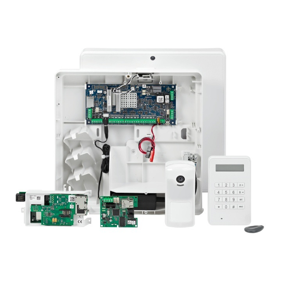
Galaxy Flex Installer Manual System architecture Introduction The Flex alarm system control panel, back-up battery and power supply unit are housed in an ABS plastic housing with swing down lid that is designed for wall mounting. The housing is available in two sizes: M (10 Ah capacity) and L (17 Ah capacity) and can accommodate the following optional modules: GSM/GPRS module Ethernet module (fitted in a peripheral slot) -
Page 10: System Architecture
Galaxy Flex Installer Manual System architecture System architecture Figure 2 shows the full range of peripheral devices that can be connected to the system via the RS485 data bus, the Intellibus, and other specific connection points on the control panel PCB (see PCB layout and connections on page 12). - Page 11 Galaxy Flex Installer Manual System architecture There are three models in the Galaxy Flex range. Flex can support the type and number of modules shown in Figure 2 and the following table: Panel models and quantities Feature or peripheral Flex 20 Flex 50 Flex 100 RS485 Lines...
-
Page 12: Pcb Layout And Connections
Galaxy Flex Installer Manual PCB layout and connections PCB layout and connections Figure 3 shows the control panel PCB layout and detailed connection information. Figure 3 PCB layout and connection... -
Page 13: Section 1: Installation Procedure
Galaxy Flex Installer Manual Planning Section 1: Installation procedure Planning Site the panel near to a source of a.c. power. If GSM/GPRS is fitted, check that the panel location will provide acceptable radio reception. If you intend to use wireless detectors and an RF Portal is fitted to the panel, check that the panel location will provide acceptable radio reception. -
Page 14: Install The Power Supply
Galaxy Flex Installer Manual Install the power supply 3. On the telecoms terminal block (see Figure 3), connect the phone line to the terminals marked LINE A and B. 4. Install the battery, but DO NOT connect. If possible, use a fully charged battery. Install the power supply Safety instructions Fixed wiring and connection to the electricity supply of this product must be carried out and... - Page 15 Galaxy Flex Installer Manual Install the power supply To connect the power supply: ‘L’ version: 17 Ah box ‘M’ version: 10 Ah box Locate the power supply module as shown above (either ‘M’ or ‘L’ version panel). Plug the power supply d.c. output into the pcb. Connect the L, N and E wires of the PSU a.c.
- Page 16 Galaxy Flex Installer Manual Install the power supply Where the mains cable exits the panel, secure it to the panel with a cable tie. DO NOT apply mains power until additional wiring is complete. For installation of peripherals please see Appendix G at the back of this manual The following peripherals are described: Peripheral Description...
-
Page 17: Wire Detectors To Zones
Galaxy Flex Installer Manual Wire detectors to zones Wire detectors to zones Note: Learning wireless detectors is covered on page 27. Zones are the individual input circuits that are fully programmable using the Zones menu ). This section describes how to change zone default settings, how to terminate 52 ent unused zones, and how to connect detectors. -
Page 18: Detector Connection
Galaxy Flex Installer Manual Wire detectors to zones Terminate any unused zones inputs with a 1 k resistor and program them as SPARE (Menu 52.1.x.1=18). If required, reprogram zone configurations and the resistance preset values using the Zone Resistance menu ( 51 ent 46 ent If required, customise each zone to a specific preset using the Resistance Select menu 52 ent 9 ent... -
Page 19: Wire Key Switches
Galaxy Flex Installer Manual Wire detectors to zones Figure 5 Option 10 - End of Line Zone/Detector wiring Multiple detector wiring Multiple detectors can be wired into a single zone when using preset 1 as shown in Figure 6. The maximum number of detectors that can be connected to a single zone is ten. Figure 6 Zone to multiple detector wiring Wire key switches Latching (bi-stable) and spring-loaded (monostable) key switches can be used to set and... -
Page 20: Connect Outputs
Galaxy Flex Installer Manual Connect outputs The wiring of the terminator and keyswitch zone type is shown in the following figure: Figure 7 Terminator and keyswitch zone wiring Connect outputs Outputs are addressed in the same way as the zones. If using on-board outputs, connect and address as follows: Address Function... -
Page 21: Connect The Battery And Mains Power
Galaxy Flex Installer Manual Connect the battery and mains power Connect the battery and mains power The control panel can accommodate one 10 Ah or one 17 Ah battery, depending on version. Ensure that the battery connector leads on the control panel are connected to the correct terminals on the battery. -
Page 22: Install Peripheral Devices
Galaxy Flex Installer Manual Install peripheral devices Using the keypad: Press any key. The following is displayed: Language 1=English Select your language, and then press . The following is displayed: Defaults 1=UK Select the default set to load, and then press . - Page 23 Galaxy Flex Installer Manual Install peripheral devices Configuration A (Single Chain) = End Of Line Resistor fitted Panel Device Device Device Configuration B (Two Chains) = End Of Line Resistor fitted Panel Device Device Device Configuration C (Three or four Chains – Intellibus only) Device = End Of Line Resistor Device...
-
Page 24: Peripheral Power Supply Considerations
Galaxy Flex Installer Manual Install peripheral devices Peripheral power supply considerations Data bus peripherals can be powered from the control panel via additional cores in the data bus cables. If you choose this method, ensure there is sufficient spare power capacity in the panel’s power supply, and consider the voltage drop along the cable. -
Page 25: Connection To The Rs485 Bus
Galaxy Flex Installer Manual Install peripheral devices Figure 10 Power cable spans for two camera PIRs L1 is the distance from the Power Supply to the first camera PIR L2 is the distance between the first and second camera PIR Connection to the RS485 bus Note: Do not connect cameras or an Ethernet module to this bus. -
Page 26: Connection To The Intellibus
Galaxy Flex Installer Manual Install peripheral devices Fit a 680 end-of-line resistor to the end of the bus. Apply power to the system and the devices will be registered automatically Connection to the Intellibus Note: Do not connect any peripherals other than Camera PIRs or the Ethernet module to this bus. -
Page 27: System Assigned Addresses
Galaxy Flex Installer Manual System assigned addresses System assigned addresses The following System zone and module address are defined within the system: Comms module identification Device Module ID Keypad PSTN (on board) Com 1 Ethernet module Com 4 Com 5 GPRS module Com 5 USB port... -
Page 28: Learn Wireless Detectors
Galaxy Flex Installer Manual Learn wireless detectors Learn wireless detectors Wireless Sensors and keyfobs can be learned provide that at least one RF Portal is configured onto the system. Learn new wireless detectors as follows: On the keypad select Batch learn ( 52 ent 3 ent Press to enter Self-Learn mode. -
Page 29: Additional Programming
Galaxy Flex Installer Manual Additional programming Additional programming Use this section as a quick reference to some of the functions you may wish to program or modify. Parameters (51 ent) Entry Time ( ) – defines the user unsetting time 05 ent Exit Time ( ) –... -
Page 30: Users And Access Templates
Galaxy Flex Installer Manual Additional programming Program outputs (53 ent + Output Address) Output Function ( ) – assign an output type 1 ent Descriptor ( ) – name an output (up to 12 characters) 5 ent Output Mode ( ) –... -
Page 31: Additional Services
Galaxy Flex Installer Manual Additional services If no schedule is allocated to a particular group (default) in the list then users will have full access through any doors leading to that group. When a schedule is allocated, access will be granted during the OFF periods of the schedule and denied during the ON periods. -
Page 33: Section 2: Commissioning And Handover
Galaxy Flex Installer Manual View zone information Section 2: Commissioning and handover View zone information Display zones ( ). View information about any selected zone. 21 ent Walk test Select Test All Zones ( ) to perform an audible test. Alternatively, 31 ent 2 ent 2 ent 1 to perform a silent test, press 31 ent 2 ent 1 ent 1... -
Page 34: Full Test
Galaxy Flex Installer Manual Full Test Full Test Use this menu option to select and test up to two zones under full set conditions, including remote signalling. All remaining zones, except for permanently active zones such as PA and Fire, are inactive during the test. To perform a full test: Select Full Test ( 62 ent... -
Page 35: Section 4: Menu Structure
Galaxy Flex Installer Manual Menu access Section 3: Menu structure You can control and setup the Flex system via these two menu structures: Full menu – accessible only by authorized users including the master manager and the engineer. The full menu has a hierarchy of five levels that allow users with the right authority to perform increasingly advanced setup procedures. -
Page 36: Full Menu
Galaxy Flex Installer Manual Menu navigation Full Menu On entering the menu the following option is displayed on the keypad: 10=SETTING [ent] to Select If you scroll from this point you will access the menu items shown in the row, highlighted in grey, in the table below. -
Page 37: Default Codes
48 ent 1 ent 1 ent 1 ent out the next step. Press esc repeatedly to return to the Honeywell banner. Enter the default engineer code, and then press After handover the codes should have been changed and you will need to get a manager or other type 6 user to carry out steps 1 and 2. -
Page 38: Multi-User Access
Galaxy Flex Installer Manual Multi-user access To exit from Engineer Mode: Return to the engineer banner. Enter your engineer code. Press Note: If is pressed during the following system checks, the exit is aborted and the system remains in engineering mode. Before the normal banner is displayed the system performs these checks: That there are no open zones or tampers. -
Page 39: Section 5: System Programming
Galaxy Flex Installer Manual Set using a PIN Section 4: System programming Setting Options Setting and unsetting operation may vary slightly depending on the programming of the parameter Simple Set [51.80]. The following assumes that Simple Set is Enabled. Set using a PIN To Full Set: Press When prompted, type your user code. -
Page 40: Cancel Setting
Galaxy Flex Installer Manual Cancel setting To Part Set: Press When prompted, type your code. Select A for Standard Part Set or B for Night set A=PART SET PART SET B=NIGHT SET ■■■■■■■■ This is similar to the full setting procedure, except only the zones that have the Part or Night attribute enabled are included (refer to the Program Zones [52] option). -
Page 41: Set With Cards/Tags/Fobs
Galaxy Flex Installer Manual Set with cards/tags/fobs Set with a keyswitch A keyswitch starts the setting procedure of each of the groups assigned to the keyswitch zone. At the end of the exit time or when the setting procedure is terminated by a final or push-set zone closing, the entry/exit horn and keypad buzzers become silent for six seconds, then emit two long tones to confirm that the system is set. -
Page 42: Cancel And Reset Alarms And Alerts
Galaxy Flex Installer Manual Cancel and reset alarms and alerts Cancel and reset alarms and alerts Following an alarm in the set state, sounders and strobes are activated. When a fault occurs in the unset state, the keypad emits an intermittent beep and/or displays a visual alert. To cancel an alarm and reset the system: Do one of the following: Type any valid user code (type 2 and above) assigned to the group that has... -
Page 43: Override Faults And Tampers
Galaxy Flex Installer Manual Override faults and tampers If there are multiple alarm causes and/or multiple groups require to be reset, then the alarm cause code only has to be entered once. The user enters the most appropriate code as determined on site. - Page 44 Galaxy Flex Installer Manual Setting features Note: The Show Status indicates the set conditions of groups when the system is set (keypad blank) or unset (normal banner). Show Status does not operate while engineer mode is accessed.
- Page 45 Galaxy Flex Installer Manual Setting features Press again to toggle the display to show the status of the groups individually. To move between each group, press simultaneously. 08:58 TUE 22 NOV A1U Group A1 group A1 is unset Press again to return the keypad to the banner display. Exit time Once the setting routine starts, outputs programmed as Entry/Exit Horn emit a continuous tone.
- Page 46 Galaxy Flex Installer Manual Setting features 2 Groups not set [<],[>] to view Entry time The system begins the unsetting routine whenever a final or entry zone activates. The entry/exit horns pulse slowly indicating that the entry time countdown has started. The user must go directly to the keypad, using the agreed entry route, and unset the system before the entry time expires.
-
Page 47: Sms Remote Control
Galaxy Flex Installer Manual SMS remote control SMS remote control If the Flex system is fitted with a working GSM module the user can control the system by sending special SMS messages to the GSM module’s phone number. Note that control via SMS may not comply with the requirements of EN50131 SMS control must be enabled in menu 56.5.2 Command format... -
Page 48: Menu Options 11-19
Galaxy Flex Installer Manual Omit Zones [11, Quick Menu 0] Menu Options 11-19 Omit Zones [11, Quick Menu 0] Use this option to remove (omit) zones from the system temporarily. Once a zone has been omitted it does not generate an alarm condition (including tamper). Omitted zones are reinstated automatically when the system is unset or reinstated manually when the zone omit option is disabled. -
Page 49: Part Set [13]
Galaxy Flex Installer Manual Part Set [13] Note: The factory default setting allows the timed setting routine to be initiated by entering a valid type 1 user code (or above) and then pressing . By default the key is assigned to the Timed Set function. The key can be reprogrammed by the engineer to perform another function, or to start the setting routine without a code being entered. -
Page 50: Home Set [18]
Galaxy Flex Installer Manual Home Set [18] Home Set [18] The Home Set option either fully sets or part sets the system. The system is: fully set if the exit time is manually terminated via a Final or Push-Set zone operation. night set if the exit time is allowed to expire. -
Page 51: Display Options
Galaxy Flex Installer Manual Display Zones [21, Quick Menu 2] Display options Display Zones [21, Quick Menu 2] When you select Display Zones the first zone in the system is displayed. Press display other zones, or enter a zone number directly. The top line displays: the address. - Page 52 Galaxy Flex Installer Manual Display Log [22, Quick Menu 3] required groups are selected press to access the log. Only the events in the selected groups are displayed. When you access the event log, the most recent event is displayed. Use to scroll through the events.
-
Page 53: System [23]
Galaxy Flex Installer Manual System [23] System [23] Use this option to display an overview of the system configuration. You can scroll through the items shown below, which are displayed using both lines on the keypad screen. Group status U = Unset, S = Set, P = Part Set, and L = Locked-out for each of the groups displayed. -
Page 54: Print [24, Quick Menu 4]
Galaxy Flex Installer Manual Print [24, Quick Menu 4] Print [24, Quick Menu 4] Note: A serial printer must be connected to the panel via a printer interface module. Only information corresponding to the groups assigned to the user is printed. Print Codes [24.1.1] Prints user number and name, type and groups assigned. - Page 55 Galaxy Flex Installer Manual Access Doors [25] representation of each address. By matching the (LED off) and (LED on) on the keyboard to the LEDs on the MAX, you can identify each device on the system. Date [25.4] Use this option to display the events on a specific date. Enter a date using the DD/MM/YY format.
- Page 56 Galaxy Flex Installer Manual Access Doors [25] The Access Door Log print displays in the format of the Event Log and allows information to be accessed. The format is as follows: HH:MM_XXXXXXXXXX_USR_NNN_UUUUUU_MYY_–_ (39 character display) Key: HH:MM = time in hours:minutes (5 characters). The date will be printed only at the beginning of every day, starting at midnight.
-
Page 57: Test Options
Galaxy Flex Installer Manual Walk Test [31, Quick Menu 5] Test options Walk Test [31, Quick Menu 5] Walk Test menu 31 = Walk Test û 1 = View – not used 2 = Activate û 1 = Silent û 1 = Test all Zones 2 = Selected Zones 2 = Audible... -
Page 58: Outputs [32]
Galaxy Flex Installer Manual Outputs [32] Note: PA, PA Silent, PA Delay, PA Silent Delay and Fire are not included in the test when is used to include all zones. The response time of the zone circuits is reduced to 20 ms (40 ms for RF RIOs) for the duration of the walk test to detect loose connections or damaged wiring. -
Page 59: Modify Options
Galaxy Flex Installer Manual Time/Date [41, Quick Menu 6] Modify Options Time/Date [41, Quick Menu 6] The Time/Date option can be accessed and modified by type 6 codes, the engineer and the remote code. If any groups are locked, then the time and date cannot be modified. Modifying the time and date Use this option to modify the system time and date. -
Page 60: Codes [42, Quick Menu 7]
Galaxy Flex Installer Manual Codes [42, Quick Menu 7] Codes [42, Quick Menu 7] Codes menu 42 = Codes û 1 = User Codes (enter a user code) û 01 = Modify PIN (4, 5, 6 digit PIN) û 02 = Modify Level (0 to 6) û... - Page 61 Galaxy Flex Installer Manual Codes [42, Quick Menu 7] Default Codes The system has three default codes: Manager, Engineer and Remote User. No. of Codes Manager Engineer Remote User Default PIN User No. Default PIN User No. Default PIN User No. 1234 112233 543210...
- Page 62 Galaxy Flex Installer Manual Codes [42, Quick Menu 7] Scroll to the required option or type an option number, and then press ent. The options are described below. Standard user access Modify PIN [42.1.User code.1] PINs identify each user to the panel and permit users to operate the system. Use this option to assign a PIN to a selected user, or modify an existing PIN.
- Page 63 Galaxy Flex Installer Manual Codes [42, Quick Menu 7] A single entry of a dual code, without a second dual code entry within 60 seconds, is recorded in the event log as an Illegal Code; all outputs programmed as Illegal Code are activated.
- Page 64 Galaxy Flex Installer Manual Codes [42, Quick Menu 7] To assign a level to a user: Type the level to be assigned. Press EN50131-1 Level Access Availability Level † Guard Entered into event memory – no other option † Guard Can only set the system and change own PIN †...
- Page 65 Galaxy Flex Installer Manual Codes [42, Quick Menu 7] To control the menu options available to each user level refer to Menu Access [68]. You can allow users to access menu options that their code types are not, by default, authorized to access.
- Page 66 Galaxy Flex Installer Manual Codes [42, Quick Menu 7] Group options Single Group A user can be assigned to any single group. In this case type 2 and above users can access, set and unset the single group only. Multiple Groups Users can be allocated to more than one group in which case access and operation is collective;...
- Page 67 Galaxy Flex Installer Manual Codes [42, Quick Menu 7] For access control cards, when the serial number is not printed on the card, the card number can be learned using the Add Batch [42.2.1] option. MAX Function [42.1.User code.7] The card/fob/tag/button can be assigned a single menu option. The user must be authorized to access the menu option assigned to the MAX, either by the user level assigned or the Menu Access [68] option.
- Page 68 Galaxy Flex Installer Manual Codes [42, Quick Menu 7] Template [42.1.User code.9] An Access Template controls the areas to which a user has access, and also the access times. Once a template is created in Access Template [45.6] it can be assigned to multiple users. This eliminates repetitive programming of common door access rights for multiple users.
- Page 69 Galaxy Flex Installer Manual Codes [42, Quick Menu 7] Camera [42.1.User code.11] 1=During Exit Use this option to associate a camera with a user so that the user’s image is captured when setting the system. The options are: 0=Disabled, 1=Enabled. 2=Duress Use this option to define a photo sequence that will be taken when the Duress code is used.
-
Page 70: Summer [43, Quick Menu 8]
Galaxy Flex Installer Manual Summer [43, Quick Menu 8] User Notify [42.4] Use this option to send selected events to a maximum of three different mobile phone numbers via SMS messaging. This can be configured either using the Telecoms module or using the GSM module where fitted. - Page 71 Galaxy Flex Installer Manual Trace [44] Press the number of the group to be displayed. The N below the selected group changes to a Y, and then press If more than one group is selected, or the user does not have group choice, then the trace for the group with the most recent alarm activation is displayed.
-
Page 72: Timer Control [45]
Galaxy Flex Installer Manual Timer Control [45] Timer Control [45] Timer control menu 45 = Timer Control û 1 = View û 1 = Weekly Sched. û 2 = Timer Outputs 3 = Autoset û 2 = Holidays û 1 = Holiday01 1 = Name, 2 = Modify Dates û... -
Page 73: Group Omit [46]
Galaxy Flex Installer Manual Group Omit [46] Holidays [45.2] Use this function to allocate up to 10 holiday calendars, depending on model (see Table 1 on page 11). Timers [45.3] If Timer Access [51.43] is enabled these sub-options are available for each weekly schedule (Weekly01 to Weekly04): 1=Name 2=Status... - Page 74 Galaxy Flex Installer Manual Group Omit [46] When you select the option the groups assigned to the user code and keypad are displayed as well as the omit status of each group (Y below the group indicates that it is omitted, N indicates that it is not omitted).
-
Page 75: Remote Access [47]
Galaxy Flex Installer Manual Remote Access [47] Remote Access [47] Use this option to control all site initiated remote connectors. Remote Access menu 47 = Remote Access û 1 = Service û 0 = PSTN û 0 = Direct Access 1 = Call Back-1 to 5 = Call Back-5 û... - Page 76 Galaxy Flex Installer Manual Remote Access [47] û 3 = Terminate Idle – Idle Time 10 (0-60 mins) û 4 = Conn Retry û 1 = Retry Interval 30 (0-60) mins û 2 = Retry Duration 06 (0-24) hours 3 = Redial Mode û...
- Page 77 Galaxy Flex Installer Manual Remote Access [47] PSTN Direct Access [47.1.0.0] GSM Direct Access [47.1.1.0] GPRS Direct Access [47.1.2.0] Ethernet Direct Access [47.1.3.0] When you select one of these options, a 40 minute remote access period is enabled on the panel.
- Page 78 Galaxy Flex Installer Manual Remote Access [47] If site programming changes send the new programming to the downloader. On a predetermined schedule, activate an automatic periodic upload. On a predetermined schedule, activate an automatic remote routine inspection. Note: The Auto Service function works for both the Internal Telecoms and the Ethernet module.
- Page 79 Galaxy Flex Installer Manual Remote Access [47] Auto Service Timers Sync Schedule [47.4.2.3] Use this option to program the panel to automatically connect to the remote servicing application and upload the latest panel programming during the off-peak window. The period of time between connections can be set from 0 to 365 days. The default setting is 0, which disables the option.
- Page 80 Galaxy Flex Installer Manual Remote Access [47] Control Upload Eng Prog [47.4.5.1] Initiates a connection when engineer programming has been modified. Control Upload User Prog [47.4.5.2] Initiates a connection when user programming has been modified. Control Upload Either [47.4.5.3] Initiates a connection when engineer or user programming has been modified. Remote Maint [47.4.6] Use this option to control the mode for automatically initiating communications for remote routine inspection and maintenance.
- Page 81 Galaxy Flex Installer Manual Remote Access [47] when the Schedule [47.4.6.1] option is greater than 0 and when the Code Only [47.4.6.2.1] option is enabled. Delay Time [47.4.9] This is the time that the panel delays for incoming information from the remote servicing package.
-
Page 82: Engineer Access [48, Quick Menu 9]
Galaxy Flex Installer Manual Engineer Access [48, Quick Menu 9] Engineer Access [48, Quick Menu 9] This option enables a manager to authorize an engineer to access the system. Engineer System Access [48.1.1] By default the assigned engineer code is programmed as dual. This prevents the engineer from accessing engineering mode unless authorized to do so by a type 6 user, normally a manager with a valid code. -
Page 83: Engineer 1 Options
Galaxy Flex Installer Manual Parameters [51] Engineer 1 options Parameters [51] Use this option to modify the system functions. to select an option, or enter the two digit parameter number and press to increase, or to decrease, the values assigned to the parameter. Press to accept a new value and return to the previous menu level. - Page 84 Galaxy Flex Installer Manual Parameters [51] Parameter list Parameter Groups Parameter Groups 01 = Bell Time 50 = Trigger Mod not available 02 = Bell Delay 54 = Keypad Access not available 03 = Abort Time 55 = Confirm not available 04 = Exit Time 56 = Force Restore not available...
- Page 85 Galaxy Flex Installer Manual Parameters [51] Bell Time [51.01] Use this option to set the bell time on activation. The default is 15 minutes and the range is 0 to 30 minutes. Use 00 minutes to set the bell time to infinity. You can assign a different value to each group.
- Page 86 Galaxy Flex Installer Manual Parameters [51] If a valid code is entered within the programmed abort time: If an abort output/channel is allocated to the alarmed group: – The Abort signal is sent. – The intruder condition is not restored. –...
- Page 87 Galaxy Flex Installer Manual Parameters [51] Infinite Exit Time Assign a value of 000 seconds to set the Exit Time to infinity. An Exit terminator activation (Final or Push-set zone) is required to complete the setting of the system. The infinite Exit Time is normally used with a Push-set zone to terminate the setting and an Entry zone to start the unsetting procedure.
- Page 88 Galaxy Flex Installer Manual Parameters [51] 6 for the manager. 7 for the engineer. You can assign a different value to each group. Note: This option is affected by Reduced Resets [51.55.3]. The panel only requests Engineer Level Reset if alarms have been signalled via the Communication Module and the appropriate level reset is set to 7.
- Page 89 Galaxy Flex Installer Manual Parameters [51] If the Local Part parameter is set to 1 (enabled) the Intruder outputs activate if an alarm condition occurs when the system is part set. Option 2 (SIA part off) is identical to option 1 with the exception that when the alarm format of the telecom module is set to SIA, part setting and unsetting of the system is not signalled to the ARC.
- Page 90 Galaxy Flex Installer Manual Parameters [51] System Text [51.15] Use this option to assign two text strings to the system: press 1 to select the System ID or 2 to select the Panel Location. 1=System ID 16 character identification of the system. Use this when connecting to Remote Servicing software.
- Page 91 Galaxy Flex Installer Manual Parameters [51] Language [51.17.3] Use this option to select the keypad display language. Press to change the display immediately. Cold Start [51.17.4] Use this option to set all defaults back to factory settings. Stop Set [51.18] Use this parameter to prevent the system from set override if there is a communication or power fail condition at the time of starting the setting procedure.
- Page 92 Galaxy Flex Installer Manual Parameters [51] PA Reset [51.22] Use this option to select the user type that can reset the system following a PA activation. A remote code can also change this option. The default type is 3 and the range is 3 to 5 for the user.
- Page 93 Galaxy Flex Installer Manual Parameters [51] 1=ENABLED Switches the printer to online mode and requires a continuously connected printer. Events are printed as and when they occur. The events printed are controlled by Online Level [51.29]. Note: If Online Print is enabled, the event log and other options will not be printed at the user’s request.
- Page 94 Galaxy Flex Installer Manual Parameters [51] Either the engineer or remote user code can select the Secure Code parameter. On selecting this parameter the secure code equivalent to the current engineer code must be entered to confirm the selection. Only the remote user code (or a cold start - erasing all programming details) can cancel it.
- Page 95 Galaxy Flex Installer Manual Parameters [51] To select a preset, enter an option number from the tables below: Option Double balanced End of line Split resistance 1k fault 1k fault 1k N/O 0k N/C 2k2, 4k7 Table 2 Resistance values The operating range for each resistance value is shown in Appendix H: Resistance tables on page 255.
- Page 96 Galaxy Flex Installer Manual Parameters [51] 1=No of Alarms The total number of zone activations signalled in any one set period. The selectable values are 0 to 10 where 0 is unlimited. 2=Unset Limit The number of activations logged from any one zone in any one unset period.
- Page 97 Galaxy Flex Installer Manual Parameters [51] 0=Disable Exits Exit type zones will only cause unconfirmed intruder alarms. They will not contribute to the two activations required for a confirmed alarm. 1=Enable Exits After the expiry of the entry delay, activation of an exit type zone will be identical to an intruder zone.
- Page 98 Galaxy Flex Installer Manual Parameters [51] [51.57] Not used Power Alarm [51.58] Enable this parameter to allow the Bells, Strobe and Horn outputs to activate when there is an a.c. failure and the system is set. The default is 0. Part Tone [51.59] Enable this parameter to change the setting tone for a part set.
- Page 99 Galaxy Flex Installer Manual Parameters [51] RF Stop Mode [51.60.7] This option controls whether, and how, an RF fault prevents the panel from being set. There are three options: 0=Disabled An RF fault will not prevent setting 1=Warning If there is a failure the user will get a warning but can continue to set 2=Auto Check If there is a failure the system cannot be set until the zone(s) have been activated...
- Page 100 Galaxy Flex Installer Manual Parameters [51] Lockout Tamper [51.62.2] Use this option to set the number of invalid code attempts that can be made before system tamper occurs. The default is 15 and the range is 0 to 21. 0 disables the function. Banner Alerts [51.63] Use this option to program whether system alerts are displayed on the keypad banner.
- Page 101 Galaxy Flex Installer Manual Parameters [51] SWDC Set Dly [51.70] Enable this parameter to delay the indication of open zones at the start of a set sequence while latching sensors are being reset. This affects indication via keypad text and sounders. If there are no outputs programmed as Switch DC (function 08), there is no delay at the start of the set sequence.
- Page 102 Galaxy Flex Installer Manual Parameters [51] 03=Pre-alarm 1=No. of photos. (1 to 10, the default is 4). 2=Interval defines the time delay between each photo (200 to 1000 ms). The setting range is 0 to 8. 04=Post Alarm 1=No. of photos. (1 to 10). 2=Interval defines the time delay between each photo (200 to 1000 ms).
- Page 103 Galaxy Flex Installer Manual Parameters [51] User Test [51.84] Use this option to enable the comm. test facility via the keypad hotkey and 0. This allows the user to activate a comms test to the ARC. There are two options: 0=Disabled, 1=Enabled.
- Page 104 Galaxy Flex Installer Manual Parameters [51] Hide Com Flts [51.90] Enable this option to prevent line fail, heartbeat fails and communication faults from being sent and from being indicated on the displayed. There are two options: 0=Disabled, 1=Enabled. Log IPCheck [51.91] Use this option to define if the low-level polling on the Ethernet and GPRS module should be logged in the diagnostic log when a message fails to be acknowledged.
-
Page 105: Program Zones [52]
Galaxy Flex Installer Manual Program Zones [52] Program Zones [52] Program zones menu 52 = Program Zones û 1 = Zones – Select a zone, and then press ent Select an attribute (see table below) If you select 1 = Function, scroll to a zone function or type its number directly, for example 19 to display 19 = Fire û... - Page 106 Galaxy Flex Installer Manual Program Zones [52] Press to toggle the descriptor to reveal the status of the chime, omit and part attributes. If the attribute is enabled, the initial attribute letter is displayed, if it is disabled, a dash (–) is shown.
- Page 107 Galaxy Flex Installer Manual Program Zones [52] Note: Library words are a maximum of 12 characters and upper case only. 3=Chime Enable the Chime attribute to make a zone chime momentarily whenever it is opened while the system is unset. The Chime attribute defaults to 0 (disabled) for all zone functions. to toggle the status of the Chime attribute, and then press to accept the programming.
- Page 108 Galaxy Flex Installer Manual Program Zones [52] 7=Custom SIA Use this option to change a zone’s SIA mnemonic. The default is the standard SIA mnemonic for each zone type. The customisable mnemonics are shown in the following table: Event text Description Alarm Closed Omit Unomit Troub ResTr.
- Page 109 Galaxy Flex Installer Manual Program Zones [52] 10=Group Note: The Groups attribute is only available if groups have been enabled on the system (refer to option Options [63]). The Group attribute allows the zone to be assigned to a single group on the system. All zones default to Group 1.
- Page 110 Galaxy Flex Installer Manual Program Zones [52] 11=RF options These sub-options are available: 1=Serial No. The serial number of the wireless detector associated with this zone is displayed if this already exists. Press to view the serial number in hexadecimal format. To learn a new detector, program the serial number manually or use Self-Learn mode.
- Page 111 Galaxy Flex Installer Manual Program Zones [52] Scroll through the available channels, and then press to select the available audio channel. 14=Fire Confirm Use this attribute to enable this zone to be used as a fire confirm. A Fire zone with this attribute enabled must be activated first.
- Page 112 Galaxy Flex Installer Manual Program Zones [52] 01 Final Zones programmed as Final initiate the unsetting procedure and terminate setting procedure; opening the Final zone when the system or group is set starts the entry timer; opening and then closing the Final zone during the exit procedure sets the system or assigned groups, providing all the zones are closed.
- Page 113 Galaxy Flex Installer Manual Program Zones [52] normally used in conjunction with a Push Set zone, which acts as the exit terminator for the setting procedure. Pressing when programming an Entry zone doubles the entry time of the group. Opening an Entry zone during the exit time is reported on the keypad as an open zone, and the entry/exit horns bleep rapidly to indicate that the zone is open.
- Page 114 Galaxy Flex Installer Manual Program Zones [52] The Part attribute of the Keyswitch function defaults to 0 (disabled) and the standard Keyswitch function full sets the system. To part set the system using the Keyswitch, enable the Part attribute. Note: The operation of a Keyswitch zone can be extended to the setting and unsetting of multiple groups by pressing when assigning a group to the zone.
- Page 115 Galaxy Flex Installer Manual Program Zones [52] When the system is full set operation is identical to the Exit zone function. When the system is part set operation is identical to the Entry zone function. Pressing when programming a Part Entry zone doubles the entry time of the group. 13 PA The PA (Personal Attack) function is continuously operational.
- Page 116 Galaxy Flex Installer Manual Program Zones [52] 18 Spare The Spare function allows any unused zones to be ignored. The resistance readings from the circuit, including the tamper conditions, do not activate an alarm condition. Note: We recommend that all unused zones are programmed as Spare and that a 1 k 1% resistor is connected across each of these zones.
- Page 117 Galaxy Flex Installer Manual Program Zones [52] If the Line Fail zone is active at the point of setting, a warning message is displayed. The user can choose to continue or abort the setting procedure. It is also possible to prevent the system setting if the Line Fail is active by enabling the Stop Set parameter (option 51.18).
- Page 118 Galaxy Flex Installer Manual Program Zones [52] This function is designed to permit a remote signal, for example REDCare’s Return Path Signalling feature, to reset the system following an alarm condition. 40 Bell Fail This zone type is for bells that have diagnostic capabilities and failure outputs. If activated, it causes fault for any bell failure condition.
-
Page 119: Program Outputs [53]
Galaxy Flex Installer Manual Program Outputs [53] Program Outputs [53] Use this option to modify the programming of the outputs on the system. You can also change the attributes of the outputs. The programmable options are: Attributes Description 1 = Output Function Assign output type 2 = Output Mode 1 = Latch - requires valid code to reset... - Page 120 Galaxy Flex Installer Manual Program Outputs [53] The valid keypad addresses and the respective output addresses are indicated in the following table: Line Address Output Addresses 0 – 7 10 – 17 Table 7 Addresses of Valid Keypad Outputs Attributes to step through the attributes, or enter an attribute number (1 to 7).
- Page 121 Galaxy Flex Installer Manual Program Outputs [53] 4=Diag Recording Enable this attribute so that it is used during the diagnostic test (see Record [61.2.3]). This test can also be carried out remotely. 5=Descriptor Use this attribute to assign a descriptor of up to 12 characters to each output. 6=Control Use this attribute to allow users to control the state of certain panel outputs from the TouchCenter.
- Page 122 Galaxy Flex Installer Manual Program Outputs [53] To assign the Group Status conditions, press when selecting the groups. A solid block is displayed on the bottom line as well as the current Status. Press the relevant number to toggle the status of the groups, and then press to accept the programming.
- Page 123 Galaxy Flex Installer Manual Program Outputs [53] Output Functions This table shows all the outputs and the zone functions and conditions that result in their activation. Output Functions Bells Strobe Intruder Tamper Reset Switch Spare Ready Security AC Fail Batt Low Zone Function Final –...
- Page 124 Galaxy Flex Installer Manual Program Outputs [53] Output Functions Fire Horn Part Confirm Line Video Comm DLYD Timer-A Timer-B Horn Fail Fail Fire Re-arm Zone Function Final – – – – – – – Exit – – – – – –...
- Page 125 Galaxy Flex Installer Manual Program Outputs [53] Output Functions Zone Custom Custom Reset Fail Duress Illegal Abort Unset Pre- Autoset Link Omit Code Late Early Warn 51-55 Zone Function Final – – – – – – – – – – Exit –...
- Page 126 Galaxy Flex Installer Manual Program Outputs [53] Output Functions Bell Fail Fault Bell Comms Listen–in Fire Confirmed Super Test Test Reset Fire Alarm Final – – – – – – – Exit – – – – – – – Intruder –...
- Page 127 Galaxy Flex Installer Manual Program Outputs [53] 01 Bells (Latch) This output is activated on a full alarm event when the system is set, and is subject to the Bell Time, Bell Delay and No. Re-arm parameters. 02 Strobe (Latch) This output is activated on a full alarm event during the set state, and is subject to the Bell Delay.
- Page 128 Galaxy Flex Installer Manual Program Outputs [53] 11 Spare (Latch) Use this function for outputs that are not being used on the system. 12 Ready (Reflex) The Ready output is active when all zones in the system (group) are closed, and activates in both the unset and set conditions.
- Page 129 Galaxy Flex Installer Manual Program Outputs [53] It provides a system status indication during unsetting and setting. The indicated states are as follows: General Alarm On 500 ms. Off 500 ms Clear to Exit Continuous Exit interrupted On 100 ms. Off 100 ms 75% Exit Time On 200 ms.
- Page 130 Galaxy Flex Installer Manual Program Outputs [53] 27 Fire Delay (Latch) This output is activated whenever a Fire zone is activated. Activation is delayed subject to the 51.03=Abort Time parameter. The Fire Delay output is not subject to the Re-arm parameter.
- Page 131 Galaxy Flex Installer Manual Program Outputs [53] 40 Fail Set (Latch) Fail Set is activated if the system (or assigned groups) fails to set within the time assigned in 35=Fail to Set (refer to Parameters [51]). 41 Duress (Latch) This function is activated by any code assigned as a Duress Code using Codes [42]. The output is not subject to the Re-arm parameter.
- Page 132 Galaxy Flex Installer Manual Program Outputs [53] 51 – 55 Link A – E (Reflex) Link outputs have no inherent function. They are designed for use with Links [54] to provide the engineer with a means of activating a specific output address. Link outputs can be activated by any of the link option sources.
- Page 133 Galaxy Flex Installer Manual Program Outputs [53] 82 Fire Reset (Pulse) This output is used to reset latching fire sensors which require removal of power in order t oreset them following activation. The negative power supply to the sensor should be wired to the Fire Reset output.
-
Page 134: Links [54]
Galaxy Flex Installer Manual Links [54] Links [54] Links offer a powerful method of interconnecting zones, output functions, codes, keypads, and MAX modules. When you create a link between one of the source types and a valid destination type a links table is constructed. Activating the source of a link activates the destination and this can be used to switch outputs on and off and to omit zones, codes, and keypads from the system. - Page 135 Galaxy Flex Installer Manual Links [54] Source Type * Modifier Example Notes Display a) Not Used – This link is not operational b) Zone Address *1014 When the zone is opened the link is active. When the zone is closed the link is inactive. *1014 When the zone opens the first time, the link is activated.
-
Page 136: Soak [55]
Galaxy Flex Installer Manual Soak [55] Soak [55] Use the Soak option to test selected zones for a period ranging from 1 to 14 days. Program the Soak Time [51.16] before starting a soak test. Zones that activate on soak test do not cause alarms but are recorded in the event log and are reported to type 2 (and above) users when the system is unset. -
Page 137: Communications [56]
Galaxy Flex Installer Manual Communications [56] Communications [56] Use this option to program the panel communications. Menu structure The methodology behind communications programming is to define: a set of messages (Report) that must be sent. the list of destinations (receivers) for the messages. Programming is split into two main sections –... - Page 138 Galaxy Flex Installer Manual Communications [56] Basic alarm signalling setup requires the following steps only. To configure one receiver: In the 56.1.1=Receivers menu, select a receiver, for example Receiver 1: Select a path (the default is PSTN). Program the destination, for example a phone number. Select the format, for example SIA or Contact ID.
- Page 139 Galaxy Flex Installer Manual Communications [56] DTMF reporting DTMF reporting is an alternative to ARC reporting, but is specifically for DTMF/Fast format reporting. Use this section in place of the ARC Report if alarm signalling using the DTMF format. IP Check This function, when enabled, allows the system to check the availability of the IP reporting path of any configured IP modules that are in the ARC reporting sequence through regular polling.
- Page 140 Galaxy Flex Installer Manual Communications [56] ARC Notify [56.1] û 1 = Receivers û 1 = Receiver 1 û 1 = PSTN û 1 = Destination – Enter phone no. û 2 = Format û 1 = DTMF û 2 = SIA û...
- Page 141 Galaxy Flex Installer Manual Communications [56] ARC Notify [56.1] (continued) û 2 = Reports û 1 = ARC û 1 = Account No û 2 = Triggers Select a Trigger Event (01 to 19) û 1 = Status (0 = Disabled, 1 = Enabled) 2 = Groups (if enabled) û...
- Page 142 Galaxy Flex Installer Manual Communications [56] Receiver Destination [56.1.1.receiver.path.1] (excluding USB) Enter a phone number for PSTN and GSM, and enter an IP address for GPRS and Ethernet. If configuring GPRS or Ethernet, after entering the IP address, press to configure the Port No.
- Page 143 Galaxy Flex Installer Manual Communications [56] 1 – as level 0 plus 6 digit accounts. 2 – as level 1 but with event modifiers. 3 – as level 2 but with text descriptions. Microtech [56.1.1.receiver.path.2.3] (PSTN, GSM) Microtech [56.1.1.receiver.path.2.2] (GPRS, Ethernet) Microtech [56.1.1.receiver.path.1.1] (USB) Microtech format is a protocol that transmits detailed point identification information to a computer that has the Alarm Monitoring software installed.
- Page 144 Galaxy Flex Installer Manual Communications [56] † In GPRS this is labelled 2=Account No. ARC Reports The following menu items are used to program ARC, Aux 1, Aux 2, Aux 3 and DTMF event Reports. ARC Report [56.1.2.1] Use this option to program the ARC alarm reporting parameters. 1=Account No This is the site identifier.
- Page 145 Galaxy Flex Installer Manual Communications [56] Triggers [56.1.2.1.2] When you select the option, the first trigger event is displayed (see Table 10 for a list of available triggers). These are the events and alarms that are transmitted to the ARC or computer.
- Page 146 Galaxy Flex Installer Manual Communications [56] Comm Fail Time [56.1.3] Use this option to set the length of time that the system has available to get any message to the ARC via all the programmed paths before the COMM FAIL message event is generated and recorded in the event log.
- Page 147 Galaxy Flex Installer Manual Communications [56] User Notify [56.2] This section defines messages than can be sent directly to an end user’s mobile phone. û 1 = Mobile No 1 û 2 = Mobile No 2 û 3 = Mobile No 3 û...
- Page 148 Galaxy Flex Installer Manual Communications [56] Module config [56.3] This section allows alterations to be made to the characteristics of the different communications modules. û 1 = PSTN û 1 = Line Fail (0 = Disabled, 1 = Enabled) û 2 = No.
- Page 149 Galaxy Flex Installer Manual Communications [56] PSTN Line Fail [56.3.1.1] The Telecom module continually monitors the telephone line to which it is connected. Use this option to select the line monitoring conditions that result in a LINE FAIL event being reported and recorded in the log.
- Page 150 Galaxy Flex Installer Manual Communications [56] period the panel will try to connect to network 1 again. The timeout range is 1 min to 7 days (default 15 mins). GPRS Line fail [56.3.2.2.3] This option monitors the availability of the GPRS network. If the network is lost for an extended period, a Line fail condition is generated.
- Page 151 Galaxy Flex Installer Manual Communications [56] Note: For installation fault finding when setting up a GSM or GPRS connection, please see the Diagnostics.menu [61.1.6.5]. For a quick guide to setting up the GSM/GPRS module, see the GSM module section in Appendix G. GSM/GPRS SIM PIN [56.3.2.6] This is the PIN to access the SIM card (if required).
- Page 152 Galaxy Flex Installer Manual Communications [56] Remote Service [56.4] û 1 = Access Period û 1 = Off û 2 = All Unset û 3 = Any Set 4 = Any Time û 2 = Direct Access û 1 = PSTN (0 = Disabled, 1 = Enabled) û...
- Page 153 Galaxy Flex Installer Manual Communications [56] Call Back [56.4.3.call back number] Up to five telephone numbers or IP addresses can be programmed with which Remote Servicing can instruct the panel to call back. Each telephone number can be programmed to use PSTN or GSM and each IP address can be programmed to use GPRS or Ethernet.
- Page 154 Galaxy Flex Installer Manual Communications [56] Audio [56.6] Use this option to setup Audio Transmission to allow audio verification of an alarm. Each system zone can be assigned one audio channel, each with a maximum of three microphones. Following an alarm transmission over PSTN, you can program the panel to route recorded audio from the time of the alarm activation, and live audio, direct to the Alarm Receiving Centre.
- Page 155 Galaxy Flex Installer Manual Communications [56] Engineer Test [56.7] Use this option to verify that an ARC is receiving transmissions via a particular communications path (setup in 56.1.1). You can also test all Receivers as once (select 10=All receivers). On selecting the option this warning message is displayed on the keypad: WARNING!!! SEND MESSAGE ent=...
-
Page 156: System Print [57]
Galaxy Flex Installer Manual System Print [57] System Print [57] Use this option to print system programming details. There are 2 options: System Print menu 57 = System Print 1 = Printer Module û 01 = System Data [23] û 02 = Codes [42] û... -
Page 157: Keypad [58]
Galaxy Flex Installer Manual Keypad [58] Keypad [58] You can assign individual attributes to each keypad to control how each responds. On selecting the Keypad option, details of the first keypad connected to the system are displayed. keypad address option 1 option 2 flashing cursor if this is the viewed keypad... - Page 158 Galaxy Flex Installer Manual Keypad [58] Buzzer Mimic [58.3] Use this option to program the keypad buzzer to mimic the function of the programmed keypad output (refer to Program Outputs [53]). The default function of the keypad output is entry/exit horn and the default Mimic defaults to On, therefore the keypad buzzer operates as an entry/exit horn at factory setting.
- Page 159 Galaxy Flex Installer Manual Keypad [58] PA Mode [58.7] You can programme the PA hotkeys as follows: 1=Instant The hotkeys activate the PA alarm instantly. This is the default setting. 0=Monitor Enables the PA hotkeys to be used as a hold-up monitor as described below. 0=Monitor In this mode the PA hotkeys start a monitor timer (the time period is set using Hotkey Mon [51.85]).
-
Page 160: Quick Menu [59]
Galaxy Flex Installer Manual Quick Menu [59] Entering a user code, assigned to all groups on a keypad, which is only assigned to a single group, allows access to all of the user’s groups. The user is not restricted by the groups that are assigned to the keypad as long as there is one group common to both. - Page 161 Galaxy Flex Installer Manual Quick Menu [59] 0=OMIT ZONES Option=[11] full menu option number user type (user level) To modify the quick menu: Type, or navigate to, a quick menu number, and then press Type, or navigate to, a full menu number (11 to 72), and then press To delete a quick menu option: =NOT USED is displayed.
-
Page 162: Engineer 2
Galaxy Flex Installer Manual Diagnostics [61] Engineer 2 Diagnostics [61] Use this option to run these diagnostic tests: the communication integrity between the panel and modules voltage measurements resistance measurements module version checks panel memory checks fuse checks This option is split into these sections: Latest: providing real time diagnostic information for the system. - Page 163 Galaxy Flex Installer Manual Diagnostics [61] 6=COMM MODULES the communication level between the panel and the Int Telecoms, Ethernet, GSM/GPRS, and the Audio Module. For each module, the # key gives additional information. Audio Module press # Audio Module 100% CM08 V1.0 100% CM08 13.72V To access MUX module diagnostics, press when the audio interface diagnostics are...
- Page 164 Galaxy Flex Installer Manual Diagnostics [61] 3=RIO Comms snapshot value from last test. 4=PSU Comms snapshot value from last test. 5=MAX Comms snapshot value from last test. 6=COMM Modules snapshot value from last test. 7=Zones snapshot value from last test. The key allows printing of results.
- Page 165 Galaxy Flex Installer Manual Diagnostics [61] 1=Low Sig Level 2=Noise Level 3=Low Battery Diagnostic log [61.4] To help you trace intermittent faults this event log records minor failures and degradations in performance, for example a lower than normal signal strength or a higher than normal zone resistance.
-
Page 166: Full Test [62]
Galaxy Flex Installer Manual Full Test [62] Full Test [62] Use this option to select and test two zones under full set conditions. Activating the selected zone results in a full alarm condition, including remote signalling. Constantly active zones (Security, PA, and Fire) remain active throughout the Full Test. An activation generates the appropriate local or full alarm depending on the zone. -
Page 167: Options [63]
Galaxy Flex Installer Manual Options [63] Options [63] Use this function to divide the system into group subsystems. Options Menu 63 = Options 1 = Groups û 1 = Group Mode û 0 = Disabled 1 = Enabled û 2 = Setting Logic û... - Page 168 Galaxy Flex Installer Manual Options [63] Note: If this option is selected when group mode is re-enabled all previous group programming is restored. However, while group mode is disabled, a zone not programmed to group A1 will not operate normally on the system. We strongly recommended that, whenever possible, groups are always reset to A1 when disabling groups.
- Page 169 Galaxy Flex Installer Manual Options [63] Group Name [63.1.3] Use this option to assign a name of up to 12 characters to each of the groups. Names are made up from the character set and/or library options. To name a group: Select the Group Name option.
- Page 170 Galaxy Flex Installer Manual Options [63] Group Name Display When viewing the groups assigned to an option, for example user code or outputs, you can press together to display the groups individually. The keypad displays the group number, name and the status of the particular option being displayed. Press to toggle the status of the group.
-
Page 171: Assemble Zone [64]
Galaxy Flex Installer Manual Assemble Zone [64] Assemble Zone [64] The Assemble Zone option allows 2 zone functions to be customised to the user’s requirements; these are the 1 Custom-A and 2 Custom-B zones. Once a custom zone function has been assembled, it is assigned to zones using Program Zones [52]. Programming a Custom Zone The flexibility of this menu option allows for an extensive range of possibilities. - Page 172 Galaxy Flex Installer Manual Assemble Zone [64] 4=Set/Unset the output is activated by the custom zone when the system is both set and unset. Select the output types to be assigned by pressing the keys or by entering the number of the required output type, and then assign the required status. When all of the output types have been selected, press to return the previous menu level.
- Page 173 Galaxy Flex Installer Manual Assemble Zone [64] Log [64.4] This attribute determines which custom zone activations are logged. On selecting Log the current selection is displayed. To change the selection press the # key, this toggles between the Log options: Disabled the custom zone activations are not logged.
- Page 174 Galaxy Flex Installer Manual Assemble Zone [64] . Full Set Disabled is displayed. 13. Press . Full Set Alarm is displayed. 14. Press . Status is displayed. 15. Press . Setting is displayed. 16. Press 17. Press to select this option. Begin Set Disabled is displayed. 18.
-
Page 175: Timers [65]
Galaxy Flex Installer Manual Timers [65] Timers [65] Timers Menu 65 = Timers û 1 = Weekly Schedule û 1 = Weekly01 û 1 = Name (12 alpha-numeric) û 2 = Status û 3 = Events Use A or B to select timer, then press ent W1-4 *** **:** **:**... - Page 176 Galaxy Flex Installer Manual Timers [65] The Flex control panel provides programming of timer schedules on a weekly basis. Each event corresponds to an ON or an OFF time. The state of the schedule is ON or OFF depending on the last event that was reached. Timers can be assigned to: Individual users to disable them Individual doors to lock them...
- Page 177 Galaxy Flex Installer Manual Timers [65] Programming Timer Events Select the Events option. The programmed status (if any) of the first timer is displayed. If the timer has not been programmed the keypad displays the following information: first timer W01*** *** **:** To enter a new timer program for W01: Press to select the timer.
- Page 178 Galaxy Flex Installer Manual Timers [65] Use the keys to select the required day or days and press to accept the programming and return to the previous menu level: 1=MON; 2=TUE; 3=WED; 4=THU; 5=FRI Timer Outputs [65.2] Once the times have been programmed and the Status is set to 1=On, the Timer-A or Timer- B outputs types 29 and 30 are activated at the On times and deactivated at the Off times programmed in Weekly Schedule [65.1].
- Page 179 Galaxy Flex Installer Manual Timers [65] emitted and Prewarn activates at the Autoset time. At the end of the pre-warning period, the system begins the timed setting procedure. Note: Pressing at any time during the pre-warning resets and restarts the pre-warning count down.
-
Page 180: Pre-Checks [66]
Galaxy Flex Installer Manual Pre-checks [66] Pre-checks [66] This option provides added system security by alerting the user to zones that may not be operating correctly. Note: Pre-check does not operate when the system is in the engineer mode. Testing Zones 16 CHECK ZONES A=VIEW The entry/exit horns beep once when each zone is tested. -
Page 181: Remote Reset [67]
Galaxy Flex Installer Manual Remote Reset [67] Remote Reset [67] Use this option to perform an engineer reset authorized by the Alarm Receiving Centre (ARC). In the event of an alarm that requires an engineer reset, the keypad displays a number, which, when quoted to the ARC is decoded and exchanged for a new number. -
Page 182: Menu Access [68]
Galaxy Flex Installer Manual Menu Access [68] Menu Access [68] Use this option to assign access types to each of the menu options. You can allow code types 3 to 6 to have access to menu options for which they would normally have insufficient access rights. -
Page 183: Access Control [69]
Galaxy Flex Installer Manual Access Control [69] Access Control [69] The Access Control system is a complete security system. You can choose the type of access control to use: either the MAX or the door control module or both. Access Control menu 69 = Access Control û... - Page 184 Galaxy Flex Installer Manual Access Control [69] 69 = Access Control (continued) 3 = DCM û 1 = DCM Parameters MAX DCM (select) û 1 = Descriptor ABCDE_ (9 characters) û 3 = System Group 5 = Reader (01 or 02) û...
- Page 185 Galaxy Flex Installer Manual Access Control [69] Access Mode [69.1] 0=Disabled or 1=Enabled (default) MAX [69.2] Use this option to program the MAX access control readers. The MAX can be fully integrated into the system, communicating on the AB lines. If the MAX is programmed as a standalone module, it is completely separate from the control panel, which does not monitor the module or share any of the facilities or options with it.
- Page 186 Galaxy Flex Installer Manual Access Control [69] MAX Parameters [69.2.2] Use this option to define the operational features of each MAX module. When you select this option the address of the first MAX on the system is displayed along with the descriptor currently assigned to it.
- Page 187 Galaxy Flex Installer Manual Access Control [69] Note: Each MAX card can be assigned a single menu function (refer to Codes [42]). Activating this function with a card that is assigned to all groups, on a MAX that is only assigned to a single group, results in the function operating on all of the card’s groups.
- Page 188 Galaxy Flex Installer Manual Access Control [69] A second group map is allocated to each MAX in order to facilitate this function. This permits the existing door control features to be completely detached from the fire escape features. The default setting for each MAX is all groups selected. Therefore, a system which is unchanged from the default will open all MAX doors in response to any fire zone activation.
- Page 189 Galaxy Flex Installer Manual Access Control [69] DCM [69.3] Use this option to program door control module (DCM) access control readers. A DCM can be fully integrated into the system, communicating on the AB lines, fully using the control panel facilities. Each DCM can control up to two readers. The exit reader can be replaced with a request to exit button.
- Page 190 Galaxy Flex Installer Manual Access Control [69] to move the alphabet left or right until the required character is positioned underneath the flashing cursor. When the required character is in position press to copy the character to the description in the top line. Repeat this procedure to assemble the required Descriptor.
- Page 191 Galaxy Flex Installer Manual Access Control [69] Note: Each DCM card can be assigned a single menu function (refer to Codes [42]). Activating this function with a card that is assigned to all groups on a reader that is only assigned to a single group, results in the function operating on all of the card’s groups.
- Page 192 Galaxy Flex Installer Manual Access Control [69] DCM Security Dual mode [69.3.1.5.06.3] This defines if access at a door requires dual authority or not via the assigned keypad. The options are: 0=Disabled A card or a PIN is required to gain access. 1=Card and Card Two cards are required to gain access.
- Page 193 Galaxy Flex Installer Manual Access Control [69] 3=Card Number This is where the card number is specified. Two options can be selected: 1=Start point If the card structure is unknown, a start number can be chosen that is a numeric value less than the maximum length of the card.
-
Page 194: Engineer 3
Galaxy Flex Installer Manual Auto Detect [72] Engineer 3 Auto Detect [72] Use this option to let the system automatically recognise new and removed modules without leaving engineer mode. On entering the option the number of modules on the system is displayed. SYSTEM MODULES was 5 now 5 In Auto Detect mode the system continuously poles for any new or missing modules. -
Page 195: Appendix A: Library
Galaxy Flex Installer Manual Appendix A: Library Appendix A: Library BOOTH CUPBOARD BOTTOM CURRENCY space DAIRY ABOVE BOYS DARK-ROOM ACCESS BRANCH DATA ACCOUNTANT BROOM ACCOUNTANTS BROWN DEPARTURE ACCOUNTS BUILDING DEPUTY ADMIN. BUNKER DEPT. ALARM DESIGN space ALERT CABINET DESK Å ANIMAL CAFE DETECTOR... - Page 196 Galaxy Flex Installer Manual Appendix A: Library FACTORY HIGH MAGNETIC PANIC FAILURE HISTORY MAIN PANTRY HOME MAJOR PARCEL FARM HORSE MALE PARK PARTITION FEED HOUSE MANAGER PASSIVE FEMALE MANAGERS PATH FENCE MASTER PATIO FIELD INDUSTRIAL FIFTEEN INFANT MATHS PENTHOUSE FIFTY INFANTS MEDICAL PERIMETER...
- Page 197 Galaxy Flex Installer Manual Appendix A: Library REPAIR SILVER TALL RESEARCH SITE TAMPER UPPER REST SITTING UPSTAIRS RESTAURANT TEACHER USER REVOLVING SIXTEEN TECHNICAL UTILITY RIGHT SIXTY TECHNICIAN R.H.S. SLIDING TELLER VARIABLE ROLLER SMOKE VAULT ROOF SOFTWARE TENNIS VENTILATOR ROOM SOLITARY TEST VISUAL ROUND...
-
Page 199: Appendix B: Sia & Contact Id Event Codes
Galaxy Flex Installer Manual Appendix B: SIA & contact ID event codes Appendix B: SIA & contact ID event codes SIA Event Log Event Ev Type Trigger Contact Description Event Description ID Event A - Alarm Cause Alarm Cause ALM CAUSE User report alarm cause USER ALWAYS TR... - Page 200 Appendix B: SIA & contact ID event codes Galaxy Flex Installer Manual SIA Event Log Event Ev Type Trigger Contact Description Event Description ID Event Burglary Rest EXIT- Exit zone type restored ZONE 2.INTRUDE 18.ZN RESTO INTRUDER- Intruder zone restored ZONE 2.INTRUDE 18.ZN RESTO...
- Page 201 Galaxy Flex Installer Manual Appendix B: SIA & contact ID event codes SIA Event Log Event Ev Type Trigger Contact Description Event Description ID Event EXIT Exit zone tested ZONE NOT SENT INTRUDER Intruder zone tested ZONE NOT SENT 24 HOURS 24 hour zone tested ZONE NOT SENT...
- Page 202 Appendix B: SIA & contact ID event codes Galaxy Flex Installer Manual SIA Event Log Event Ev Type Trigger Contact Description Event Description ID Event Closing Report FULL SET Full set USER 10.SETTING FULL SET Set by keypad EVENT 10.SETTING KSW SET Keyswitch set ZONE...
- Page 203 Galaxy Flex Installer Manual Appendix B: SIA & contact ID event codes SIA Event Log Event Ev Type Trigger Contact Description Event Description ID Event H - Holdup Holdup Alarm PA SILENT+ PA Silent zone alarm ZONE 1.PA/DURE PA DEL/SL+ PA Delay Sil.zone alarm ZONE 1.PA/DURE...
- Page 204 Appendix B: SIA & contact ID event codes Galaxy Flex Installer Manual SIA Event Log Event Ev Type Trigger Contact Description Event Description ID Event ENG O/PS USER NONE ENG LINKS USER NONE ENG SOAK USER NONE ENG DIGI USER NONE ENG PRINT USER...
- Page 205 Galaxy Flex Installer Manual Appendix B: SIA & contact ID event codes SIA Event Log Event Ev Type Trigger Contact Description Event Description ID Event 18.ZN RESTO DELAY ALM- PA Delay zone restored ZONE 1.PA/DURE 18.ZN RESTO Panic Trouble LOW RES+ Low resistance on zone ZONE 15.TROUBL...
- Page 206 Appendix B: SIA & contact ID event codes Galaxy Flex Installer Manual SIA Event Log Event Ev Type Trigger Contact Description Event Description ID Event Manual test ENG TEST Engineer test USER ALWAYS TR User test USER TEST User communications test USER ALWAYS TR User test pass...
- Page 207 Galaxy Flex Installer Manual Appendix B: SIA & contact ID event codes SIA Event Log Event Ev Type Trigger Contact Description Event Description ID Event Test Start WALK TEST+ Walk test started USER 14.MEN AC ARC TEST TEST ALWAYS TR V -?? PRINT OC USER...
- Page 208 Appendix B: SIA & contact ID event codes Galaxy Flex Installer Manual SIA Event Log Event Ev Type Trigger Contact Description Event Description ID Event 00 - Non-reported Events SUSP. SET USER NONE BEGIN SET USER NONE INST SET USER NONE ENT UNSET UNSET...
-
Page 209: Appendix C: Sia Event Structure
Galaxy Flex Installer Manual Appendix C: SIA event structure Appendix C: SIA event structure Event ACC. DATA Block Format Ascii Block Format Explanation Type Level Block (N block code) (A block code) Zone #xxxxxx Ntixx:xx/rixx/EVzzzz Aeeeeeeeeesiiiiiiii Detector alarmed, dddddddddddddddd keyswitch etc #xxxxxx Ntixx:xx/rixx/EVzzzz #xxxxxx... - Page 210 Galaxy Flex Installer Manual Appendix C: SIA event structure SMS SIA signalling The message format is similar the Standard SIA format with the following changes: The event block has the event and then optional fields – currently it is optional fields then event code.
-
Page 211: Appendix D: Specifications
Galaxy Flex Installer Manual Appendix D: Specifications Appendix D: Specifications Mechanical Panel enclosure M version L version width: 337 mm 337 mm 367 mm height: 333 mm 333 mm 393 mm depth: 93 mm 93 mm 98 mm weight as supplied: 1.8 kg 2 kg Operating temperature... -
Page 212: Peripherals' Current Consumption
Galaxy Flex Installer Manual Appendix D: Specifications Peripherals’ current consumption Device Nominal Current Alarm Current (mA) (mA) Galaxy RIO (C072) RF Portal (C079) Power RIO (P026) Audio Interface Module (C084) Speaker-mic Unit (TP2-800GY) Keypad (CP050-xx) Keyprox (CP051-xx) TouchCenter (CP041-xx) TouchCentre KeyProx (CP042-xx) Reader (MX04) Door Control Module (C080) Vplex Module (C090) -
Page 213: Appendix E: Declaration Of Conformity
Galaxy Flex Installer Manual Appendix E: Declaration of conformity Appendix E: Declaration of conformity Compliance and Approvals This product has been independently certified by VdS to the following directive and standard. R&TTE 99/5/EC EN50131-3: 2009 security grade 2, environmental class II The Flex control panel is compatible with the relevant parts of the following standards: EN50131-1:2006+A1:2009 Alarm systems –... - Page 214 Galaxy Flex Installer Manual Appendix E: Declaration of conformity EN50131 Compliance This product is suitable for use in systems designed to comply with EN50131-3:2009: Security Grade: 2 Environmental Class: II Power Supply Type: A Alarm Transmission System: ATS2=D2, M2, T2, S0, I0 PD6662 Compliance This product is suitable for use in systems designed to comply with PD6662: 2010 at grade 2 and environmental class II.
-
Page 215: Appendix F: Parts List
Galaxy Flex Installer Manual Appendix F: Parts list Appendix F: Parts list Part UK Part No Comments Accessories Doorguard C075 Door isolation unit Doorguard common key C075C All use same key Engineer keypad cable A136 PSUs Power Unit P025 2.75 monitored power supply Power RIO P026 As P025 but with one RIO expander... - Page 216 Galaxy Flex Installer Manual Appendix F: Parts list Part UK Part No Comments MAX4 hand-held programmer MX03-HP MAX4 Mounting plate MX03-MP Door control module C080 2-door, 2-reader door controller module Door control module with PSU C081 C080 plus P026 in one box Proximity Cards MAX card YX0-0002...
-
Page 217: Appendix G: Peripherals
Galaxy Flex Installer Manual Appendix G: Peripherals Appendix G: Peripherals MK8 Keypad Note: References in the text to the Mk8 Keypad also includes the KeyProx. The Flex system is backwards compatible with Mk7 Keypad/KeyProx devices. Features A 2 x 16 alphanumeric character back lit display 16 backlit push buttons Internal horn Power indicator LED... - Page 218 Galaxy Flex Installer Manual Appendix G: Peripherals Wiring Connect the keypad to the RS485 data bus. Refer to the wiring instructions supplied with the keypad. Configuration Once wiring is complete and the Auto Detect procedure has been followed, or following an Engineer Exit, the keypad displays 1 MOD ADDED –...
- Page 219 Galaxy Flex Installer Manual Appendix G: Peripherals Hash key ( Used for the following: as a toggle key to enable or disable programming options. For example, enabling the OMIT attribute of a zone. to give additional information on a programming options. For while in option Display Log [22] to show example press details of the user number, descriptor and keypad used to cancel...
-
Page 220: Rf Portal
Galaxy Flex Installer Manual Appendix G: Peripherals RF Portal The RF Portal is a wireless interface for the Honeywell V2 Domonial and Alpha transmitter range. It allows the control panel to receive signals from wireless detectors and radio keyfobs. All Domonial sensors and 2-way keyfobs with panic buttons are supported by this device, using the SECOM Alpha and V2 protocols. - Page 221 Galaxy Flex Installer Manual Appendix G: Peripherals Mounting and setting guidelines Set sensors to Alpha mode if possible. Use only the C079-2 or A073-00-01 RF Portal with the Flex. Do not locate externally mounted RF Portals within 30 cm of a mains cable, control panel, power RIO or any other metal object, consumer unit, broadband router or television set.
- Page 222 Galaxy Flex Installer Manual Appendix G: Peripherals Plug one end of the connecting cable (B) into the portal, and then plug the other end into the control PCB. Configuration When you have wired a portal, restart the system or exit engineer mode. The system automatically recognises the new module.
-
Page 223: Rio Wired Zone/Output Expander
Galaxy Flex Installer Manual Appendix G: Peripherals RIO wired zone/output expander A RIO wired zone/output expander provides 8 programmable zones and 4 outputs. Note: A Power RIO can be fitted in place of a RIO. The RIO requires 12 V d.c. (range 10.5 V to 16.0 V) and 40 mA. This can be supplied from the control panel power supply or from a remote power supply if the distance causes a large voltage drop on the cable. - Page 224 Galaxy Flex Installer Manual Appendix G: Peripherals RIO outputs The RIO has four transistorised outputs (Table 11). Each output is connected to +12 V via a 3.3 k pull-up resistor. When an output is activated, the load is switched to the negative supply voltage (ground or 0 V).
-
Page 225: Gsm/Gprs Module Ib2
Galaxy Flex Installer Manual Appendix G: Peripherals GSM/GPRS module IB2 A GSM/GPRS interface module can be connected to the control panel to allow alarm signalling and remote servicing over mobile phone networks. Installation Instructions CAUTION: Install the control panel with the GSM/GPRS module at least 1.5 m from any wireless peripheral device to avoid interference generated by the GSM. - Page 226 Galaxy Flex Installer Manual Appendix G: Peripherals SIM cards Any valid GSM SIM card can be used. We recommend a contract type for systems with alarm signalling to avoid a situation where credit may run out, resulting in a loss of signalling capability.
-
Page 227: Gsm & Gprs Set Up
Galaxy Flex Installer Manual Appendix G: Peripherals GSM & GPRS Set up Once the module is installed an configured onto the system it must be set up correctly in order to work on the required GSM or GPRS channels. This is achieved via the module’s Network configuration menu [56.3.2.3] and the Communication module Diagnostic menu [61.1.6] Network Setup... -
Page 228: Fault Finding
Galaxy Flex Installer Manual Appendix G: Peripherals Fault Finding It is possible to interrogate the status of the GSM and GPRS connections to identify faults. Additional information in the Diagnostic Log If a problem cannot be resolved using the tables below then also check the diagnostic log. An error code may be logged against the GPRS module. - Page 229 Galaxy Flex Installer Manual Appendix G: Peripherals For GSM diagnostics check GSM Status [61.1.6.Com5.2] Display Indications Meaning Weak Signal Module off line Fit External antenna or change Networks Normal State Network Module off line Normal State GSM Network error. Check Diagnostic log. Not OK Network Response Module off line...
- Page 230 Galaxy Flex Installer Manual Appendix G: Peripherals For GPRS diagnostics check GPRS status [61.1.6.Com5.3] Display Indications Meaning Weak Signal Module off line Fit External antenna or change Networks Normal State Network Module off line Normal State No GPRS service. Try another network Network Response Module off line Normal State...
-
Page 231: Ethernet Module
Galaxy Flex Installer Manual Appendix G: Peripherals Ethernet module The Ethernet module allows Intellibus enabled Galaxy panels to communicate via local and wide area networks for alarm signalling, remote servicing and integration with other systems. Installation instructions To install the module: Ensure that the panel is in auto detect mode (menu option 72=AUTO DETECT) or is powered-down. - Page 232 Galaxy Flex Installer Manual Appendix G: Peripherals Configuration The Ethernet module should configure on the data bus automatically. If not, refer to Connection to the Intellibus on page 26. The Ethernet module uses DHCP to configure automatically onto the local area network. If manual setup is required, refer to [56.3.3]. Jumper headers P3: tamper bypass Diagnostics...
-
Page 233: Touchcenter Keypad/Keyprox
Galaxy Flex Installer Manual Appendix G: Peripherals TouchCenter Keypad/KeyProx The TouchCenter connects to the control panel RS485 data bus. It combines a clear graphical display with simple touch-screen control, providing an easy user interface. It can also include an optional proximity reader in the enclosure. Keypad EMERGENCY interface button... - Page 234 Galaxy Flex Installer Manual Appendix G: Peripherals Fit a retaining screw to the tamper bracket (B) and then cut away the plastic webbing (D). Connect the wires to the TouchCenter terminals as shown in the table: Panel TouchCenter − +12 V Mount the TouchCenter to the mounting plate, and push down until it snaps into position.
- Page 235 Galaxy Flex Installer Manual Appendix G: Peripherals Setup menu The TouchCenter has a number of configuration settings that are set up directly within the keypad. To access these settings, the TouchCenter must be in communication with the panel and the panel must be in Engineer mode. Proceed as follows: From the home screen, press the SECURITY button, and then enter the Authorization code.
- Page 236 Galaxy Flex Installer Manual Appendix G: Peripherals Specifications Mechanical Width: 182 mm Height: 128 mm Depth: 34 mm Boxed weight: 723 g (approx.) Humidity: 0 to 85%RH Temperature: −10 to +50°C Electrical Voltage: 12 V d.c. (nominal) Keypad KeyProx Current: 203 mA (maximum) 287 mA (maximum) 175 mA (display on) 210 mA (display on)
-
Page 237: Max 4 Reader
Galaxy Flex Installer Manual Appendix G: Peripherals reader The MAX is a proximity reader access control device for a single door, which can also be used for setting and unsetting your alarm control panel. The MAX can be configured in one of two ways: Standalone In standalone mode the MAX... - Page 238 Galaxy Flex Installer Manual Appendix G: Peripherals Wiring the MAX The MAX unit can be connected to the control Suppressor panel in online or standalone configuration. The +12V Relay Module diagram opposite provides details for both A060 configurations. Relay Out The MAX relay is configured in either the NC Violet...
- Page 239 Galaxy Flex Installer Manual Appendix G: Peripherals Configuration Note: MAX readers can only be configured into the system from engineer mode. Access engineer mode. Check that Access Mode [69.1] is enabled. Configure the reader as On-Line or Standalone using MAX Address [69.2.1]: 0=On- Line, 1=Standalone (default).
- Page 240 Galaxy Flex Installer Manual Appendix G: Peripherals Close the door. LED 2 switches off and LED 3 switches on. The door must be closed within the programmed Close Timeout. If the door remains open longer than this, an alarm is activated. Card-Held function The MAX or DCM card can be assigned a single menu option (refer to the MAX Function...
-
Page 241: Power Supply Unit And Power Rio
Galaxy Flex Installer Manual Appendix G: Peripherals Power Supply Unit and Power RIO The Power Supply Unit is available in 2 variants: The Power RIO comprising power block and control unit with on-board RIO. The Power Unit comprising power block and control unit only. WARNING: There are lethal voltages present in the power block. - Page 242 Galaxy Flex Installer Manual Appendix G: Peripherals Battery The minimum capacity battery to supply the PSU is 1 x 7 Ah. The maximum capacity battery is 2 x 17 Ah. Battery test A battery test on full load is automatically performed once an hour and during the Engineer Mode exiting procedure.
- Page 243 Galaxy Flex Installer Manual Appendix G: Peripherals Installation instructions The installation and wiring must be performed by a competent engineer. Connect the PSU to the a.c. mains supply (230/240 Va.c. 50 Hz) via a 3 A fused connection outlet. To install the panel: Route the mains cable through the hole on the right-hand side of the enclosure base and secure the panel base to the wall using three 40 mm No.
- Page 244 Galaxy Flex Installer Manual Appendix G: Peripherals Specifications Based on 34 Ah battery and UK grade 3 compliance. Input voltage 230 V a.c. (+10%/-15%) @ 50 Hz Output voltage (nominal) 13.8 V and 14.5 V Output current (max) 3.0 A Operating temperature -10 deg C to +50 deg C Aux1 &...
-
Page 245: Audio Interface Module
Galaxy Flex Installer Manual Appendix G: Peripherals Audio interface module Using the optional audio interface module you can link two audio channels to provide audio verification following an alarm activation. This verification in the form of recorded or live audio captured from the area of the alarm activation is transmitted to the Alarm Receiving Centre, along with the alarm signal. - Page 246 (3 V peak to peak). The module can transmit audio to speakers that accept line-level signals. Please read any instructions that come with your microphone regarding the adjustment of sensitivity. The module can be used with the following Honeywell audio devices: TP800/TP2-800GY Speaker and microphone unit...
- Page 247 Galaxy Flex Installer Manual Appendix G: Peripherals IS215TCE-MIC/DT7450-MIC connection Detector connections Audio Interface IS215TCE-MIC/DT7450-MIC − 12 V The number of audio channels can be expanded using additional MUX modules (part number C085).
-
Page 248: Door Control Module
Galaxy Flex Installer Manual Appendix G: Peripherals Door control module Door control modules (DCMs) can be added onto the RS485 bus line to add fully integrated access control. Each DCM allows up to two Wiegand readers to be connected to control two separate doors;... - Page 249 Galaxy Flex Installer Manual Appendix G: Peripherals Inputs The DCM includes the following sensing inputs: Door Contact (DC) This input is a normal alarm zone input that has the same functionality as a normal security zone type. It uses normal 1 k/2 k double balanced zone wiring.
- Page 250 Galaxy Flex Installer Manual Appendix G: Peripherals Wiring the reader to the DCM The wires from the Reader are connected to the Wiegand Reader Inputs (see Figure 17). Refer to separate Reader instructions for method of wiring the Reader to the DCM. RS485 Bus 1/2 not 12 V...
- Page 251 Galaxy Flex Installer Manual Appendix G: Peripherals Connecting a Wiegand device A standard Wiegand card reader or keypad can be connected to the DCM. The keypad can operate in 4-bit and 8-bit burst mode. Addressing with DIP switches Using the DIP switches set the DCM address to a unique value before it is connected to a power supply.
- Page 252 Galaxy Flex Installer Manual Appendix G: Peripherals Specifications Physical Weight (RIO): 270 g approx. Dimensions (RIO box mm): 150 wide x 162 high x 39 deep For additional weight and dimensions when housed within a Power RIO enclosure, please see the Power RIO documentation. Electrical Operating voltage range: 10.5 V to 15 V Current draw, typical: 40 mA...
-
Page 253: Image Verification
Galaxy Flex Installer Manual Appendix G: Peripherals Image verification Up to 5 Camera PIRs can be connected to the system in order to provide alarm verification by the capture of a sequence of images at the time a sensor is activated. Both pre alarm and post alarm images can be captured. - Page 254 Galaxy Flex Installer Manual Appendix G: Peripherals Image settings. All setting will be done through the control panel configuration, menu option 51.79 Specifications: Detection Range: 11 m x 12 m Pet/Animal Immunity: 36kg, 18kg, 0 kg Installation Height (centre of lens): 2.30 m to 2.70 m (2.30 m is the ideal height) Power Supply: TBA Tamper Switches: Cover: Opening;...
-
Page 255: Appendix H: Resistance Tables
Galaxy Flex Installer Manual Appendix H: Resistance tables Appendix H: Resistance tables The following tables show the range of resistance for each option and operating state. Option /Value Tamper S/C Low Res Normal High Res Open Fault Masked Tamper O/C 01 - 1k 0 - 800 800 - 900... -
Page 257: Index
Galaxy Flex Installer Manual Index Index recommendations, addresses learn wireless detectors, display RF, 160 MAX reader, 53 line monitoring, 147 specifications, 11 addressing electrical, 209 RF RIO, 96 mechanical, 209 zone, 17 system architecture, 10 MAX reader address, mounting holes, 13 connections, 12 templates, 30 ouputs, 20... - Page 258 Honeywell Security (UK64) Newhouse Industrial E state Motherwell Lanarkshire ML1 5SB © Copyright Honeywell Security 800-11184-01 Rev A2...