Table of Contents
Quick Links
Table of Contents

Related Manuals for Honeywell GENT


Summary of Contents for Honeywell GENT
-
Page 1: Operating Instructions
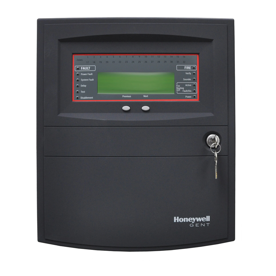
Fire 15:45 Fault Verify Heal thy Sounder Power Fault Vigilo n Fire System Fire Routing O/P System Fault GENT 2015 Pt 2 & 4 Design ed to EN54 Delay Operating instructions Power Test Next Previ ous Disablem ent Vigilon panel and Network node... -
Page 2: Table Of Contents
How to set the system clock ..............24 Contents How to use the integral printer ..............25 Preface ..................... 3 To Switch On / Off the Printer ..............25 Associated Documents ................3 To action a Paper Feed ................25 Conventions .................... -
Page 3: Preface
Vigilon fire alarm system Preface Symbol Keys This is the second issue of the operating instructions for the Vigilon panel based fi re detection and alarm system having the 2km loop cards. It covers Fire Alarm Routing Equipment and Fire Protection Equipment controls. What you will see. -
Page 4: User Responsibility
User responsibility Daily User responsibility BS 5839 : Part 1, states that the system should be inspected Your fi re alarm system should have been designed, installed daily to ensure: and commissioned to your site specifi c requirements and That a normal indication is given at the control and ... -
Page 5: Limitation Of False Alarm
Fire Fault 15:45 Verify Healthy Power Fault Sounder Vigilon Fire System Fire Routing O/P System Fault GENT 2015 Pt 2 & 4 Designed to EN54 Delay Power Test Previous Next Disablement Control panel (with zone indicators) Network node (has no zone indicators) -
Page 6: Network Node
Control and indicating equipment Network Node Zonal Mimic panels A Network node provides central indications of events in a There may also be a number of mimic and zonal mimic panels Vigilon network. installed in the protected premises, to provide visual indications in a graphical and zonal format. -
Page 7: Description Of Controls And Indications
# NOT USED on BS Vigilon panel Zones Fault Fire 15:45 Verify Power Fault System Fault Vigilon Fire System Sounder GENT 2015 Fire Routing O/P Delay Designed to EN54 Pt 2 & 4 Active Test Fault/Dis Disablement Previous Next Power... - Page 8 Description of controls and indications Indicators Description Display The Display provides messages of the system status / events by means of 8 lines by 40 characters per line display. Secret-until-lit fi re zone indicators. When the “Zones” text and number(s) are illuminated it indicates that a FIRE has Zones been detected in the indicated zone(s).
- Page 9 Vigilon fire alarm system Indicators Description When illuminated it indicates that one or more delay blocks are setup on the panel. Sounder (amber) When illuminated it indicates one or more zones are in Test mode. Test (amber) Controls Description Pressing the Menu On/Off will enable/disable the on screen menu facility, which gives access to the system menus. Menu On/Off The ‘Fn’...
- Page 10 Description of controls and indications Controls If the Verify facility has been set up, then pressing the Verify button in the event of a fi re condition, increases the Verify time delay before the sounders are activated. This gives the user time to investigate the cause of the alarm and the option of cancelling the alarm within the delay time period.
-
Page 11: Normal Condition
Fault 15:45 Verify Healthy Power Fault Sounder Vigilon Fire System Fire Routing O/P System Fault GENT 2015 Designed to EN54 Pt 2 & 4 Delay Power Test Next Previous Disablement written on the label that is fi tted on the back of the panel’s outer door. -
Page 12: Weekly Tests
Weekly tests Check the alarms are sounding in the building Weekly tests and an indication is given of the fi re event. Every week during normal working hours the fi re detection and alarm Turn the test key anticlockwise one quarter of ... -
Page 13: How To Manually Raise An Alarm Of Fire
Vigilon fire alarm system With the panel door open: How to manually raise an alarm of FIRE To cancel You can stop the panel buzzer from If you see a fi re in the protected premises and want to raise a fi re buzzer sounding. -
Page 14: Automatic Detection Of Fire
Automatic detection of FIRE With the panel door open: Automatic detection of FIRE To cancel You can stop the panel buzzer from A fi re in your protected premises is automatically sensed at any buzzer sounding. one of the fi re detection devices installed in the building, such as a sensor or a fi... - Page 15 Vigilon fire alarm system Multiple fi res Fire Previous Next Use the [Previous] or [Next] buttons or with the outer door open you can to scroll the fi re events. The 1st Fire will always appear at top of display. All subsequent fi res appear beneath the 1st Fire. The zonal indicators show zones in fi...
-
Page 16: Fault Conditions
Fault conditions With the panel door open: Fault conditions To cancel You can stop the panel buzzer from A fault in the system, such as failure of mains power to the panel or removal buzzer sounding. of any monitoring device will cause a Fault condition to appear at the Cancel buzzer control panel. -
Page 17: Typical Fault Messages
Vigilon fire alarm system Typical fault messages The table below shows some of the more typical fault messages and indications that may appear at the panel if there are faults in the system. It also gives the meaning and possible rectifi cation action for each fault. Flashing Message Indication... -
Page 18: Disablement Conditions
Disablement conditions Disablement conditions A disablement condition is the manual or automatic disablement of a part of the fi re detection system. An automatic disablement may be pre-confi gured for your premises to disable smoke sensors during the normal working hours in areas where smoke or dust may be present. -
Page 19: Typical Disablement Messages
Vigilon fire alarm system Typical Disablement Messages The following table shows some typical disablement messages and indications that may appear at the panel. Flashing Message Indication Meaning Action FARE Disabled The Fire Alarm Routing Equipment FARE has If manually disabled then investigate and Fault Fault/Dis been Disabled. -
Page 20: Menu Controls
User code is undesirable, Verify Power Fault Vigilon Fire System so it is recommended that a Sounder System Fault GENT 2015 Fire Routing O/P Designed to EN54 Pt 2 & 4 customer password is setup. Delay Active [Control] [ Set Up... -
Page 21: To Carry Out A Display Test
Vigilon fire alarm system To carry out a display test How to change your PIN code You can test the message display and the indicators on the The following terms: Password, PIN, Usercode and Access control panel. code mean the same and are used interchangeably. A Customer user PIN code (password) is normally set up by a. -
Page 22: How To View The Historic Events
How to view the historic events How to view the historic events Cards inside the control panel Up to 255 events are stored in the Historic log of the panel. To The control panel uses the following card reference numbers. view the Historic log. -
Page 23: How To Save Changes To Memory
Vigilon fire alarm system How to save changes to memory How to view active events If you make any changes to a Labels or Password then you An active event is an event that is still present and has not must save these to the NVM (Non Volatile Memory) or Memory cleared. -
Page 24: How To Set The System Clock
How to set the system clock Press the F2 or F3 key to [Retard] or [Advance] to the How to set the system clock desired setting. k. Press the F1 key to select [Next]. Check that the Year is An incorrect setting of the system clock will now fl... -
Page 25: How To Use The Integral Printer
Vigilon fire alarm system How to use the integral printer How to enable/disable Sensing Assuming the panel has an integral printer: These operations are not applicable for a Network Node. To Switch On / Off the Printer a. Press the MENU ON/OFF key. It is only possible to disable a Manual Call Point (MCP) individually, not as part of a range. -
Page 26: How To Enable/Disable A Zone
How to enable/disable a zone How to enable/disable a zone How to manually switch On / Off FARE The fi re alarm routing output via the FARE interface that These operations are not applicable for a Network Node. signals the Alarm Receiving Centre can be manually switched A zone is a subdivision of your premises that is protected On/Off. -
Page 27: How To Manually Disable / Enable Fare
Vigilon fire alarm system How to manually Disable / Enable FARE How to manually Disable / Enable FPE The FARE interface can be manually Enable or Disable to stop All the FPE interfaces in a system that signal to all fi re signal to Fire Alarm Routing Equipment and to prevent signal to protection equipment can be manually disabled or enabled. -
Page 28: How To Enable/Disable An Io Line
How to enable/disable an IO line How to enable/disable an IO line How to enable/disable auxiliary relay The control panel / network node has two These operations are not applicable for a Network Node. auxiliary relays that provides voltage free contacts to control external equipment in the event of a fi... -
Page 29: Other Enable/Disable Options
Vigilon fire alarm system Other enable/disable options How to view a device label There are other options such This operation is not applicable for a Network Node. as Sounders, Command Build, Each device in the system is given a location label at the time the system is Group, and Communication that commissioned to identify its installation position. -
Page 30: How To View A Zone Label
How to view a zone label How to view a zone label How to view a I/O line label This operation is not applicable for a Network Node. This operation is not applicable for a An interface unit can have up to four input/output (IO) lines. Each Network Node. -
Page 31: How To View The Local Panel Label
Vigilon fire alarm system How to view the local panel label To view or print a map When there is a network of control panels and nodes The [Loop map] option is not applicable for Network Node. connected together in a system then each panel/node is usually given an identifi... -
Page 32: Editing Labels
Editing labels Editing labels How to edit a device label This operation is not applicable for a Network Node. Any changes to labels There can be up to 200 devices connected to a loop, devices like fi re sensors must be backed up and manual call points. -
Page 33: How To Edit An Input/Output Line Label
Vigilon fire alarm system Press the F2 button to select [Enter]. Notice the How to edit an Input/output line label previous label appears on the display with a fl ashing This operation is not applicable for a Network Node. fi rst character to prompt you to edit a label. If there is Each input / output (IO) line of an interface unit can be given a no label then the line is blank. -
Page 34: How To Edit A Zone Label
How to edit a zone label How to edit a zone label How to edit a local panel label A label is normally given to the control panel to This operation is not applicable for a Network Node. identify its location in a network. A previously entered Each zone can be given a label and an entered label can be label can be modifi... -
Page 35: How To Edit Custom Label
Vigilon fire alarm system How to edit custom label A custom message or label is displayed beneath the Designed to EN54 Pt 2 & 4 line on the panel. The message or label can be up to 40 characters in length and it can be contact information of the person responsible for the fi re alarm system or it can have contact phone number of the servicing organisation. -
Page 36: Maintenance
Maintenance Maintenance Replacing the glass on a Manual Call Point a. Disengage the front cover from the call point assembly using the end of the test key. Insert the key into the slots ‘E’ on the underside of the call point to compress the retaining tabs and the from the bottom edge lift out the cover. -
Page 37: Battery Replacement
Vigilon fire alarm system Battery replacement It is recommended where batteries are installed they are replaced at Choose the paper roll feed appropriate for your panel 4 Yearly intervals from the date the system is fi rst commissioned. Door Paper Any servicing work on the system must be carried out roll by a suitably trained person, such as an engineer from... -
Page 38: Repair Function
Maintenance Repair function This operation is not applicable for a Network Node. Any wiring fault on the system must be rectifi ed by an engineer from the servicing organisation, for contact details see the log book. A wiring fault will require correction to the wiring before running a [Repair] command at the main panel. The repair function is accessible using customer (level 2) password, however under normal circumstances it is unnecessary to use this function. - Page 39 Vigilon fire alarm system This page has been intentionally left blank.
- Page 40 Gent by Honeywell reserves the right to revise this publication from time to time and make changes to the content hereof without obligation to notify any person of such revisions of changes. Hamilton Industrial Park, Waterside Road, Leicester LE5 1TN Website: www.gent.co.uk...