ABB ACS800 Series Hardware Manual
+c236 wind turbine convert for asynchronous slip ring generators
Hide thumbs
Also See for ACS800 Series:
- Firmware manual (340 pages) ,
- Hardware manual (210 pages) ,
- Cabinet installation and operating instruction (162 pages)

Related Manuals for ABB ACS800 Series


Summary of Contents for ABB ACS800 Series
- Page 1 ACS800 Hardware Manual ACS800-67 (+C236) Wind Turbine Convert for Asynchronous Slip Ring Generators...
- Page 2 You can find manuals and other product documents in PDF format on the Internet. See section Document library on the Internet on the inside of the back cover. For manuals not available in the Document library, contact your local ABB repre- sentative.
- Page 3 ACS800-67 (+C236) Wind Turbine Converters for Asynchronous Slip Ring Generators Hardware Manual 3AXD50000203802 EN Rev A EFFECTIVE: 2018-05-01 2018 ABB Beijing Drive Systems Co. Ltd. All Rights Reserved.
-
Page 5: Safety Instructions
Safety instructions Contents of this chapter This chapter contains safety instructions which you must obey when you install and operate the converter, and do maintenance on the converter. If you ignore the safety instructions, injury, death or damage can occur to the converter, the generator or other adjoining equipment. -
Page 6: Installation And Maintenance Work
Installation and maintenance work These warnings are intended for all who work on the converter, generator cable or generator. WARNING! • Only qualified electricians are allowed to install and maintain the converter. • Before any installation work, the stator of the generator and the supply line input of the ACS800-67 must be isolated from the supply grid. - Page 7 • Do not make any insulation tests without disconnecting the converter from the cabling first. • When joining shipping splits (if any), check the cable connections at the joints before switching on the supply voltage. • Live parts on the inside of the doors are protected against direct contact. Pay special attention when handling metallic shrouds.
- Page 8 WARNING! Ignoring the following instructions can cause physical injury or death, or damage to the equipment. • Use extreme caution when manoeuvring a converter or filter module that runs on wheels. The modules are heavy and have a high center of gravity. Make sure that the module does not topple over when you move it on the floor.
-
Page 9: Grounding
• Fastening the cabinet by riveting or welding is not recommended. However, if welding is necessary, ensure the return wire is properly connected in order not to damage the electronic equipment in the cabinet. Also ensure that welding fumes are not inhaled. •... -
Page 10: Fibre Optic Cables
Fibre optic cables WARNING! Obey these instructions. If you ignore them, equipment malfunction and damage to the fiber optic cables can occur. • Handle the fibre optic cables with care. When you unplug the cables, always hold the connector, not the cable itself. Do not touch the ends of the fibers with bare hands as the ends are extremely sensitive to dirt. -
Page 11: Table Of Contents
Table of contents Safety instructions Contents of this chapter ............5 Use of warnings and notes . - Page 12 NCAN-02C ..............34 NETA-21C+NEXA-21C .
- Page 13 Protection against short circuit inside the cabinet ........58 DC fuses .
- Page 14 Installation checklist Checklist ..............85 Start-up Contents of this chapter .
- Page 15 Providing feedback on ABB Drives manuals ........
- Page 16 Table of contents...
-
Page 17: About This Manual
About this manual Contents of this chapter This chapter describes the intended audience and contents of the manual. It contains a flowchart of steps in checking the delivery, installing and commissioning the converter. The flowchart refers to chapters/sections in this manual and other manuals. -
Page 18: Installation And Commissioning Flowchart
Technical data contains the technical specifications of the converter, e.g. ratings, frame sizes and technical requirements and provisions for fulfilling the requirements for CE and other markings. Installation and commissioning flowchart Task Plan the installation. Technical data Check the ambient conditions, ratings, required Planning the electrical installation cooling air flow, input power connection, compatibility Option manuals (if optional equipment is... -
Page 19: Terms And Abbreviations
Terms and abbreviations Term/Abbreviation Explanation BINT Main Circuit Interface Board Application and Motor Controller Board. Part of the NDCU Drive Control Unit ZPOW Power Supply Board Auxiliary control The cubicle with auxiliary devices such as auxiliary voltage circuit cubicle (ACU) breakers, control electronics, measurement boards, etc. - Page 20 Term/Abbreviation Explanation Radio Frequency Interference RMIO Motor Control and I/O Board. Part of the RDCU Drive Control Unit Rotor-side converter A converter that is connected to the generator rotor and controls its operation. Uninterruptible power supply About this manual...
-
Page 21: Hardware Description
ACS800-67 wind turbine converter is designed for use with induction generators with wound rotor and slip rings, such as the ABB AMK series. The converter is connected between the generator rotor and the supply network. The converter can be installed in the tower base or in the nacelle. -
Page 22: Grid-Side And Rotor-Side Converters
Line coupling Main circuit Medium voltage Stator contactor breaker transformer switchgear Brake MCB3 MCB1 Gear box MCB3 on/off control MCB emergency switch off control Rotor Wind turbine converter Doubly-fed ABRU generator MCB1 on/off control Pitch drive MCB2 Rotor bearing ACBU Converter control MCB control Wind turbine controller... -
Page 23: Voltage And Current Waveforms
The diagram below shows an example of a common DC bus converter system. In this example the converter consists of one grid-side converter, and two parallel connected rotor-side converters. Common Rotor-side converters Grid-side converter DC bus to grid to generator The wind turbine converter line current I consists of grid-side converter current line... -
Page 24: Distortion
Waveforms of ACS800-67 2000 1500 1000 -500 -1000 line -1500 -2000 Time (ms) Distortion IGBT-type grid-side converter unit does not generate characteristic current/voltage harmonics like a traditional 6- or 12-pulse bridge does, because of the sinusoidal waveform of the line current. Typical harmonic components of the voltage and current distortion are shown below. - Page 25 Harmonic distortion of current (%) THD 3 Harmonic order Hardware description...
-
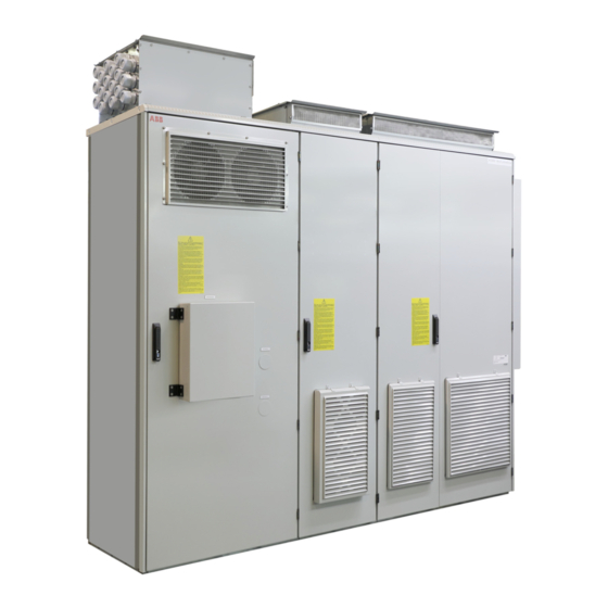
Page 26: Mechanical Construction
A typical spectrum of the current distortion is shown below. Each point is presented as a percentage of the fundamental current. Current spectrum of ACS800-67 (%) 0.01 0.001 1000 2000 3000 4000 5000 6000 7000 8000 9000 10000 Frequency (Hz) Mechanical construction Mechanically the power cabinet is an integrated part of the ACS800-67(+C236) converter. -
Page 27: Single Line Diagram
Single line diagram Hardware description... -
Page 28: Cabinet Layout
Cabinet layout Location of main components is shown in the picture below. See the circuit diagram for their electrical connections. 编号 描述 Stator contactor Main circuit breaker Cabinet heaters Grid-side (L1, L2, L3) cable lead-throughs Grid-side cable connection terminals Grid-side contactor and AC fuse Charging circuit lightning conductor Stator-side (U, V, W) cable lead-throughs... - Page 29 The converter is housed in a cabinet specially designed for wind turbine converters. An example layout of the converter is presented in the following drawings. F5.1-2 U11.1 U11.2 X01.1-4 F5.1-2 Converter DC Fuse LCL filter Grid-side converter Chopper X01.1-4 Power contactor U11.1-2 Rotor-side converter Hardware description...
- Page 30 Hardware description...
-
Page 31: Grid Supply And Stator Connections
Control frame Grid supply and stator connections Three phases of supply grid are connected to the bottom of grid supply section(L1/ L2/L3). Control power supply for converter section and for auxiliary supply is taken from bus bars below grid air circuit breaker with double feeding cables. Air circuit breaker Q101 is used to connect and disconnect both stator and converter to / from grid supply, stator contactor K102 is used to connect and disconnect the Hardware description... -
Page 32: Grid-Side Converter Supply
generator to / from the supply grid. Before connection, the converter performs network synchronization. In fault situations where the circuit breaker trips, the converter stops and the user has to manually reconnect the breaker. See the section Breaker settings. Generator stator connections are in power cabinet (U/V/W). Current transformers T109.1 and T109.2 are used to measure the stator current from two phases. -
Page 33: Functional Description
Functional description Devices on the ACU cabinet are listed below. Device Description K3.1 Cooling fan control of ACU cabinet. Grid MCB control. YC/YO changing, monitoring. Grid MCB status monitoring. Emergency switching-off of grid MCB, stator MCB and grid-side converter contactor. Common fault output. -
Page 34: Control Boards And Optional Modules
Device Description A411 NCAN module Grid-side current and voltage measuring unit CROWBAR, protection device of rotor-side Heater Control boards and optional modules RDCU-12C Grid-side converter is controlled by its own RDCU control unit (containing the RMIO- 12C board). The RDCU is connected to the grid-side converter modules by a fiber optic link. -
Page 35: Raio-01
also contains a data logger for collecting and storing real-time data from the module power stages to help fault tracing and analysis. RAIO-01 Analog Expansion Module (RAIO) is an extended module for the RMIO board. The inlet air temperature of ACU can be read through RAIO. Charging circuit Resistor R1, fuses F15 and contactor K2 form a part of the charging circuit located on the slide-out frame. - Page 36 Start-up order is: 1) Grid air-circuit breaker (MCB1), 2) Grid-side converter contactor (MCB2), 3) Stator air-circuit breaker/ contactor (MCB3) Shutdown order is reversed: 1) Stator air-circuit breaker/contactor (MCB3), 2) Grid-side converter contactor (MCB2), 3) Grid air-circuit breaker (MCB1) The conditions for closing grid air-circuit breaker (MCB1) are: Grid air-circuit breaker (MCB1) closing •...
- Page 37 Grid air-circuit breaker (MCB1) 2. Stator air-circuit breaker/contactor (MCB3) FAULT opening (emergency shutdown – In case the stator air-circuit breaker/contactor does not obey OPEN stator air-circuit breaker/contactor command from the converter, the monitoring circuit will find that stator (MCB3) fault) air-circuit breaker/contactor (MCB3) is still closed (K31 relay is ON) after the time delay of 2 sec.
- Page 38 Converter module layout is presented in the following drawing. A21-23 BGAD-21C/IGBT BINT-67C BGDR-01C B31-33 Current transducer ZPOW-7B1C Thermal Switch Hardware description...
-
Page 39: Modules
Modules The modules run on wheels, and can easily be removed from the cubicle for cable installation or service. Each module must be extracted from the cabinet for cabling and then re-inserted. The rotor/grid connection is via a quick connector at the back of the module that couples when the module is inserted into the cabinet. -
Page 40: Alcl Filter Module
ALCL filter module ALCL filters are used for minimising the emissions of the converter towards the grid. Item Explanation AC input busbars AC output terminals: Handles Hardware description... -
Page 41: Blcl Filter Module
BLCL filter module BLCL filters are used for minimising the emissions of the converter towards the grid. Item Explanation AC input busbars AC output terminals: Handles Hardware description... -
Page 42: Heating And Cooling
Heating and cooling Module and the LCL filter is equipped with a fan, which runs at constant speed. The cabinet has a heating system. See section Cooling and heating logic. Crowbar The crowbar circuit is used for overvoltage protection in abnormal grid conditions, e.g. -
Page 43: Crowbar Resistor
Crowbar resistor Du/dt filter Du/dt filters suppress voltage spikes and rapid voltage changes that stress the rotor insulation. Du/dt filters are included in the rotor-side converter modules. Control section All the control electronics are installed in a control frame in the auxiliary control cubicle, separate from other cubicles. -
Page 44: Interboard Connection Diagram
Interboard connection diagram The diagram below shows the principal interboard optical connections of the converter. For details, see the circuit diagrams delivered with the converter. Upper-level control system Electrical connections Electrical bus Nxxx Cabinet heating logic Fieldbus See section Cooling and DriveWare PC Tools heating logic below. -
Page 45: Cooling And Heating Logic
Cooling and heating logic The temperature and humidity must be within allowed limits in the cabinet before the converter can be powered up. The converter cabinet is equipped with a heating logic which controls the cabinet heating system, allowing the converter to start only when the operating conditions are met. - Page 46 ~ 230V Module Cabinet X104.1 BH002 BH001 X104.2 RH>80% T>10°C RH>80% BT001 K3.4 24VDC K3.1 T>55°C BT002 T>35°C ZV005_6 Heater K3.1 Heater U11.1 U11.2 >11 >11 >11 K3.4 ~3*400V Hardware description...
-
Page 47: Type Code
• The option codes follow the basic code. Each option code starts with an identifying letter (common for the whole product series), followed by descriptive digits. The option codes are separated by plus signs. The main selections are described below. For more information, contact your local ABB representative. Basic code Digit no. Name/Description... - Page 48 Hardware description...
-
Page 49: Mechanical Installation
Mechanical installation Contents of this chapter This chapter describes the mechanical installation procedure of the converter. General See chapter Technical data for allowable operating conditions and requirements for free space around the unit. The unit should be installed in an upright vertical position. The floor that the unit is installed on should be of non-flammable material, as smooth as possible, and strong enough to support the weight of the unit. -
Page 50: Moving The Unit
Moving the unit …by crane Use the steel lifting lugs attached to the top of the cabinet. Insert the lifting ropes or slings into the holes of the lifting lugs. The lifting lugs can be removed (not mandatory) once the cabinet is in its final position. If the lifting lugs are removed, the bolts must be refastened to retain the degree of protection of the cabinet. -
Page 51: On Rollers
…on rollers Remove the wooden bottom frame which is part of the shipment. Lay the unit on the rollers and move it carefully until close to its final location. Remove the rollers by lifting the unit with a crane, fork-lift, pallet truck or jack as described above. -
Page 52: Before Installation
Before installation Delivery check The converter delivery contains: • converter cabinet • optional modules (if ordered) installed into the control frame at the factory • ramp for extracting modules from the cabinet • hardware manual • appropriate firmware manuals and guides •... -
Page 53: Installation Procedure
Installation procedure (1) The cabinet can be installed with its back against a wall. Fasten the unit (or first shipping split) to the floor with fastening clamps or through the holes inside the cabinet. For the location of the fastening holes, see delivery specific dimensional drawings. -
Page 54: Miscellaneous
Miscellaneous Cable conduit in the floor below the cabinet A cable conduit can be constructed below the 400 mm (15.7 in.) wide middle part of the cabinet. The cabinet weight lies on the two 100 mm (3.9 in.) wide transverse sections which the floor must carry. -
Page 55: Electric Welding
Electric welding It is not recommended to fasten the cabinet by welding. However, if welding is necessary, follow the instructions below. Cabinets without flat bars at the base • Connect the return conductor of the welding equipment to the cabinet frame at the bottom within 0.5 metres of the welding point. - Page 56 Mechanical installation...
-
Page 57: Planning The Electrical Installation
To avoid damage to generator bearings, insulated N-end (non-driven end) bearings and output filters from ABB must be used. In addition, the cables must be selected and installed according to the instructions given in this manual. These types of filters are included in the ACS800-67 converter as default: •... -
Page 58: Grid Connection
Grid connection Disconnecting device (disconnecting means) The converter must be equipped with a hand operated input disconnecting device (disconnecting means) which isolates the converter and the generator from the supply grid. A switch fuse disconnector is available as option. The disconnecting device does not, however, isolate the input busbars from the supply grid. -
Page 59: Dc Fuses
cable. In case the 0.5 seconds operating time is exceeded with gG fuses, ultrarapid (aR) fuses will in most cases reduce the operating time to an acceptable level. WARNING! Circuit breakers are not capable of providing sufficient protection because they are inherently slower than fuses. Always use fuses with circuit breakers. -
Page 60: Restarting After An Emergency Stop
Restarting after an emergency stop After an emergency stop, the emergency stop button must be released and a reset performed before the main contactor (or air circuit breaker and stator contactor) can be closed and the converter started. Selecting the power cables This section contains the general cable selection rules. - Page 61 Recommended A separate PE conductor is required if the conductivity Symmetrical shielded cable: three phase conductors of the cable shield is <50% of the conductivity of the and a concentric or otherwise symmetrically phase conductor. constructed PE conductor, and a shield PE conductor Shield Shield...
-
Page 62: Supply Line Cable Connection For Low Power Supply
Note: The N conductor is not normally used with ACS800-67 converters although it is visible in the following diagrams. Supply line cable connection for low power supply A low current (< 300 A) single cable connection is represented below. Line coupling Converter transformer 1) As short as possible for... -
Page 63: Cable Bus System
Cable bus system The connection of a high current (> 300 A) cable bus system that consists of several cables is represented below. In this system, less conductor material is needed due to better cooling of separate conductors. Line coupling Converter transformer L3 L2... -
Page 64: Rotor Cable Connection
Rotor cable connection Rotor cable connections for different cable types are represented below. For minimum radio frequency interference (RFI) at the generator end, earth the cable screen 360 degrees at the lead through or earth the cable by twisting the screen (flattened width >... -
Page 65: Conduit
Conduit Where conduits must be coupled together, bridge the joint with a ground conductor bonded to the conduit on each side of the joint. Bond the conduits also to the converter enclosure. Use separate conduits for input power, generator, brake resistors, and control wiring. - Page 66 WARNING! Never connect the supply power to the converter output terminals U2, V2 and W2. If frequent bypassing is required, employ mechanically connected switches or contactors. Mains (line) voltage applied to the output can result in permanent damage to the unit. Planning the electrical installation...
-
Page 67: Relay Output Contacts And Inductive Loads
Relay output contacts and inductive loads Inductive loads (such as relays, contactors, generators) cause voltage transients when switched off. The relay contacts of the RMIO board are protected with varistors against overvoltage peaks. In spite of this, it is highly recommended to equip inductive loads with noise attenuating circuits (varistors, RC filters [AC] or diodes [DC]) in order to minimize the EMC emission at switch off. -
Page 68: Selecting The Control Cables
Never mix 24 VDC and 115/230 VAC signals in the same cable. Relay cable The cable type with braided metallic screen (e.g. ÖLFLEX LAPPKABEL, Germany) has been tested and approved by ABB. Coaxial cable (for use with Advant Controllers AC 80 / AC 800M) • 75 ohm •... -
Page 69: Connection Of A Generator Temperature Sensor To The Converter I/O
Connection of a generator temperature sensor to the converter I/O WARNING! IEC 60664 requires double or reinforced insulation between live parts and the surface of accessible parts of electrical equipment which are either non-conductive or conductive but not connected to the protective earth. To fulfil this requirement, the connection of a thermistor (and other similar components) to the digital inputs of the converter can be implemented in three alternate ways:... -
Page 70: Control Cable Ducts
Control cable ducts 24 V 230 V 24 V 230 V Lead 24 V and 230 V control Not allowed unless the 24 V cables in separate ducts inside cable is insulated for 230 V or the cabinet. insulated with an insulation sleeving for 230 V. -
Page 71: Electrical Installation
Electrical installation Contents of this chapter This chapter describes the electrical installation procedure of the ACS800-67. WARNING! Only qualified electricians are allowed to carry out the work described in this chapter. Follow the Safety instructions on the first pages of this manual. Ignoring the safety instructions can cause injury or death. -
Page 72: Checking The Insulation Of The Assembly
Checking the insulation of the assembly Every converter has been tested for insulation between the main circuit and the chassis (2500 V rms 50 Hz for 1 second) at the factory. When checking the insulation of the assembly, proceed in the following manner. WARNING! Check the insulation before connecting the converter to the power supply network. -
Page 73: Dc And Ac Busbars
DC and AC busbars • Short circuit the L-shaped DC busbars of the converter modules. • Short circuit the L-shaped AC busbars of the LCL filter module. DC busbars AC busbars • Measure the insulation resistances between the DC busbars and the converter frame and between the AC busbars and the converter frame by using a measuring voltage of 1 kV DC. -
Page 74: Grid And Rotor Connections
Grid and rotor connections Connection diagram The diagram presents an example of the main connection diagram. *The switch fuse disconnector is not always included in the delivery! Power cabinet Converter Electrical installation... -
Page 75: Grid Supply Connection
Grid supply connection • Remove the protective cover. Connect the grid cables to grid terminals L1, L2 and L3. See the chapter Technical data. • Tighten the cable lead-through grommets and seal them properly. • Assemble the cooling fan and protective covers. Close the door. The recommended cable types are given in the chapter Planning the electrical installation. - Page 76 Quick connector U2, V2, W2 = Output busbars Rotor cabling example Electrical installation...
- Page 77 All rotor-side converter modules (two are shown below) are to be connected in parallel. It is recommended that the cabling from all rotor-side converter modules to the rotor is physically identical considering cable type, cross-sectional area, and length. Jumpering the output cables from one rotor-side converter to another (and then to the rotor) is also possible, but not recommended.
-
Page 78: Connection Procedure
Connection procedure WARNING! Use extreme caution when manoeuvring a converter or filter module that runs on wheels. The modules are heavy and have a high centre of gravity. They topple over easily if handled carelessly. Extract each module from the cabinet as follows: (1) Open the cabinet doors. - Page 79 (9) Extend the support legs of the module. Keep the legs extended until the module is about to be inserted back into the cabinet. LCL filter module: (10) Disconnect the L-shaped AC busbars on top of the filter module: Loosen the three upper screws (10a), but leave them in place.
-
Page 80: Control Connections
Cut the cables to suitable length. Strip the cables and conductors. Twist the cable screens into bundles and connect to cabinet PE (ground) busbar. Connect any separate ground conductors/cables to cabinet PE (ground) busbar. Connect the phase conductors to the output (U2, V2, W2) and input (L1, L2, L3) terminals. See section Cable terminals in chapter Technical data. -
Page 81: Control Unit Ndcu-33Cx/Rdcu-12C
Control unit NDCU-33Cx/RDCU-12C The connectors of the rotor-side converter control unit NDCU-33Cx (consisting of the NIOC-02C and AM33C boards) and the grid-side converter control unit RDCU-12C (containing the RMIO-12C board) are presented below. For further information on the RDCU control unit, see RDCU-02(C) Drive Control Unit Hardware Manual [3AFE64636324 [English)]. -
Page 82: Voltage And Current Measurement Unit Nuim-61C
Voltage and Current Measurement Unit NUIM-61C The connectors of the Voltage and Current Measurement Unit NUIM-61C are presented below. See ACS800-67(LC) Doubly-fed Induction Generator Control Program Firmware Manual [3AUA0000071689 (English)] for more information. Signal connection between auxiliary power supply and main control system of the fan Terminal block The connecting terminal block between auxiliary power supply and the main control... - Page 83 Termin Signal Description al No. 1X7.2 PS:1 Encoder signal Encoder+24V PS:2 Encoder+24V Earth Encoder Z+ Encoder Z- Encoder A+ Encoder A- Encoder B+ Encoder B- Connecting shield 1X7.3 Fieldbus interface CANOPEN:H CANOPEN:L CANOPEN:GND PE(Shield) 1X7.3 Ethernet interface Net port 1X100 Reset signal Reset button...
- Page 84 Electrical installation...
-
Page 85: Installation Checklist
Installation checklist Checklist Check the mechanical and electrical installation of the converter before start-up. Go through the checklist below together with another person. MECHANICAL INSTALLATION: Check that… there is sufficient free space around the unit. See chapter Technical data: Free space requirements. - Page 86 there is no condensed humidity or ice anywhere on or inside the unit. If condensed humidity or ice is detected, use external heaters for evaporation. the L-shaped DC busbar connections (of the converter modules) and their tightening torques are OK. there is enough space between the two lower screws and bolts of the L-shaped DC busbars (of the converter modules) and the module frame.
-
Page 87: Start-Up
Start-up Contents of this chapter This chapter describes the start-up procedure of the converter. The installation of the converter system must be checked before start-up. See chapter Installation checklist. Start-up procedure Action Additional information WARNING! The work described in this chapter must only be carried out by a qualified electrician. The Safety instructions on the first pages of this manual must be followed. -
Page 88: Connecting Voltage To Grid Terminals And Auxiliary Circuit
Action Additional information Write down the following data on the converter system for later use. Note down any deviations from delivery documents. • Generator, pulse encoder and cooling fan rating plate data • Maximum and minimum speeds • Speed scaling factor, gear ratio, etc. •... -
Page 89: Control Program Set-Up
Action Additional information If the converter is equipped with an input fuse cubicle (optional), close Optional devices. See the circuit the fuse switches. diagrams delivered with the converter. Close the grid-side converter (rectifier) switch disconnector. On units with line contactors, the grid-side converter charges the contactor control capacitors (3 s at first start). - Page 90 Start-up...
-
Page 91: Maintenance
Maintenance Contents of this chapter This chapter contains a table of maintenance intervals, maintenance instructions, and the descriptions of LEDs. Safety instructions Only a qualified electrician is allowed to perform the maintenance. Before starting work inside the converter system, • isolate the generator stator and the input of the ACS800-67 from the grid. It is also highly recommended that the rotor of the generator is locked with a mechanical brake •... -
Page 92: Maintenance Intervals
Maintenance intervals If installed in an appropriate environment, the converter requires very little maintenance. This table lists the routine maintenance intervals recommended by ABB. Interval Maintenance action Instruction 3 months after commissioning and Tighten and clean the power every 3 years thereafter connections. -
Page 93: Rear Ventilation Filters
• Check the cleanliness of the cabinet. Clean the interior of the cabinet if necessary using a soft brush and a vacuum cleaner. • Close the door. Rear ventilation filters • Read and repeat the steps in Safety instructions above. •... -
Page 94: Power Connections
The cooling fan lifespan depends on the running time of the fan, ambient temperature and dust concentration. Each module has its own cooling fan. Replacements are available from ABB. Do not use other than ABB specified spare parts. The control program keeps track of the running time of the cooling fan of the grid-side converter modules. -
Page 95: Converter Module Fan Replacement
Converter module fan replacement 1. Read and repeat the steps in Safety instructions above. 2. Open the cabinet doors. 3. Remove the front shroud. 4. Remove tightening screws, and disconnect the fan wiring plug. 5. Remove the fan tightening screws and fan shroud. 6. -
Page 96: Frame R8I - Circuit Board Compartment Fan
Frame R8i – Circuit board compartment fan The R8i module is equipped with a fan blowing air through the circuit board compartment. The fan is accessible from the front of the module. WARNING! Repeat the steps described in section Safety instructions. - Page 97 6. Remove the fan from the fan holder. 7. Put the fan onto the threaded studs on the fan holder with the airflow direction arrow pointing towards the fan holder. 8. Install and tighten the four nuts removed earlier. 9. Connect the fan cable. 10.
-
Page 98: Power Cabinet Cooling Fan Replacement
11. Install and tighten the two M4×12 (T20) screws. Power cabinet cooling fan replacement 1. Read and repeat the steps in Safety instructions above. 2. Open the cabinet doors of stator part. 3. Disconnect the fan wiring plug. 4. Remove four screws. 5. -
Page 99: Blcl Filter Fan Replacement
4. Remove the locking screw (2). 5. Pull the fan out along its sliding rails (3). 6. Install a new fan in reverse order. BLCL filter fan replacement 1. Read and repeat the steps in Safety instructions above. 2. Open the cabinet doors. 3. -
Page 100: Heating Heater Replacement
Heating heater replacement 1. Read and repeat the steps in Safety instructions above. 2. Heating heater shall be changed as one unit. No attempt shall be made to disassemble the heater. 3. Open the power cabinet doors. 4. Below is an example of heater replacement. Remove the lower protective cover from stator section. -
Page 101: Heatsinks
Capacitor life can be prolonged by lowering the ambient temperature. It is not possible to predict capacitor failure. Capacitor failure is usually followed by damage to the unit and an input cable fuse failure, or a fault trip. Contact ABB if capacitor failure is suspected. - Page 102 ZPOW-7B1C Green The 24 V output voltage is ON. AMC-33** Internal fault: LED is on during program boot. Green Not in use with the current software version R P T2 S1S0 Green RESET signal is ON. Green Auxiliary voltage is OK. F M T1S3S2 T1...T2 Yellow...
-
Page 103: Technical Data
Technical data Contents of this chapter This chapter contains the technical specifications of the converter, e.g. ratings, frame sizes and technical requirements, and provisions for fulfilling the requirements for CE and other markings. Converter and filter module types The ACS800-67 wind turbine converter types are listed in the following table. ACS800-67 Grid-side converter Rotor-side converter... -
Page 104: Symbols
At altitudes from 2000 to 4000 m (6600 to 13123 ft) above sea level, the derating is 1% for every 100 m (328 ft). For a more accurate derating, use the DriveSize PC tool. If the installation site is higher than 2000 m (6600 ft) above sea level, please contact your local ABB representative or office for further information. -
Page 105: Ac Fuses
AC fuses The converter is equipped with AC fuses. Suitable Bussmann types are listed below. Equivalent fuses from other manufacturers can also be used. ACS800-67… AC Fuses (aR) Type Fuse size ABB code = 690 V 2200 170M6458 Size3 3ABD00036577 2500... -
Page 106: Breaker Settings
Breaker settings It is important that the grid supply breaker is typically set as indicated in the table below as all the components are dimensioned according to the limit. The breaker setting for all units has been set at the factory. There is no need to adjust the settings except when replacing breaker. -
Page 107: Cable Terminals
Cable terminals DC input and generator cable terminal sizes and tightening torques are given below. The terminals must be suitable for tin-plated busbars. Cable terminals Screw size Tightening torque DC terminals 50 N·m (37 lbf·ft) Max. intrusion into module: 20 mm (0.8 in.) Grid, stator and rotor 70 N·m (52 lbf·ft) terminals... -
Page 108: Ambient Conditions
IEC 62635 guidelines. To aid recycling, plastic parts are marked with an appropriate identification code. Please contact your local ABB distributor for further information on environmental aspects and recycling instructions for professional recyclers. End of life treatment must follow international and local regulations. -
Page 109: Compliance With The Machinery Directive
Top: 600 mm (23.5 in.) above the basic roof level of the cabinet. Compliance with the Machinery Directive The wind turbine converter complies with the European Union Machinery Directive requirements for a partly completed machinery. The declaration of incorporation is available from ABB. Technical data... - Page 110 Technical data...
-
Page 111: Further Information
Product and service inquiries Address any inquiries about the product to your local ABB representative, quoting the type designation and serial number of the unit in question. A listing of ABB sales, support and service contacts can be found by navigating to www.abb.com/searchchannels. - Page 112 Contact us www.abb.com/drives www.abb.com/drivespartners 3AXD50000203802 Rev A (EN) 2018-05-01...