Honeywell X Series User Manual
Show thumbs
Also See for X Series:
- Installation instruction sheet (11 pages) ,
- Installation instruction (5 pages) ,
- Manual (8 pages)
1
2
3
4
5
6
7
8
9
10
11
12
13
14
15
16
17
18
19
20
21
22
23
24
25
26
27
28
29
30
31
32
33
34
35
36
37
38
39
40
41
42
43
44
45
46
47
48
49
50
51
52
53
54
55
56
57
58
59
60
61
62
63
64
65
66
67
68
69
70
71
72
73
74
75
76
77
78
79
80
81
82
83
84
85
86
87
88
89
90
91
92
93
94
95
96
97
98
99
100
101
102
103
104
105
106
107
108
109
110
111
112
113
114
115
116
117
118
119
120
121
122
123
124
125
126
127
128
129
130
131
132
133
134
135
136
137
138
139
140
141
142
143
144
145
146
147
148
149
150
151
152
153
154
155
156
157
158
159
160
161
162
163
164
165
166
167
168
169
170
171
172
173
174
175
176
177
178
179
180
181
182
183
184
185
186
187
188
189
190
191
192
193
194
195
196
197
198
199
200
201
202
203
204
205
206
207
208
209
210
211
212
213
214
215
216
217
218
219
220
221
222
223
224
225
226
227
228
229
230
231
232
233
234
235
236
237
238
239
240
241
242
243
244
245
246
247
248
249
250
251
252
253
254
255
256
257
258
259
260
261
262
263
264
265
266
267
268
269
270
271
272
273
274
275
276
277
278
279
280
281
282
283
284
285
286
287
288
289
290
291
292
293
294
295
296
297
298
299
300
301
302
303
304
305
306
307
308
309
310
311
312
313
314
315
316
317
318
319
320
321
322
323
324
Table Of Contents
325

Related Manuals for Honeywell X Series


Summary of Contents for Honeywell X Series
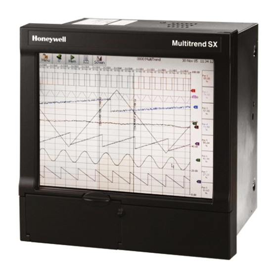
- Page 1 Minitrend QX, Multitrend SX and eZtrend QXe Recorders See, Store and Send Data Securely For the best in data acquisition, data security and peace of mind .. choose...
-
Page 2: User Manual
User manual 43-TV-25-30 Iss.6 GLO Aug 07 UK... -
Page 3: Table Of Contents
Table of Contents Section 1: Preface ................1 Preface ......................1 Thank you for choosing a Honeywell X Series recorder .......... 1 Documentation......................1 Notes ......................... 1 Trademarks ....................... 1 Safety ......................2 Symbols........................2 Static Electricity......................3 Protocols used in this manual ................ -
Page 4: Table Of Contents
Table of Contents Section 4: Recorder Setup ................45 Power up .......................45 1. Menu Access ....................... 45 2. Log On/Off ......................46 4. Time and Date Settings ..................47 5. Firmware Options ....................47 Menu Path....................... 47 Help......................... 48 Configure Menu ...................... 49 Setup Menu ...................... -
Page 5: Table Of Contents
Table of Contents Section 8: Communication ................205 Comms Configuration ................205 Standard Communication Interfaces ............205 Protocols....................... 206 Hardware Installation ................. 207 Getting connected - IP Address ................208 Local Area Network setup ..................209 Links to Remote Networks ..................209 Data Logging and Transfer .................. -
Page 6: Table Of Contents
Table of Contents Appendix A: Quality and Safety ..............269 CE Mark .....................269 Safety ......................269 Appendix B: Maths Expressions ..............271 Full Maths & Script Processing ..............271 Maths Credit Options .................... 271 Maths Variable and Function Tables..............272 Full Maths ......................279 Script Function Application Examples.............. -
Page 7: Section 1: Preface
Section 1: Preface Preface Thank you for choosing a Honeywell X Series recorder Thank you for purchasing the newest in our range of electronic data recording for Honey- well X Series Advanced Graphic Recorders. The Minitrend QX, Multitrend SX and eZtrend QXe paperless chart recorders are the latest development of the solid-state replacement for traditional paper recorders. -
Page 8: Safety
Safety The X Series range of instruments is compliant with the requirements of BS EN 61010- 1:2001 “Safety Requirements for Electrical Equipment for Measurement, Control and Labo- ratory Use” and UL 61010C-1 and CSA 22.2-1010.1, as options. If the equipment is used in a manner not specified, the protection provided by the equipment may be impaired. -
Page 9: Static Electricity
Static Electricity All circuit boards and electronic modules associated with this recorder contain components which are susceptible to damage caused by electrostatic discharge. Should it be necessary to handle such components, appropriate precautions in accordance with ANSI/ESD S20.20 Electrostatic Discharge Control Program Standard, should be observed. Protocols used in this manual Safety and Symbol Identification Table 1.3 :... -
Page 10: Hazardous Voltage
• A separable plug, without a locking device, to mate with a socket outlet in the building. 2. Whenever it is likely that protection has been impaired, the recorder should be made inoperative and secured against operation. The manufacturer's service centre should be contacted. -
Page 11: Section 2: Installation
Contents Check that the contents and accessories are correct against the order or Model Selection Guide using the model number on the recorder. Contact your authorised Honeywell dis- tributor or Honeywell immediately should there be any query. The contents are based on Unit Model Number ordered and will vary from unit to unit. The following list is provided as a general guide and not specific to any single unit. -
Page 12: Mechanical Installation
NOTICE The eZtrend QXe recorder is an Emissions Class A product. In a domestic environ- ment this product may cause radio interference in which case the user may be required to take adequate measures. Mechanical Installation Mounting and Viewing Angles Mounting - The Minitrend QX, Multitrend SX and eZtrend QXe recorders have an un- limited mounting angle. - Page 13 Panel cut-out size for the Multitrend SX recorder 281.00 (11.06”) Panel Panel 281.00 Cut-out Cut-out (11.06”) >20.00 >20.00 (0.787”) (0.787”) Panel Cut-out Please note the recommended spacing for adjacent mounting Multitrend SX Figure 2.2 Panel cut-out The Minitrend QX, Multitrend SX and eZtrend QXe recorders are DIN Standard sizes and should be panel mounted.
- Page 14 Minitrend QX Dimension details 4 Mounting clamp positions. For standard units fit only two brackets on opposite sides of the unit, either top and bottom or left and right slots. NEMA 4X rated recorders require all four mounting brackets to be fitted. Minitrend QX Figure 2.3 Recorder dimensions...
-
Page 15: Installation Instructions
Multitrend SX Dimension details 4 Mounting clamp positions. For standard units fit only two brackets on opposite sides of the unit, either top and bottom or left and right slots. NEMA 4X rated re- corders require all four mounting brackets to be fitted. Multitrend SX Figure 2.4 recorder dimensions... - Page 16 eZtrend QXe Dimension details 4 Mounting clamp positions. For standard units fit only two brackets on opposite sides of the unit, either top and bottom or left and right slots. NEMA 4X rated recorders require all four mounting brackets to be fitted. eZtrend QXe Figure 2.5 recorder dimensions...
- Page 17 Panel Mounting Clamp Installation The Minitrend QX, Multitrend SX and the eZtrend QXe recorders slide into the panel cut-out and are held in place by two (or four) panel clamps. The panel clamps should be fit- ted on diagonally opposite sides of the unit and tightened against the rear of the panel using two fixing screws.
- Page 18 Mounting Clamp Diagram Figure 2.1 Minitrend QX and eZtrend QXe Mounting clamp 2 mounting clamp positions required on two opposite sides of the recorder. Nema 4X requires all 4 clamps to be fitted. Mounting clamp slots Figure 2.2 Multitrend SX Mounting clamp 4 mounting clamp positions (2 shown).
-
Page 19: Electrical Installation
Replacement of fuses should be carried out by qualified service personnel. If the fuse should blow again there is probably a problem elsewhere within the unit and the recorder should be returned for inspection to your authorised Honeywell distributor or Honeywell Service department. Cables To fully comply with the requirements of the CE Mark, all cables connected to the rear of the unit should use screened cable terminated at both ends. - Page 20 CAUTION UNIT DAMAGE CONTROL To protect against component failures the user should fit an external fuse for the DC input power supply. The value should be 4A, time delay, high breaking capacity, mini- mum 60Vdc.rated. Failure to comply with these instructions may result in product damage WARNING HAZARDOUS VOLTAGES When using the recorder as portable equipment the optional rear cover must be fitted...
- Page 21 AC supply 100 - 250 VAC Earth screw Analogue Input/ (ground) Analogue Output/ or Pulse Input Slot A 24V DC/AC Input Slot B Slot C SPNC Slot D Relay Slot E Slot F 24V TX Power Supply Alarm Relay Output Digital I/O Slot G CJC Sensor...
-
Page 22: Analogue Input Card
20 to 30VDC / 20 to 25VAC Input Wire seal provision Instrument power (option) Earth screw (ground) AC supply 100 - 250 VAC Analogue Input card (option) Slot B CJC Sensor Alarm Relay or Digital I/O 24Vdc TX Slot G (option) 24V TX Power RS485 Supply Output /... - Page 23 WARNING HAZARDOUS VOLTAGES Insulation from channel to channel: Normally a channel can be safely connected to a hazardous voltage up to 300V AC common mode* with respect to earth. However, where a channel is connected to a safety low voltage circuit, an immediately adjacent channel must be adequately insulated from hazardous voltages between 150V AC and 300V AC max.
- Page 24 Thermocouples Ensure polarity of thermocouple is correct. Resistance Thermometers If using 2 wire R/T the + and - terminals must be linked together. See Figure 2.7 on page 19. Analogue Input Signal Wiring CAUTION CONTROL UNIT DAMAGE Do not apply a hazardous live voltage between + and - pins within a channel. (eg. 60V maximum on voltage ranges, 5V maximum on millivolts ranges).
-
Page 25: Qxe Analogue Input (Standard) Card
Figure 2.7 Input signal wiring Passive Burnout Active Burnout Current Thermocouples Thermocouples Volts/mV Ohms 2-wire R/T 4-wire R/T 3-wire R/T +ve optional connection Recorder setup will be required if wiring changes are made for Active Burnout Thermocou- ples. See “*Thermocouple Wiring Changes.” on page 57. Thermocouple Active Burnout status can be viewed in the Main Menu >... - Page 26 eZtrend QXe Figure 2.8 Analogue Input card (std) - Slot A 1 2 3 4 5 6 7 8 9 10 11 12 13 14 15 16 17 18 CH.1 CH.2 CH.3 CH.4 CH.5 CH.6 WARNING HAZARDOUS VOLTAGES Insulation from channel to channel: Normally a channel can be safely connected to a hazardous voltage up to 150V AC common mode* with respect to earth.
-
Page 27: Analogue Output Card
CAUTION CONTROL UNIT DAMAGE Do not apply a hazardous live voltage between + and - pins within a channel (e.g. 60V maximum on voltage ranges, 5V maximum on millivolts ranges). The * pin should be connected only as part of ohms or R/T measurements. Ohms and R/T measurements share a common connection (* pin) with all channels in the same bank (the inputs are divided into two banks: inputs 1 to 3 are one bank, and inputs 4 to 6, if fitted, are another bank). -
Page 28: Pulse Input Card
Analogue Output Channel Numbers The Analogue Output cards are either 2 or 4 channels using a connector that only takes up half the length of the connector slot. Looking from the rear of the unit the Analogue Out con- nector is on the left of the Analogue slot with a blanking plate on the right. Table 2.4 : Analogue Output card Slot B... - Page 29 WARNING HAZARDOUS VOLTAGES Insulation from channel to channel: Normally a channel can be safely connected to a hazardous voltage up to 300V AC common mode* with respect to earth. However, where a channel is connected to a safety low voltage circuit, an immediately adjacent channel must be adequately insulated from hazardous voltages between 150V AC and 300V AC max.
-
Page 30: Transmitter Power Supply Card
Transmitter Power Supply Card The Minitrend QX option is Transmitter power supply 24V DC 200 mA and is fitted to the power supply card within the unit. Connection is made via a 2-way connector at the rear of the unit, the mating half is supplied with this option. - Page 31 The Minitrend QX and the eZtrend QXe recorders have only one slot available for digital inputs and relay outputs for either a 4 or 8 channel Alarm Relay card or an 8 or 16 channel Digital I/O card fitted in slot G, the position is identified on the rear panel. The 16 channel Digital I/O card is not available on the eZtrend QXe recorders.
- Page 32 Alarm Relay Channel Numbers The Alarm Relay cards are either 4 or 8 channels with a full length connector taking up 8 channels even though the cards only operate on 4 channels or 8 channels. The 8 channels Alarm Relay card has 2 digital inputs available on the last 2 channels. There are no Digital Inputs available on the 4 channels Alarm Relay card.
- Page 33 NOTICE For Digital Inputs, short together the 2 pins of the channels with a switch or a relay. Pulse Inputs The 8 and 16 Digital I/O option card has 4 channels that can be set as pulse inputs (first 4 channels).
-
Page 34: Communications Connections
Communications Connections Ethernet The Ethernet port is fitted to all X Series recorders as standard and uses a standard RJ45 Ethernet connection. After connection, select the Ethernet port from the Comms menu and select the required protocol from the Protocol menu eg.Modbus. -
Page 35: Eztrend Qxe Expansion Card
RS485 Minitrend QX and Multitrend SX recorders. The RS485 port is fitted as standard as a part of the processor card and uses a 3-way connection. After connection, select the RS485 port from the Comms menu and select the required protocol from the Protocol menu +A -B GND eg. - Page 36 Keyboards All keyboards are native USB keyboards. Local keyboard layouts are not supported; all key- boards are recognised as US layout (QWERTY). Cordless keyboards and mice are not supported: • Dell Model # SK-8115 Keyboard • IBM ACC42 with USB hubs •...
-
Page 37: Section 3: Overview
Section 3: Overview Functions and Features Up to 16 Analogue Inputs Data Storage media: QX - Up to 192 “soft alarms” - for the Minitrend QX, 48 6 per pen • QX/SX Compact Flash - up for the Multitrend SX and SX - Up to 576 “soft alarms”... - Page 38 Comprehensive Connectivity • 10/100 Ethernet (DHCP), Web, OPC Server and E-mail Trend Server Pro • FTP and TCP/IP transfer of encrypted data by using software. • RS485 Modbus Protocol (A Comms option card and expansion card are required for the eZtrend QXe recorder).
- Page 39 • Counters • Modbus master communications • Alert System • Sound system - add sound effects to identify occurrences • Email facility - the recorder will email an event notification and include a screen shot of the occurrence as an attachment. 43-TV-25-30 Iss.6 GLO Aug 07 UK...
-
Page 40: Recorder Functionality
Recorder Functionality • X Series recorders provide flexible electronic data acquisition and recording in a high func- tionality instrument. Minitrend QX is a DIN standard 144mm format recorder with a 5.5” QVGA display and the Multitrend SX is a large 12.1” diagonal display format recorder. The eZtrend QXe is a DIN standard 144mm format recorder with a 5”... -
Page 41: Features
Features Display Minitrend QX • 5.5” Colour Active TFT for the and 12.1” Colour Active TFT for the Multitrend SX and 5” Colour Active TFT for the eZtrend QXe - with more than 256,000 colours makes it easy to interpret process data and take action with the intuitive bar charts, digital values, trends or customised displays. - Page 42 Data Export - Removable compact flash and USB flash storage device provides multiple data storage alternatives. Data is stored in a secure binary encrypted format, with the recorder’s configurations, pro- viding added security of the data files. (Compact Flash is not available for the eZtrend QXerecorder). Removable Compact flash and USB flash storage devices External USB Devices...
- Page 43 Batch The Batch function allows the user to segment portions of data for further analysis. Batch enhances the management of data collected in a non-continuous process, known as batch processing, used in thermal treatment, sterilisation, food processing and chemical reactions. Concurrent batch mode is now available where each batch is associated to a group of pens.
-
Page 44: Options - Hardware
• Security tag - “wire seal provision” provides added security to seal the front door and rear when using optional rear cover to prevent undetected entry to these areas of the recorder. • USB Ports - Front and rear USB host ports for data and setup transfers or remote screen through these ports. - Page 45 Multitrend SX Standard Screens The Multitrend SX recorder has up to 20 screens available for displaying combinations of charts, bars and DPMs can be configured, 4 examples below. Horizontal Chart, 8 Vertical Bars & 8 DPMS 16 Digital Panel Meters showing Max/Min values and Totals for each pen 16 Horizontal Bars...
- Page 46 Minitrend QX Standard Screens The Minitrend QX recorder has up to 12 screens available for displaying combinations of charts, bars and DPMs can be configured, 6 examples below. Horizontal Chart and DPMs Horizontal Chart, 4 Vertical Bars and 4 DPMs 8 Digital Panel Meters 8 Horizontal Bars DPMs and Scales...
- Page 47 eZtrend QXe Standard Screens The eZtrend QXe recorder has up to 10 screens available for displaying combinations of charts, scales and DPMs can be configured, 6 examples below. Horizontal Chart, 3 Vertical Bars Horizontal Chart and 6 DPMs 6 Digital Panel Meters 3 Horizontal Bars Horizontal Bars and DPMs Vertical Chart, 3 Horizontal Bars...
- Page 48 Minitrend QX Rear Connections Earth screw Wire seal (ground) 20 to 55VDC/ AC supply 20 to 30VAC Input 100 - 250VAC 24/48V Instrument power (option) Common Relay Output (SPNC) Analogue Input / Analogue Output / or Pulse Input 24V TX Power Slot A Supply Output Slot B...
- Page 49 Multitrend SX Rear Connections AC supply Wire seal 100 - 250VAC Analogue Input / Pulse Input Earth screw Slot A (ground) Slot B Slot C 20 to 55VDC / Slot D 20 to 30VAC Analogue Input / 24/48V Instrument Pulse Input power (option) Analogue Output Slot E...
- Page 50 43-TV-25-30 Iss.6 GLO Aug 07 UK...
-
Page 51: Section 4: Recorder Setup
Section 4: Recorder Setup Configuration of the recorder is performed in the Menu screens and the data is displayed in the Process screens. This section takes you through the Menu system and how to set up your recorder. See “Section 6: Screen Configuration” on page 187 for information on setting up screens to display the data. -
Page 52: Log On/Off
2. Log On/Off If Password (ESS - Extended Security System, 21CFR) security is active on your recorder a password is required to enter the menu system and process screens. Limited access is available without logging on. For ESS recorders only, locate the First Time Password System Setup sheet included in with your recorder or see “First Time’... -
Page 53: Time And Date Settings
Local Settings Go from the Main Menu to Configure > Setup > Edit > General > Localisation All text is displayed in the currently selected language. Help system language can be select- ed independently, currently English only available. To configure local settings, languages, time zones, daylight saving, temperature units and mains frequency for input filtering, see “Localisation”... -
Page 54: Help
Help Help is available on all menu screens and is context sensitive from each screen. The Help icon will reside either in the top right or bottom right on all menu screens. All the Help files have a Home button that will take you to the Help System main index. Navigating in the help does not stop the logging. -
Page 55: Configure Menu
• Status - Displays status information screens that are available to the user, these will See “Status Menu” on provide information for reporting and diagnostic purposes. page 155. • Finish - When an operation is complete use the Finish button to Commit, Discard or See “Finish”... -
Page 56: Setup Menu
Setup Menu (Main Menu > Configure > Setup) In the Setup menu the user can configure how the recorder acquires, stores and actions da- ta. The Setup screen gives access to the Edit menu where the majority of the recorder con- figuration is done, also Save and Load setups from this screen. - Page 57 Edit Setup (Main Menu > Configure > Setup > Edit Setup) Edit Setup will access the main configuration of the recorder through further sub-menus for: Field IO, Pens, Comms, Events/Counters, General, Screen and Recording set up. The Edit button may display a warning message if the Commit Later option has been select- ed This means changes to the configuration have been made but the changes have not been committed to the recorder.
- Page 58 • Recording - Set up Scheduled recording and specify the Storage Bias for recording “Edit Recording” on page 115. logged and chart data. • Reports - Reports can be generated manually or on a periodical basis using event sys- tem to show daily/weekly/monthly totals, max mins, averages etc.. the reports can be The report details printed, e-mailed as attachments or exported to external media.
- Page 59 Table 4.1 : Card Positions and Channel Numbers Minitrend QX Channel Slot position Card type numbers Slot A 8 Analogue In 1 to 8 Pulse Inputs 1 to 4 Slot B 8 Analogue In 9 to 16 Pulse Inputs 9 to 12 4 Analogue Out 9 to 12 Slot G...
- Page 60 eZtrend QXe Channel Slot position Card type numbers Slot A 3 Analogue Inputs 1 to 3 6 Analogue Inputs 1 to 6 Slot B option card 6 Analogue Inputs 9 to 14 Slot G 4 Relay Output 1 to 4 8 Relay/2 Digital In 1 to 8 8 Digital Input/Output...
- Page 61 • Range (Ohms, Volts and Amps only) - Toggle between Preset and User Defined. The Preset option will make available a list of Range Types or select User Defined to specify High and Lower Limits. • Range Type (Ohms, Volts and Amps only) - Only available when Range is set to Pre- set.
- Page 62 • Label - Select and enter a identification label for the input. Select and enter a label. Max 15 characters. • SQRT Extract - (Ohms, Volts and Amps only). Toggle On and Off. The Square root extraction in the analogue input is used to linearise certain sensors that have a non lin- ear output - for example in the calculation of flow.
- Page 63 • Eng. Span - (Ohms, Volts and Amps only). Only available when not using “Use Pen Scale” option. This is the highest value of the engineering range and corresponds to the top of the input range. Select and enter a value using the on-screen keyboard. •...
- Page 64 Press the Analogue Out button to display all the analogue outputs available. Click on indi- vidual Analogue Out number to set up each channel profile. • Enabled - Toggle On and Off. • Allow Overrange - Toggle On and Off. Disabled as default, this will allow the output sig- nal to go overrange to 21mA, if disabled the maximum is 20mA.
- Page 65 Menu path to current menu The Digital IO screen displays all the available channels that can be set up to be digital inputs or outputs. Each channel displays its individual settings. Select numbered channel to edit the con- figuration of each input or output.
- Page 66 • Label - Select and enter an identification label. Up to 16 characters. • Active Label - (Input and Output only). This is the label that is shown when an alarm becomes active. Select and enter a label. Not available for Pulse Input. Up to 12 char- acters.
- Page 67 • Update Rate - Fixed at 1Hz • Label - Select and enter an identification label for the pulse input. Select and enter a label. Up to 16 characters. When the configuration is complete select the Finish button to Commit, Discard or Commit Later.
- Page 68 Data Error box If incorrect vales are entered a Data Error box will appear saying “Data line * is invalid”. This will appear when you select the tick box at the bottom of the screen. The error box will indicate which line has the error.
- Page 69 Figure 4.4 Linearisation table used for part of the range Y (Eng. Units) -50 -40 -30 -20 -10 0 10 20 30 40 50 X (Signal Input) The last two points are used to follow the slope for the rest of the signal. At the bottom of the 0-10V table the last two inputs are X=0, Y=0 and X=2, Y=6.
- Page 70 Pens Menu (Main Menu > Configure > Setup > Edit Setup> Pens) Select the Pens button to display all the pens available. Menu path to current menu The Pens screen displays all the available pens. Each pen displays its scale settings. Select a pen number to edit the setup of each pen including the Scale,...
- Page 71 samples based on the sample intervals specified and then take an average reading. No Figure 4.2, Prefill will work out the rolling average on the samples as they occur. See “Effects of Damping and Rolling Average example,” on page 55. •...
- Page 72 • Major Divs - Only available when Divs Select is set to User Defined. Select and enter the major division position. • Minor Divs - Only available when Divs Select is set to User Defined. Select and enter the minor division position. •...
- Page 73 • Enabled - Toggles On and Off to activate or de-activate logging for this pen. • Type - Toggles between Continuous or Fuzzy logging. Continuous logs every value based on the Method chosen (Sample, Average or Max/ Min). Fuzzy Logging has been developed as a secure data storage technique which has a self teaching data storage algorithm so the recorder stores data at a variable rate to match the process being monitored.
- Page 74 Alarms Menu (Main Menu > Configure > Setup > Edit Setup> Pens > Alarms) This is for setting up alarms on this pen only, a maximumu of 6 alarms per pen are allowed. Select the first available alarm eg. Alarm 1 and configure each alarm. Menu path to current menu The Pen Alarms screen displays up to alarm set points per pen.
- Page 75 • Time Period - (Only available when the Alarm Type is set to Rate Up or Rate Down). Enter (in seconds) how long the signal is allowed to deviate, at the specified deviation level, before an alarm is triggered. • Tag - Enter a tag or name to identify this alarm. Up to 17 characters. •...
- Page 76 Figure 4.5 Hysteresis Level 100% Alarm de-activated at this point 10% Hysteresis level Low Alarm Level Alarm activated at this point Totaliser Menu (Main Menu > Configure > Setup > Edit Setup> Pens > Totaliser) The Totals option must be active to use this option. See Table 7.1, “Firmware Options,”...
- Page 77 • Type - Select this for a list of Types of totalising. Normal or Sterilisation. Normal totaliser function is usually associated with flow monitoring applications. Sterilisation* is where items are subjected to heat over a period of time. Each pen can be totalised according to the Fo or Po sterilisation* function at 250 °F (121.11°C).
- Page 78 • Temp Input Units - For Sterilisation, select the temperature input units. • Start Temp - For Sterilisation, select the Start Temperature. • Ref. Temp - For Sterilisation, select the Reference Temperature. • Z Factor Temp - For Sterilisation, select the Z factor temperature •...
- Page 79 Comms Menu (Main Menu > Configure > Setup > Edit Setup> Comms) Services Modbus, Web, Email, SNTP, FTP and Peers. See “Comms Services Menu” on page 75 TCP/IP (Main Menu > Configure > Setup > Edit Setup > Comms > TCP/IP) Transmission Control Protocol/Internet Protocol.
- Page 80 • DNS/WINS/MDNS - Set to Automatic, click on this to activate and de-activate options. DNS = Domain Name System, WINS = Windows Internet Name Service, MDNS = Man- See “DNS/WINS/MDNS” on page 74 aged Data Network Services. • Ports - The Port numbers are associated with the IT system in use. Port numbers are set to a default but can be changed by the user to allow data traffic to use a specified See “Ports”...
- Page 81 Network Admin (Main Menu > Configure > Setup > Edit Setup > Comms > Network Admin) This must be set up to ensure network printing can be performed, and emailing made easier, without being prompted for this information each time you want to print or email. This infor- mation will remain after a firmware upgrade.
- Page 82 See “Modbus” on • Modbus - Communications protocol for Ethernet and RS485. page 77. See “Web” on page 80. • Web -Browse your recorder using the web browse feature. See “Email” on • Email - Setup email accounts to send alarm and event information. page 80.
- Page 83 Modbus or OPC. Modbus master must be enabled as a firmware option and requires Full Math or Scripting to assign values to a pen, see “Credits” on page 102. X Series Master Other Master 485 or TCP/IP Slave network TCP/IP...
- Page 84 Data Type - Refer to individual memory maps for each type of device to deter- signed 16-bit int, unsigned 16-bit int mine the type of data. Eg. or IEEE X Series float. devices use IEEE float. Start Addr. - This is the register address number to start the transaction from No.
- Page 85 Each Master device can have up to 32 slaves and each slave can perform up to 8 transactions. Slave • Enabled - Toggle On to make this recorder a Slave Device • Port - Select this for a list of available ports, either Ethernet or RS485. For port configu- “Ports”...
- Page 86 (Main Menu > Configure > Setup > Edit Setup > Comms > Comms Services > Web) The Web browse function is enabled/disabled from this menu. Select this to enable and al- low the recorder to be browsed on a web page. Internet access is required. The Web button is password protected if passwords are enabled.
- Page 87 Authentication - Indicates whether a username or password is read by the server. Check with your IT Admin. For Network printers and drivers, if you intend to connect the recorder on a Microsoft net- work administered as a domain, you may have to authenticate the recorder as a user with sufficient permissions to use the resources that you want (network printer, network drive).
- Page 88 SNTP (Main Menu > Configure > Setup > Edit Setup > Comms > Comms Services > SNTP) Simple Network Time Protocols is a protocol for synchronising the clock on the recorder with a Network Server. • Server Enable - Toggle On and Off. Activate this to make this recorder the server. Other recorders, set up as clients, can synchronise their time to this server recorder.
- Page 89 The Peer services communication function sets up the recorder so it can be recognised on a network containing other X Series recorders. This means that multiple recorders will be able to discover other recorders on the same local network in order to share data between them.
- Page 90 Events/Counters (Main Menu > Configure > Setup > Edit Setup > Events/Counters) Events - See “Events Menu” on page 84. Counters - See “Counters Menu” on page 98. Preset Markers - See “Preset Markers” on page 98. Events Menu (Main Menu > Configure > Setup > Edit Setup > Events/Counters > Events) Events is a firmware option that can be activated using the credit system.
- Page 91 An event is made up from a Cause and an Effect. For example set up a cause, such as Pen 1 going into an alarm state and the effect of this could be to start a totaliser or acknowledge the alarm. Select the first available event eg.
- Page 92 Table 4.2 : Events - Cause and Effect Cause Effect Into Alarm Alarm Out of Alarm Mark on Chart Acknowledge Alarm Logging Start Totalisers Totaliser Stop Reset Digital Outputs Alarm Acknowledge Digital Inputs Email State Change Screen Change T/C Burn Out Analogue Input # Print Screen Once...
- Page 93 Figure 4.8 Event 1 example: Event 1 example: Adding Cause 1 Event 1 example: Adding Effect 1 Select which Pen number and which alarm on that pen, will have the alarm acknowledged. Event 1 example: Adding Effect 2 43-TV-25-30 Iss.6 GLO Aug 07 UK...
- Page 94 Event Causes • Alarms - Set to cause an event when a pen goes Into Alarm, Out of Alarm or an Alarm is Acknowledged. Set the pen number and the Alarm that will trigger this event. • Totalisers - Set to cause an event when a totaliser Starts, Stops or is Reset. Select which pen has been set up as a totalise pen to trigger this event •...
- Page 95 • Enabled - Tick to enable • Type - Scheduled • Sub Type - Set Once, Interval, Specific Days or Month End Once – This is a once only occurrence Interval - A scheduled can be setup at timed intervals eg. every 12 hours. Specific days - Select the day(s), time and how often (count) the schedule will occur Eg.
- Page 96 • Count - Only available when Interval, Specific Days or Month End are selected as a Sub Type. This is how often you want this to occur. The recorder will carry on with this schedule for the amount entered in the count. Eg. If 24 is entered into the count the scheduled event will occur at the specified time for 24 hours.
- Page 97 A second Event can then be set up using the User Counter Effect in Event 1 as the Cause for Event 2. In this example the Cause will be triggered by User Counter 1 (in Event 1) reach- ing an count of 50. The Effect of this will be a Mark on Chart. Event 2 example Cause = User Counter 1 triggers at 50 increments Effect = A Mark is placed on the Chart...
- Page 98 Table 4.3 : Embedded Process Variables Variable Description Value Zero range Span range Unit Text time.v Time in HH:MM:SS format date.v Date in DD:MM:YY format td.v Time and Date in HH:MM:SS and DD:MM:YY format name.v recorder name id.v recorder ID serial.v serial number Table 4.4 : Embedded examples...
- Page 99 Batch mode is for each group BATMD1 to BATMD6. Used in embedded variables as [[BATMD1.v]], will also allow the current batch name to be embedded using [[BATMD.t]]. Maths variables as embedded variables Other information can be accessed by exchanging the Pn with the following variables, see Figure 4.5.
- Page 100 If Pen 1 name is Furnace1, Tag is “Temperature”, the current value is 14.81, and the Unit text is “Deg C”. Embedded process variables can be used for Pen reports. See “Pen Report Syntax” on page 121 Embedded variable are not case sensitive and spaces are allowed. Event Effects (continued) •...
- Page 101 • • Embed Screenshot - This feature allows a screen shot of the current screen to be attached to an out-going email, the attachment is in bitmap (.bmp) format. • • Email Text - Only available when Single Line User is selected as a Sub Type. Enter text here to add a Mark on Chart when the Email is sent.
- Page 102 • • User Counters - (only available when Sub-Type is set to User). Select the User Counter number to be used from the available list. Counters will only be available if they have first been set up in the User Counters Menu. •...
- Page 103 • Script Timers - Script timers provide 20 independent timers to be used as desired, pre- viously control and access of script timers was limited to maths functions for use in script but this has now been extended allowing the timers to be controlled using the event system, allowing them to be stopped, started and reset.
- Page 104 Counters Menu (Main Menu > Configure > Setup > Edit Setup > Events/Counters > Counters) Up to 16 User Counters are available and can be used as a part of the Events system. User Counters can be set up as a Cause or an Effect of an Event. Setup a User Counter Select the next available Counter number.
- Page 105 General Menu (Main Menu > Configure > Setup > Edit Setup > General) From this screen select the buttons required for General recorder configuration. See “Identity” on • Identity - Unique recorder information; Name, Description and ID. page 99 See “Error Alert” on •...
- Page 106 Error Alert (Main Menu > Configure > Setup > Edit Setup >General > Error Alert) A new alert system has been implemented to allow on screen alerts to be displayed for se- rious errors and for early warning on potentially serious issues like available media space. When an alert is detected a large message box will be displayed on the screen, it has a flashing border for which colours are user defined and will display the current error state.
- Page 107 • Border Colour - Use the on-screen colour palette to change the message border col- our. • Background Colour - Use the on-screen colour palette to change the message back- ground colour. • Auto Clear - When Auto clear is switched on the recorder will automatically detect if something has been done to rectify the problem and the message will disappear.
- Page 108 Factory (Main Menu > Configure > Setup > Edit Setup> General > Factory) The Factory menu contains information on the Firmware Credit System, Upgrading the re- corder Firmware, CJC and Analogue Input Card Calibration, Demo Traces, Reset Setup function and a Localisation menu. •...
- Page 109 The Firmware Upgrade button allows new versions of the recorder firmware to be loaded into the recorder via a USB key or a Compact Flash card. The file type required to upgrade the Firmware has the file extension .xsu. Contact Honeywell for more information. Firmware downloads are available from http://hpsweb.honeywell.com...
- Page 110 The AI Calibration menu displays a button for each Analogue Input card fitted. • Select the desired slot button and select the Range required to be calibrated from the drop down list eg.+/-50V. • Each card has channels numbered 1 to 8. Underneath each channel is the type of cali- bration.
- Page 111 Calibration Input Ranges This table shows which input range is used for each input type. Table 4.7 : Calibration Input range table Input Type Input Range K Type TC 50mV R Type TC 25mV S Type TC 25mV B Type TC 10mV J Type TC 50mV...
- Page 112 CJC Calibration For Thermocouple Input calibration only. There is a single CJC sensor for each AI card, but the temperature across the connector will not be constant. The CJC calibration allows the user to compensate for temperature gradi- ent. In this menu there is a button for each slot for Cold Junction Calibration. Calibration is per- formed per slot/card.
- Page 113 Resets (Main Menu > Configure > Setup > Edit Setup> General > Factory > Resets) Setup This will remove the current setup from the recorder and return to the default setup. When you select this button the “Reset Setup Warning” box will appear with a message: “Are you sure you want to clear your current setup? This is irreversible and will restart the re- corder”.
- Page 114 Batch Menu (Configure > Setup > Edit Setup> General > Batch)) Batch is a firmware option that can be activated from “Credits” on page 102. The Batch function allows the user to segment portions of data for further analysis. Setting up a batch requires information to identify and control batches of data.
- Page 115 • Stop Log @ Finish - Enable this if you require logging to stop when the batch ends. See Start Log @ Start for details. • Allow Direct Input - Enable this to allow the Batch control properties (listed below) to be edited directly from the batch control screen.
- Page 116 Group #. Automated batch counters – Each group can maintain its own batch counter, this can be configured to start at any desired value and be incremented by any set amount. The batch counter can be included in the batch name which itself can contain additional information. •...
- Page 117 Batch process screen To show a batch related process screen the screen must be configured to display the group being used for that batch. Under the message count icon it will show the current status for the batch related to that group. The message list status bar will also show the Batch name, state and group name in rotation with the date/time display.
- Page 118 The Printer menu allows configuration for setting up a printer. The printer option displays a Print button from various screens using a basic USB standard PCL (Printer Command Lan- guage) printer. For details on suitable printer types see “Print Support” on page 29. •...
- Page 119 Screen Menu Screen Setup (Main Menu > Configure > Setup > Edit Setup> Screen) Set up the recorder’s screen configuration. • Screen Saver - In this menu you can configure the Screen Saver functions. “Screen Saver” on page 113 • Charts - In this menu you can set the Fast, Medium and Slow chart speeds. “Charts”...
- Page 120 • Saver Level - Only available when the Dim Saver function is set to Use Saver Bright- ness. Select this to use the instant dimming slider which lowers the screen brightness. Default screen brightness is 80%. Adjustable between 10% and 100% of full brightness. This works on a square law rule that means if you reduce the saver level by 25% you will double the backlight life.
-
Page 121: Edit Recording
• Fast Speed – 600mm/h, 1200mm/h and 6000mm/h • Medium Speed - 20mm/h, 30mm/hr, 60mm/hr and 120mm/h • Slow Speed – 1mm/h, 5mm/hr and 10mm/h Once the charts speeds have been set up in this menu go to a process screen displaying data on a chart and touch the screen. - Page 122 Select the Scheduled button to reveal the scheduled menu. Schedule Export - Tick to enable. Export Device - Select the device you wish to export data to. USB1 is the first USB device to be fitted and USB2 is the second one fitted, front or rear of the recorder. Compact Flash not available eZtrend QXe and the rear USB port is only available as an option for the...
- Page 123 The Total Available Space bar also contains minimum chart and log memory allocation, this is shown in the hatched areas at both ends of the bar. You cannot use this reserved internal flash memory. The Reset button will return the slider and the memory allocation to its original position when you entered the Storage Bias screen.
-
Page 124: Reports Menu
Storage Alarm (Main Menu > Configure > Setup > Edit > Edit Recording > Storage Alarm) The storage alarm function is linked to the Error Alert system when there is a requirement for a time period to be set to alert the user before the storage media is full. •... - Page 125 Style - Select Batch for running reports on current batches. Select Normal to run reports on specific pens, all pens or groups. Selection Type - This will be set to Group if Batch is selected for the Style, select which group of pens the report will be run on.
- Page 126 Recipients - (only available when the Email function has been enabled). Select from a list of email recipients. “Email” on page 80. Email addresses and Server names must be entered in Print - Set to a tick to enable the Print function. The printer settings must be set up before this feature will operate, see “Printer Menu”...
- Page 127 Pen Report Syntax the syntax for the embedded variables is as follows: [[PRPtttxynn.v]] is the type of variables required and can be MAX = Max value MAT = Time max value was recorded MIN = Min Value MIT = Time min value was recorded AVE = Average Value TOT = Totaliser value STM = Start time of the reports set...
-
Page 128: Layout
Layout (Main Menu > Configure > Layout >) The user can configure how the data is presented on the screen. From the Layouts screen choose to Edit, Save or Load layouts in the recorder. Edit Layout (Main Menu > Configure > Layout > Edit) The Edit Layout menu displays a Screen button to enable and display Standard and Custom screens. - Page 129 • • Charts and Scales - Select which pen is displayed. Select and activate which scale is required to be displayed. • • Charts, DPMs and Scales - Select which pen is displayed. Select and activate which scale is required to be displayed. •...
- Page 130 • Alarm Screen - Select which screen is to be displayed when any pen goes into an “Alarms Menu” alarm state. Only changes colour if Mark on Chart is enabled in the on page 68 • Alarm Screen Name - Only active if Alarm Screen is enabled •...
- Page 131 Appearance Chart background colour and graduations and the chart background colour when the record- er goes into an alarm state can all be changed. The same set of characteristics can be changed for a chart in Replay mode using the colour picker. The colour of the Time Stamp at the top of the chart and Marker (Mark on Chart) can also be changed.
- Page 132 Save Layout (Main Menu > Configure > Layout > Save) Layouts can be saved to Compact Flash or USB removable storage media. Plug in a remov- able storage media device and the corresponding button on the screen will become active, select the relevant media button.
-
Page 133: Passwords
Passwords (Main Menu > Configure > Passwords >) The Password system manages the security within the recorder menu system. It allows re- stricted access within the recorder, providing password protection at different levels. If your recorder has ESS (Extended Security System) enabled the password system cannot be disabled. - Page 134 Administrator This is the top level access to all menus. Only the Administrator has access to the password setup. The Administrator is responsible for adding users and assigning their levels of access throughout the recorder menu system. More than one Administrator can be set up. User Administration (Main Menu >...
- Page 135 • Username Min - Set the minimum amount of characters that can be used for the User name login. (1 to 20 character and 0 will disable, 4 to 20 characters and no disable for ESS recorders) • Password Min - Set the minimum amount of characters that can be used for the Pass- word login.
- Page 136 Users (Main Menu > Configure > Passwords > User Admin > Users) This will list all the current users that have been entered into the password system and their access details. Select a user to produce the following: • User Name - Displays the user name. •...
- Page 137 Password Network Synchronisation (PWD NetSync) (Main Menu > Configure > Passwords > Pwd NetSync) Passwords can be synchronised over the network, a recorder can be designated as a mas- ter of a password group and other recorders can be added to that password group as slaves. The master will ensure all passwords and password policies are synchronised with all re- corders in its password group.
- Page 138 Network Synchronization Group. While these systems have been rigorously tested with various network topologies, Honeywell cannot guarantee that it will work with every combination of network switches, hubs and other Ethernet network communications equipment and settings.
- Page 139 Figure 4.1 Example of Peer Network consisting of 2 Password Groups Password Net Sync Configuration • Type - To set up the Master recorder for the password group first select Master to make this recorder a slave device and select Slave. •...
- Page 140 Figure 4.2 Password Network Synchronisation setup If Master is selected a keypad will be displayed to enter the new password group name. If Slave is selected a list of existing password groups will be displayed This screen is available for a Master recorder so associated slaves can be added to its password group.
- Page 141 Pwd Net Sync Messages Certain selections may cause the recorder to display specific messages when an entry or action has been exicuted. Here are some examples of some messages that may appaer during Pwd Net Sync setup. Examples of messages that may appear during Password NetSync set up This warns you you are changing the This may occur if someone is accessing recorder Type in the Group;...
-
Page 142: Settings
Settings (Main Menu > Configure > Settings >) Set Time Set up the Time and Date for the recorder’s real-time clock. Check that the correct Time Zone is set before setting the clock. See “Localisation” on page 107 Date Select each button to set the day, month and year. This will automatically update and be displayed on the Menu bar at the top of the process screen. -
Page 143: Alarms Menu
Alarms Menu (Main Menu > Alarms >) Acknowledge and Configure Alarms by categories. Acknowledge Alarm (Main Menu > Alarms > Acknowledge Alarm) User acknowledgment of alarms can be performed at this menu, only Latched alarms can be acknowledged. Normal alarms cannot be acknowledged. When a Latched alarm is set up in the Pen, Alarms menu and a latched relay is configured, it will maintain its active state until the alarm has been acknowledged. -
Page 144: Screen Menu
Screen Menu (Main Menu > Screen) The Screen Menu contains an Edit button to configure screen settings for standard screens or Pen/Channel Mapping for custom screens. The Replay screen is used to view previous data and a List button to change the screen currently being displayed. There is also a Clean Screen facility, and should you require to re-Calibrate your touch screen, there is a Calibrate function and a Touch Test feature. - Page 145 To select a widget the Expert button must be disabled; displaying a red cross. A widget has green resize handles that appear when it is selected. To select an object the Expert button must be active, with no red cross showing. Objects have blue resize handles when selected. When a widget or object is selected it can be moved and resized.
- Page 146 Select the pen number required. On a widget you can select the Parent, this will assign all the objects in the selected widget to the same pen. Select objects individually on the screen to assign different pens to each object within the widget. •...
- Page 147 Parent Pens This does not apply to charts as charts normally have more than one pen displayed. The parent channel is the initial channel to be configured on a widget. All objects added to a wid- get (except charts and pen pointers) automatically default to using the parent channel. The parent itself allows the user to quickly make all of their objects update to use the pen number indicated by the parent.
-
Page 148: Batch Setup/Batch Control
Batch Setup/Batch Control (Main Menu > Batch) Batch is a firmware option which can be activated from “Credits” on page 102. The Batch function allows the user to segment portions of data for further analysis. Batch mode has changed to allow for concurrent batches, where each batch is associated with a group, so all pens within Group 1 will belong to the batch that is controlled by Group 1. - Page 149 Figure 4.5 Batch Setup screens Press the Finish button if all the Batch details are correct and you wish to start the batch immediately. Use the Back button to return to the Batch setup and not start the batch. This icon changes to show a batch is in progress Start Batch Mark on Chart...
- Page 150 If a batch is Paused //P will appear as a mark on chart and the Pause button on the Batch Control menu is replaced with a Resume button. When Resume is selected the screen will be marked with //R. Figure 4.6 Batch Control screen and Messages screen When the batch is stopped the Batch Control screen reverts back to the Batch Setup screen so the user can start a new batch.
- Page 151 Barcodes for Batch Batch markers can be created using independent barcode software. The barcodes can then be read using a barcode wand or reader. Any type of Batch marker can be encoded into a barcode using the same control characters used to build up a batch marker. This example shows a barcode encoded to start a batch: //S = Start Batch 216 = Batch Name...
-
Page 152: Recording Menu
When data is exported from the X Series recorder this does not delete that data from the recorder but retains it for further or future downloads. With this method the user can export multiple copies of the same encoded data, giving extreme security. - Page 153 • Schedule: Displays the frequency of a scheduled export (only if a scheduled export has “Edit Recording” on page 115. been set up, see • Media Full In: Displays how long before the external media, selected for the scheduled export, is full. •...
-
Page 154: Messages Menu
Export “busy” light When data is about to be exported to a device the transfer busy light starts flashing. The flashing LED is a warning that the recorder is about to export to media. DO NOT remove the media whilst the LED is flashing. After a few seconds the flashing LED goes to “Full On” LED. -
Page 155: Message List
Printing Screens All the Messages screens have a Print button, to execute this, the printer must first be con- figured in “Network Admin” on page 75 and in the “Printer Menu” on page 111. For de- tails on suitable printer types see “Print Support”... - Page 156 Message Format Table 4.8 : Message Types Icon Type Description Alarm Red Bell = in Alarm and not acknowledged Alarm Green Bell = out of alarm Green Bell / Black outline = out of alarm and Alarm acknowledged Alarm Green/Yellow bell = out Alarm not acknowledged Alarm Red/Green bell = in Alarm and acknowledged System/Diagnostics...
-
Page 157: Process Menu
Process Menu (Main Menu > Process) If Max/Min, Totals and Counters can be controlled from this screen. Controls for any process in use: • Max/Min - Reset Max/Min, Maximum or Minimum values by categories; • Totals - Start, Stop, Reset or View Totals by categories •... - Page 158 • All - Select this to start, stop or reset all Totals. • By Group - If Groups of pens have been set up this can be used to start, stop or reset “Pens Menu” on page 64 particular groups of pens. To set up Groups see •...
- Page 159 User Variables (Main Menu > Process > User Variables) User variables provide the user the ability to set values for up to 32 variables to be used with- in the maths and script. • Modify - allows the user to set and edit the variables. •...
- Page 160 • View Archive - This will produce an archive list of all reports that have been run. Select a report on the screen and press the display button. From this screen you have the “Printer option to Print or Export the report. The printer settings must be configured in Menu”...
-
Page 161: Status Menu
Status Menu (Main Menu > Status) Use the Status menus to easily check on the current configuration of the recorder. A number of status information screens are available to the user, these will provide information for re- porting and diagnostic purposes. The following Status screens are available •... - Page 162 Printing Screens All the Status screens have a Print button, to execute this, the printer must first be configured “Network Admin” on page 75 and in the “Printer Menu” on page 111. For details on suitable printer types see “Print Support” on page 29. The Printer function is a firmware option that is selectable from the Factory menu >...
- Page 163 (Note 1) Password CFR - (ESS - Extended Security System). This will only appear in the list if this feature is ena- bled in the recorder. It cannot be enabled by the firmware credit system - contact Honeywell for details.
- Page 164 IO Cards (Main Menu > Status > System > IO Cards) This will display the Slot position of each card in the recorder. The Card Type is identified as Analogue I/P, Alarm/Digital I/O, Analogue O/P or Pulse Input. The number of Channels on each card eg.
- Page 165 Maintenance (Main Menu > Status > Maintenance) The recorder keeps track of important “life actions” for improved diagnostics and preventa- tive maintenance notification. The Maintenance button will become active when Health Watch/Maintenance is selected as a firmware option. To enable this go to “Options”...
- Page 166 • Relay * cycle(s) - Displays the amount of relay cycles per relay listed. • Fixed - reports common relay output cycles Go Back to return to the previous screen or select Print to print the screen. Recording (Main Menu > Status > Recording) Shows the current logging status of all pens within the system: •...
- Page 167 • Alarm Rate - Displays the alarm rate, in Hertz, if this has been set up to change when the pen goes into an active alarm state. A tick denotes if it is enabled and a star will indi- cate the current log rate •...
- Page 168 Analogue In Status (Main Menu > Status > Diagnostics > Hardware > Analogue In) • Channel - Displays the Slot position eg. A, B, or C, D, E, F, the Analogue Input number and the system channel position. This will show a tick if this channel is enabled. See “Thermo- •...
- Page 169 Table 4.12 : Thermocouple Active Burnout Status Label Descriptions Disabled Active burnout disabled Normal Active burnout enabled, input ok Ω Ω Degraded Thermocouple degraded (difference measurement: 10 to 99 increase**) Ω Ω Failing Thermocouple Failing (difference measurement: 100 to 200 increase**) Ω...
- Page 170 Pulse Inputs Status (Main Menu > Status > Diagnostics > Hardware > Pulse Inputs) Not available for the eZtrend QXe. • Channel - Displays the Slot position, eg. A, B, C, D, E or F, the Pulse Input number and the system channel position.
- Page 171 NOTICE Remember that Cause 1, 2, 3 OR Cause 4 will trigger Effect 1, 2, 3 AND Effect 4. Cause and Effect numbers are not linked eg. Cause 1 and Effect 1 are not linked. Comms Status (Main Menu > Status > Diagnostics > Comms) See “General Status”...
- Page 172 • Protocol - Modbus or Modbus-X • Good Messages - Number of messages being transferred successfully • Bad Messages - Number of corrupt or rejected messages eg. a checksum failure • Internal Errors - Number of Hardware errors OPC Status (Main Menu >...
- Page 173 SMTP Status (Main Menu > Status > Diagnostics > Comms > SMTP) (Simple Mail Transfer Protocol) - Displays the Type, Time, Date and Message details for Email transfers FTP Status (Main Menu > Status > Diagnostics > Comms > FTP) (File Transfer Protocol) - Displays the Type, Time, Date and Message details for FTP trans- fers Peers Status...
-
Page 174: Finish
Printing Screens All the Status screens have a Print button, to execute this, the printer must first be configured “Network Admin” on page 75 and in the “Printer Menu” on page 111. For details on suitable printer types see “Print Support” on page 29. The Printer function is a firmware option that is selectable from the Factory menu >... -
Page 175: Section 5: Password Security
Section 5: Password Security Log On/Off If ESS (Extended Security System) Password security is active on your recorder a password is required to enter the menu system and process screens. Limited access is available with- out logging on, see Table 5.1 on page 173. When Log On is required the Log On button will appear in the top right of the Main Menu screen. - Page 176 Permissions Permissions may also be customised for an individual user, their permissions can be changed to become a customised user. However for global access restrictions, the user must be allocated a security level of Engineer, Supervisor, Technician or Operator, even though the individual permissions will differ.
-
Page 177: Password Policy
2. A box will appear and you will be prompted for your Administrator user name, which you have just created in items 1 to 7 listed above. 3. The Password dialog box will appear. The recorder enters a default password when a user is added so select “Yes”... -
Page 178: User Interface Requirements
User Interface requirements No Activity Timeout A “no activity” timeout programmable from 20 to 3600 seconds, which will automatically log out a user after a defined period of inactivity at the menu system or web page. Level Names The level names, such as Operator, Technician, Supervisor, Engineer are for internal refer- ence and are displayed as defaults, it is possible for the user to change the group names to suit their personnel structure. -
Page 179: Level Permissions
Level Permissions Table 5.1 : Default Level Permissions Default user levels of access to areas within the recorder menu system No Login Permission Area Admin Engineer Supervisor Technician Operator required Perm Area 1 Messages Perm Area 2 Screen Perm Area 3 Status Perm Area 4 View Totals... - Page 180 Table 5.1 : Default Level Permissions Default user levels of access to areas within the recorder menu system No Login Permission Area Admin Engineer Supervisor Technician Operator required Perm Area 22 Batch Setup Perm Area 23 Configure Settings Perm Area 24 Configure Layout Perm Area 25...
- Page 181 Table 5.1 : Default Level Permissions Default user levels of access to areas within the recorder menu system No Login Permission Area Admin Engineer Supervisor Technician Operator required Perm Area 42 Clear Popup Alert Perm Area 43 Context Menu Perm Area 44 Clear Messages Perm Area 45...
-
Page 182: Default Password Access
Default Password Access Default password access is set up within the recorder and can be changed by the Adminis- trator or the Administrator can assign another user to change the access permissions. Default permissions • Administrator Access is for the Administrator level only •... - Page 183 Figure 5.1 Default password access from the Main menu. Screen Menu - No Login Configure Menu - Operator Alarms Menu - No Login required. See Figure 5.7 Access. See Figure 5.2 required. See Figure 5.6 for Screen menu access. Configure menu access. for Alarms menu access (Permission Area 2) (Permission Area 13)
- Page 184 Figure 5.2 Default password access from the Configure menu Layout menu - Supervisor access. Setup menu - Technician access. All of the Layout menu buttons require Figure 5.3 for Setup menu Supervisor access. (Permission Area 24). access. (Permission Area 18) Edit Layout see Figure 5.7 Configure menu - Operator access...
- Page 185 Figure 5.3 Default Password access from the Setup Menu Setup menu - Technician access (Permission Area 18) Edit = Supervisor access Save = Technician access Load = Technician access Save and Load setup buttons require Technician access. (Permission Area 17) Edit menu - Supervisor access Figure 5.5 for Edit Setup...
- Page 186 Figure 5.5 Default password access from the Edit Menu Comms Menu - Engineer Access. See Figure 5.11 Field I/O Menu - Engineer Ac- Comms access. All of the Pens Menu - cess. All of the Field I/O but- Comms menu buttons require Supervisor Access.
- Page 187 Figure 5.6 Default password access from the Alarms Menu Alarms menu - No Login Ack Alarm - Operator Configure - Operator View Alarms - No Login Configure Alarms requires Operator access Permission Area 9) View Alarms requires No Login (Permission Area 5) Ack Alarm menu - Operator access.
- Page 188 Figure 5.8 Default password access from the Process Menu Process Menu - No Login required Max/Min - No Login Totals - No Login Counters - No Login User Variables - Operator Script Timers - Operator Reports - Operator Totals Menu - No Login required Max/Min Menu - No Login required Start, Stop and Reset Totals Reset Max/Min, Reset Max and Reset...
- Page 189 Figure 5.9 Default password access from the General Menu General Menu - Supervisor access (Permission Area 20) Ident, Error Alert and Factory require Engineer access. (Permission Area 28) Batch requires Supervisor access (Permis- sion Area 22) Printer requires Supervisor access (Permis- sion Area 21) Groups require Supervisor access (Permis- sion Area 26)
- Page 190 Figure 5.11 Default password access from the Comms Menu Comms Services - Engineer ac- Comms Menu - Engineer access cess (Permission Area 29) (Permission Area 29) Modbus - Permission Area 30 Services - Permission Area 29 Web - Permission Area 31 TCP/IP - Permission Area 33 Email - Permission Area 34 Network Admin - Permission Area 29...
- Page 191 Figure 5.13 Default password access to clear a pop up Alert Clear Pop up Alert - Technician access To OK or clear the error alert message Technician permission level is required (Permission area 42) Figure 5.14 Default password access to use the Context menu Context menu - Technician access Touch any chart process screen to produce the Settings button in the top...
- Page 192 43-TV-25-30 Iss.6 GLO Aug 07 UK...
-
Page 193: Section 6: Screen Configuration
Section 6: Screen Configuration Process Screen Overview Figure 6.1 Minitrend QX Process Screen Standard Screen example - Chart and DPM Message List icon allows quick access to Batches, Recording menu allows: Batch Detail, User Mark on Chart, and Messages • stop/start recording •... -
Page 194: Menu Bar
Menu Bar At the top of each process screen is the Menu bar. Recorder ID and Name alternates with the Screen Name. Date and Time Menu This gives direct access to the Menu System to set up the recorder. See “Section 4: Re- corder Setup”... -
Page 195: Screen Menu Bar
• Message Detail - Press this button for quick access to the Messages screen, where each See “Messages Menu” message is put into a category or All Messages can be viewed. on page 148 • Exit - To return to the process screen Screen The Screen button produces the Screen menu bar. -
Page 196: Replay
Replay The Replay button takes you to the process screen in replay mode. The replay screen con- sists of a chart and DPMs. For standard screens the replay chart is vertical or horizontal de- pending on the orientation of the screen you have come from. The replay screen has DPMs that display max/min readings for each pen, these values are taken from where the cursor is positioned on the screen. - Page 197 Replay Toolbar The Replay toolbar will appear at the bottom of the screen See “Action Toolbar” on page 191. • Action - • Rev – This is used to scroll back through previous data. Touch once to scroll back in incre- ments or hold the Rev button down to continue backwards viewing of data.
- Page 198 Hide Pens When in replay mode all pens are initially displayed to allow for better analysis. Pens in re- play can be quickly turned off leaving just the pens you want to analyse, by pressing the dig- ital panel for a pen the trace will be removed off the chart and the digital panel will go dark grey (but still showing the pen name).
- Page 199 Chart/Logged data Slider An adjustable slider shows how much memory is allocated to Chart data and how much memory is allocated to Logged data. The user can adjust the slider which will display how long it will take to fill the memory, at the current chart speed, before the data will start to be recycled.
- Page 200 Figure 6.4 Zooming on a Replay screen 1 hour/div 12 hour/div replay chart replay chart (bigger divisions) 10 hour/div replay chart 10 mins/div replay chart 4 hour/div Zoom replay chart 5 mins/div Fast chart replay chart speed Zoom (600mm/hr) 2 mins/div 2 hour/div replay chart replay chart...
-
Page 201: Chart Speeds
Chart Speeds This is the speed at which the chart travels across the screen. There are three categories; Slow, Medium and Fast (default) chart speeds that can be set up in “Charts” on page 114. To change the chart speed gently tap the touch screen on a chart to activate the Settings button in the top right of the screen. -
Page 202: Screen Activity
Screen Activity Alarm Markers Alarm markers appear when an alarm is setup in the Pen Alarms menu. Hi and Low alarm markers appear as a triangle on a DPM or Bar, pointing up for a Hi alarm and down for a Low alarm. See “Alarms Menu”... - Page 203 Mark on Chart There are two different types of Mark on Chart, automated or user. An automated Mark on Chart can be set up for: • An Alarm going in and out of an alarm state, • Start, Stop or Reset Totals •...
- Page 204 Screen Markers Table 6.2, “Screen Markers,” on page 198 shows different types of markers that may appear on the screen during normal data activity and where they would appear. The markers change depending on if the signal goes High or Low, outside the Pen Scale, or outside the Input Range.
- Page 205 Screen Designer Screens (not available eZtrend QXe on the Screen Designer screens, known as Layouts (file type .lay) can be created in the Screen Designer software on your PC and then loaded onto the recorder. This can be done via Compact Flash or USB transfer.
- Page 206 Bitmaps Bitmaps can be inserted into a layout in Screen Designer and then loaded into the recorder just like any other layout (.lay). 43-TV-25-30 Iss.6 GLO Aug 07 UK...
-
Page 207: Section 7: Firmware Options
Section 7: Firmware Options Firmware Credit System The credits system is a flexible way of changing the recorder features without having to up- grade the firmware. Simply purchase a number of credits to cover your current and possibly future requirements and the recorder is delivered with the credits loaded. The credit value in each recorder is displayed in the Factory menu. -
Page 208: Firmware Options
(1) Additional pens (“Extra Pens”) can be used to display and store the results of calculations, totalisers, variables imported via communications, or to store values. (2) Custom Screens must be built using X Series Screen Designer (.lay). Screens from V5 Screen Designer ver- sions cannot be imported (.lyt). (not available for the eZtrend QXe) (3) Event markers are required to automatically reset the totalisers, for example on a periodic basis or on an exter- nal condition. - Page 209 • Serial No. - read only and cannot be edited. • Credits - read only and cannot be edited. It displays the number of Credits available to activate additional firmware functionality including the total credit value. • Options Code - the Options code is a unique coded number for this recorder that contains information that enables certain functionality including credit value.
- Page 210 43-TV-25-30 Iss.6 GLO Aug 07 UK...
-
Page 211: Section 8: Communication
Section 8: Communication Comms Configuration Once the recorder has been set up for Comms the TrendServer software and Communi- cations Server requires configuring to allow the recorder to connect with your PC. To set up Comms in the recorder go to “Comms Services Menu”... -
Page 212: Protocols
Front and Rear USB Communication Ports USB communication ports can be found one at the front and one at the rear of the recorder. The eZtrend QXe only has one USB port at the front fitted as standard. An extra rear USB port is only available with the Comms card option. -
Page 213: Hardware Installation
Hardware Installation Device and PC Ethernet connections Connect an Ethernet cable from the Ethernet port on the back of the device to the Ethernet hub. Connect another Ethernet cable from the Ethernet port on the PC to the Ethernet hub. Hubs or Switches Hubs and Switches come in all different shapes and sizes. -
Page 214: Getting Connected - Ip Address
Getting connected - IP Address Stand alone system This is for connecting a local device direct to a PC using an Ethernet crossover cable. By using a crossover cable, the PC is able to receive data transmitted from the device. Contact your IT systems administrator for setting up this link. -
Page 215: Local Area Network Setup
Local Area Network setup This is a group of computers and/or associated devices e.g Honeywell devices, that share a common communications line and typically share the resources of a single processor or server within a local geographical area (e.g. within an office). - Page 216 Exporting does not remove the data from the device but when the internal memory buffer is full the latest data will start to over-write the oldest data. Data can be imported from devices and logged to a , known as ‘ Database Stored His-...
-
Page 217: Comms And Trend Manager Suite
Internet for connectivity and transmission of data across heteroge- neous systems. With all Honeywell software, performance improves with more RAM, faster CPUs, and faster and larger hard disk drives. NB. It is recommended that at least 100 Mbyte of free hard disk space is available for archiving data. -
Page 218: Software Installation
NB: This is an alpha/numeric code and must be entered exactly in upper case. Codes from other Honeywell software will not work, each code is unique to the software supplied. The TrendManager Suite may find it necessary to automatically upgrade certain applica- tions within your PC to complete installation. -
Page 219: Start Up
Start Up The TrendManager Suite has been installed on the Hard drive of your computer in ‘program files’ unless during set up you have changed the destination folder. To re-start the software, click on ‘Start’, go to Programs and select TrendManager Suite, then select either TrendServer Pro, TrendManager Pro or TrendViewer according to which version of software has been installed. - Page 220 Enter the IP address from the recorder that you noted earlier. If you don’t know it select the “Look up IP Address” button. The other method is to select the “Find Device” button. This will search for all X Series recorders on the network using their Network ID, eg xs-nnnnnn (where “nnnnnn” is the recorder’s serial number).
- Page 221 If you select the “Recorder” button on TrendServer Pro this will show a list of all recorders currently logged with a setup. The recorder just added will be the last one on the list. This name will be used to set up the Modbus Profile in Comms Server for the recorder. 43-TV-25-30 Iss.6 GLO Aug 07 UK...
-
Page 222: Communications Server
Double click or right click to open, loads automatically with TrendServer. The comms server manages the commu- nications status of devices on a serial port (RS485) or through an Ethernet connection. Only Modbus protocol is available for X Series devices, see “Modbus” on page 206. Comms Server... - Page 223 The Comms Status shows all the activity of devices, Communications ports, Databases and Database Servers. The window to the left displays the areas controlled by the comms serv- er, the database servers and the communications ports. The display area(s) to the right will display details of any item selected in the left window.
- Page 224 Comms ports is a list of ports available, . As de- Communication Ports COM1 COM8 Ethernet vices are added they are displayed under the port name. Click on Communication Ports to display a list of all the ports in the main window, tick the required port to enable. Click on a port and the main window splits into two windows, top and bottom.
-
Page 225: Comms Server Setup
displayed here. Device logging to a database will display details in the Database logging tab. Realtime data will display in the Client connections tab. The Diagnostics tab can be activat- ed by going to Administration, Preferences and ticking the Show Diagnostics box, this will display properties and vales of a selected device. - Page 226 • IP Address - Go to Main Menu > Status > System > General. In this list is the recorder IP Address. The comms server uses IP Addresses to locate devices on local and remote serv- ers. X Series recorders can also be located using their network ID. 43-TV-25-30 Iss.6 GLO Aug 07 UK...
- Page 227 X Series • Network ID - recorders will automatically register a unique Network ID using the serial number. The format is “xs-nnnnnn”, where nnnnnn is the serial number of the recorder. This allows you to browse the recorder if you are using DHCP (Dynamic Host Configuration Protocol).
- Page 228 Find Device button This can be used to find X Series recorders on the network. It uses the recorder’s unique Network ID to identify them and populate this list. Select your device from the list and press the Use Selection button to insert the recorder details into the Add Device box.
- Page 229 Figure 8.6 New Device Status New device is added, ensure the “Active” box is ticked. The status lights will not be active yet. This is because no logging or graphs have been set up so no data is being requested. To set up Logging go to “Logging Configuration”...
- Page 230 Comms Server Logging To set up logging you must first decide where to store the data. A database must be set up. The database can either be on the PC running Comms Server, or on another networked de- vice. There will be a database already set up by default on your PC when TrendServer Pro was loaded.
- Page 231 The next section is Database Configuration, a list of connected database servers and a list of databases that are currently being logged to. In this section is a window showing the channels available to be logged. As channels are selected from this window, three additional buttons become active: ‘Add Channel selection’, select each channel for logging, ‘Add all Channels’...
- Page 232 There is also a Database Events Logging box that can be ticked that allows any events to be logged to the database using Trendbus. (Not available for X Series recorders). Summary of Logging Changes - If any changes are made using the Edit button, the Sum- mary of Changes button becomes active, this will show the last changes made to any of the channels for this configuration only.
- Page 233 • Select a chart control function for immediate effect on the recorder. Because TrendServer Pro is graphing the data that is being transferred in realtime the recorders TrendServer Pro running on will not be affected. Comms Server Status Screen If you have a graph open Comms Server should be showing that the recorder is operating by displaying flashing green lights in the “Active column”.
- Page 234 Source or origin of the data (channel or event), Rate and Type of data sampling being com- municated. See “OPC Interface - Open Process Control” on page 232. “OPC Cli- ents” on page 233 Database Logging This tab will display information on what is currently being logged to a database for the de- vice that is selected in the top window: its Destination or where the information is going to, Source or origin of the data (channel or event), Rate and Type of data sampling being com- municated.
- Page 235 displayed here. Device logging to a database will display details in the Database logging tab. Realtime data will display in the Client connections tab. The Diagnostics tab can be activat- ed by going to Administration, Preferences and ticking the Show Diagnostics box, this will display properties and vales of a selected device.
- Page 236 Figure 8.9 Realtime Graphing Drag and Drop Recorder from the list onto the graph area The blue background area The white background area Realtime Modbus is the real time data. is the historical data. button recorder The white area for historical data will display the data that is stored to the database. At this point we have no data being stored to the database, it is simply being acquired and graphed, if the graph is closed any data downloaded via Modbus will be lost.
-
Page 237: Comms Database Server
• On the Ethernet connection, the current physical limit is 247 recorders talking Modbus due to a requirement that the Comms Server must have a unique ID for each device in Honeywell V5 the network. Additional recorders using the Trendbus protocol could be supported on the network as long as their device IDs remain unique. -
Page 238: Opc Interface - Open Process Control
OPC Interface - Open Process Control “Credits” OPC Server connection must be enabled in the recorder by selecting the OPC option in on page 102. Many types of OPC Server software packages are available and are com- patible with the recorders. OPC server supports OPC DA version 3 and OPC AE (Alarm and Events). -
Page 239: Web Browser
OPC offers the following: • Combine different devices from different manufacturers in one system • Reduce installation time • Add devices without stopping existing software and systems • Quickly replace a device from one vendor with one from another • Share information around networks •... -
Page 240: Internet Security Settings
IP Address Troubleshooting If your recorder’s IP address begins 169.***.***.*** this means there is no DHCP Server ( available to create a dynamic IP address. Either, make a namic Host Configuration Protocol) DHCP server available or allocate a Static IP address, see “TCP/IP”... - Page 241 Access to the firewall settings will differ depending on what firewall is installed. Figure 8.10 Internet Security NOTICE Please ensure any firewall settings on the desktop are permissive of the (Comms Server/ Trend Server) and that ports set up in the configuration (default 8955 TCP and 8956 UDP) are allowed passage through the firewall.
- Page 242 43-TV-25-30 Iss.6 GLO Aug 07 UK...
-
Page 243: Section 9: Pc Software Suite
The Database Management Tool software is TrendServer Pro supplied with X Series Screen Designer Not available for the eZtrend QXe recorder. X Series Screen Designer - is a separate software package that enables the user to design unique display layouts for transfer to the recorder’s screen. -
Page 244: System Requirements
System Requirements Minimum System requirements for TrendViewer, Minimum System requirements for TrendServer Pro: TrendManager Pro and X Series Screen Designer:· 1GHz Pentium processor or higher 1GHz Pentium processor or higher CD-ROM drive CD-ROM drive Monitor screen resolution 1024 x 768 recommended minimum, high... -
Page 245: Section 10: Spares List
Section 10: Spares List Minitrend QX Recorder 43-TV-25-30 Iss.6 GLO Aug 07 UK... - Page 246 Ethernet USB host RS485 Common 24X TX Power Relay Supply Output Analogue Input or Pulse Input 20 to 55VDC/20 to 30VAC Input Instrument power CJC Sensor Analogue Input, Analogue Output Alarm/Digital IO RS485 43-TV-25-30 Iss.6 GLO Aug 07 UK...
- Page 247 Table 10.1 : Minitrend QX - Spares 51453012-502 QX Processor Board Assy 51453006-501 QX Analogue Input 4CH Assy 51453006-502 QX Analogue Input 6CH Assy 51453006-503 QX Analogue Input 8CH Assy 51453027-501 QX Analogue Output 2CH Assy 51453027-502 QX Analogue Output 4CH Assy 50001017-502 QX Pulse Input 4CH Assy 51453009-501...
- Page 248 Table 10.1 : Minitrend QX - Spares 50001011-503 Compact Flash card 128Mb Not shown 50001011-504 Compact Flash card 256Mb 50001011-505 Compact Flash card 512Mb 50001011-506 Compact Flash card 1Gb 50001011-507 Compact Flash card 2Gb 50001011-508 Compact Flash card 4Gb 51453071-502 QX Case, Handle and Terminal Cover Not shown 50005224-501...
-
Page 249: Multitrend Sx Recorder
Multitrend SX Recorder 31 35 14 15 43-TV-25-30 Iss.6 GLO Aug 07 UK... - Page 250 33 39 Ethernet RS485 host 43-TV-25-30 Iss.6 GLO Aug 07 UK...
- Page 251 20 to 55V DC / 20 to 30VAC Input Common Relay Instrument supply Output Analogue Input or Analogue Output Sensor Analogue Input or Pulse Input Alarm / Digital IO 24V TX Power RS 485 Supply Output 43-TV-25-30 Iss.6 GLO Aug 07 UK...
- Page 252 Table 10.2 : Multitrend SX - Spares 51453012-501 SX Processor Board Assy 51453006-501 SX Analogue Input 4CH Assy 51453006-502 SX Analogue Input 6CH Assy 51453006-503 SX Analogue Input 8CH Assy 51453027-501 SX Analogue Output 2CH Assy 51453027-502 SX Analogue Output 4CH Assy 50001017-502 SX Pulse Input 4CH Assy 51453024-501...
- Page 253 Table 10.2 : Multitrend SX - Spares 50004352-501 SX 12.1” Display 51453098-501 SX Case and Back Plate 50004348-501 SX Inverter and Cable kit 50005458-501 SX Rear Terminal Cover kit Not shown 51453095-501 SX Chassis kit 50000871-501 SX Panel Gasket 50004292-501 SX Panel Clamp Assy (Qty 2) Not shown 51453038-501...
-
Page 254: Eztrend Qxe Recorder
eZtrend QXe Recorder 43-TV-25-30 Iss.6 GLO Aug 07 UK... - Page 255 USB host Ethernet RS485 24V TX Power Supply AC supply 100 - 250VAC Wire seal Earth screw Analogue Input (ground) card Slot B (op- tion) 20 to 30VDC/ Alarm or 20 to 25VAC Input Digital I/O Instrument power Slot G (option) 24V TX Power Supply Output / Up to 6 Analogue...
- Page 256 Table 10.3 : eZtrend QXe - Spares 50012923-501 QXe Processor Board/ 3 CH. Analogue Standard Input with Ethernet Assy 50012923-502 QXe Processor Board/ 6 CH. Analogue Input with Ethernet Assy 51453006-502 QXe Analogue Input 6CH Assy Requires Expansion card item 3 50012927-501 QXe Expansion Board Assy Required for items 2, 4...
- Page 257 Table 10.3 : eZtrend QXe - Spares 30755050-502 QXe Mounting Hardware kit (2 Mount- Not shown ing Brackets) 51453083-501 QXe Panel Gasket 51453038-501 Stylus Kit Black (pack of 5) 50021404-501 Connector kit (2 of each connector Not shown type) 50017290-503 Touch Screen Protector (kit of 5) Not shown 50017181-501...
- Page 258 43-TV-25-30 Iss.6 GLO Aug 07 UK...
-
Page 259: Section 11: Instrument Care And Maintenance
Section 11: Instrument Care and Maintenance Instrument Care and Manintenance The X Series range of recorders contains no parts serviceable by the user, except for a fuse on the DC power supply, see “Fuses” on page In the event of a recorder failure contact your nearest Service Department (or an author- ised agent) to arrange for the return of the unit for repair. -
Page 260: Touch Screen
Touch Screen Care should be taken with the touch screen when handling the unit. Sharp and hard objects may pierce the touch screen and damage the display. Only use the stylus provided for screen selection. Clean the screen using a suitable touch screen cleaner. Abrasive materials will damage the touch screen. -
Page 261: Section 12: Technical Data & Specifications
Section 12: Technical Data & Specifications Field IO Specification Analogue Output (Not available for the eZtrend QXe recorder) Each recorder is capable of supporting analogue output function. The AO card is available as a 2 or 4 channel option, and will plug into any of the analogue input slots. Analogue Outputs are used to support: •... -
Page 262: Analogue Input
Analogue Input User Defined Maximum Input Ranges For values entered for the Range Type in the “Analogue In Menu” on page Table 12.1 : Analogue In Ranges Maximum Maximum Preset Ranges Preset Ranges Voltages Voltages 1000mV 1.1KV 500mV 600mV 250mV 300mV 6.5V 100mV... -
Page 263: Digital Input Cards
Latched or Single Pulse The relay outputs can be set by the user to be either Latched or Single Pulse. Latched A latched relay will maintain in its active state until the trigger source has returned to a non alarmed state, or a second Event has been activated to disable the relay. Single Pulse The relay will go active for a period of time, specified by the user, then return to a non active state. - Page 264 16 Digital Inputs (Not available for the eZtrend QXe recorder) 16 Digital I/O card, this 16-channel card allows the user to configure each channel to be ei- ther relay output or digital input. Relay output rated at 24V DC 1 Amp rated (resistive load). Digital Input Functions The digital inputs can be used for the following actions;...
-
Page 265: Specification Tables
Specification Tables Specification Design Attributes Digital indicators and Display QX Recorder Display size and Type: 5.5” diagonal, Digital Colour LCD (TFT) with Touch Screen Industrial grade with brightness adjustment and wide viewing angle Resolution: QVGA (320 x 240 pixels). Screen Saver: Set in minutes from 1 to 720, can be set to dim the screen or to switch off. Brightness adjustment: Adjustable between 10 and 100%, default set to 80% brightness. - Page 266 QX and SX Recorder: 20ms to 60h, QXe Recorder: 100mS to 60h. Data Format: Honeywell binary encoded format Recycling Mode: Internal memory has FIFO (First In First Out) capability where the newest data over-writes the oldest data.
- Page 267 Specification Design Attributes Data Replay Mode Data replay facility on chart displays at normal, fast or slow speeds with zoom and cursor. Display Chart Speeds Chart rates: 1 mm/hour, 5 mm/hour, 10 mm/hour, 20 mm/hour, 30 mm/hour, 60 mm/hour, 120 mm/ hour, 600 mm/hour, 1200 mm/hour, 6000 mm/hour.
- Page 268 Specification Analogue Inputs Scales, Linear & Logarithmic Normal and Scientific notation Decimal Point automatic or programmable Engineering units, user definable (10 characters) Logarithmic: -38 min, to +38 max, (recommend up to 20 decades on one screen to ensure clarity) Input Isolation 300VAC channel-to-channel, channel-to-ground (Resistance thermometers are not isolated on the QXe Noise Rejection...
-
Page 269: Input Range Performance Accuracy Table
Input Range Performance Accuracy Table Analogue Input standard and expansion cards Input Actuation Accuracy Input Impedance Range Temp. Stability +/- (Linear) Millivolts DC -5 to 5, -10 to 10, +/- 0.2% F.S. 0.01%/ °C >10M ohms -25 to 25, -50 to 50, -100 to 100, +/- 0.1% F.S. - Page 270 α -328 to 1562 -200 to 850 0.01%/ °C PT100 = 0.00385 α -328 to 1562 -200 to 850 0.01%/ °C PT200 = 0.00385 α -328 to 1562 -200 to 850 0.01%/ °C PT500 = 0.00385 α -328 to 1562 -200 to 850 0.01%/ °C PT1000...
- Page 271 Specification Options Firmware Options Math Algorithms (optional) All analog input channels have a math expression text block. This is a fully user programmable 100 char- acter free form math expression for each pen. Math calculations available on all pens, one per input plus 16 extra pens for the QX, 48 extra pens for the SX recorder.
- Page 272 Specification Options OPC Server (optional) OPC Server (Open Process Control) - Software application for realtime interfacing between servers and clients. OPC is a software standard that defines common interfaces for data exchange between devices such as recorders, controllers, PCL’s and Windows™ based applications. OPC 3.0 DA & AE compliant. Totalisers and up to 96 pens can be transmitted via OPC server, max poll rate 1/s.
-
Page 273: Led Flash Codes
LED Flash Codes LEDs are fitted on the Analogue Input card, Analogue Output card, Pulse Input card, 4 and 8 Alarm Relay cards and the 8 and 16 Digital IO cards. The LEDs can be seen through six holes on the left side of the QX/QXe recorders, and 18 holes on the SX recorder (looking from the front). - Page 274 43-TV-25-30 Iss.6 GLO Aug 07 UK...
-
Page 275: Appendix A: Quality And Safety
Appendix A: Quality and Safety CE Mark Honeywell X Series recorders are compliant with Low Voltage Directive 73/23/EEC as amended by 93/68/EEC, and the Electromagnetic Capability Directive 89/336/EEC as amended by 92/31/EEC and 93/68/EEC. Safety The product range of instruments is compliant with the requirements of BS EN 61010- 1:2001 “Safety Requirements for Electrical Equipment for Measurement, Control and labo-... - Page 276 43-TV-25-30 Iss.6 GLO Aug 07 UK...
-
Page 277: Appendix B: Maths Expressions
Appendix B: Maths Expressions Full Maths & Script Processing The X Series recorders are supplied with Basic Maths functions: Add, Subtract, Divide and Multiply. There are two further options that can be added, Full Maths and an extremely powerful Scripting processing module. Scripting delivers an additional level of enhanced capabilities with multi line script processing. -
Page 278: Maths Variable And Function Tables
Scripting firmware credit option will allow the Full math functions plus the scripting func- tions in Table 14.3 on page 276, Table 14.4 on page 276, Table 14.5 on page 277, Table 14.6 on page 277 Table 14.7 on page 278. Maths Variable and Function Tables Table 14.1 : Maths Variable Table Maths Variables... - Page 279 Table 14.1 : Maths Variable Table Maths Variables Syntax Description Glbv GLBVx Get the global variable x. This is a global varia- ble accessible to all scripts. There is a maxi- mum of 200 global variables. HPC1 to HPC48 HPC1 High Pulse count using Pulse cards Internal memory hours left INTHRS...
- Page 280 Table 14.1 : Maths Variable Table Maths Variables Syntax Description RT Calibration RTCALn Get RT Calibration value for channel n (1 to 48). Units mA Totaliser Get Totaliser value n = 1 to 96 UC1 to UC16 User counters 1 to 16 USB1 free storage space USB1FREE Returns the percentage of free storage space...
- Page 281 Table 14.2 : Maths Function Table Maths Functions Syntax Description log[x] Returns the Base 10 Log of x Modulus Returns the value of x with a modulus of y Multiply Returns the result of the multiplication Power pow[x,y] Returns the value of x raised to the power y. Can also be represented by ^ Power Returns the value of x raised to the power y.
- Page 282 Table 14.3 : Compare & Convert Syntax Description %RHc rhc[x,y] Returns % Relative Humidity with y as the dry bulb temperature in degrees C, and x the wet bulb tem- perature in degrees C %RHf rhf[x,y] Returns % Relative Humidity with y as the dry bulb temperature in degrees F, and x the wet bulb tem- perature in degrees F c2f[x]...
- Page 283 Table 14.5 : Accessors Syntax Description Ai[x] Get the value of Analogue Input number x Alamct Almct[x,y] Get the current alarm count for Pen x, Alarm y (the alarm number as identified in alarm mes- sages) Alamrt Almrt[x,y] Get the current alarm number for Pen x, Alarm Alamsl Almsl[x,y,z] Get the current alarm level set .
- Page 284 Table 14.6 : Boolean Operators Syntax Description Not equal to Returns a true or false result from testing if two variables are not equal to each other. e.g. IF (A1!=GLBV1) Returns a true or false result from testing if one or other or both tests are true.
-
Page 285: Full Maths
Full Maths Full Maths functions provides a simple and intuitive method for the user to carry out numer- ous mathematical functions. Some examples are shown below Table 14.8 : Full Maths examples Full Maths examples P4=lo[A1,A2] Pen 4 shows the result of the lowest of either A1 or A2 P3=(A1+A2)*SQRT[A3] Pen 3 shows the result of Analogue input 1... -
Page 286: Script Function Application Examples
Script Function Application Examples (Scripting is not available on the eZtrend QXe). To enter a script for a Pen, ensure that “Maths Type” in the Pen Menu is set to Scripting. Example 1 4 flow meters are fed into the recorder to trend, totalise and record daily flow. The application requires that the user must know and record which flow meter is outputting the highest flow at any particular time. - Page 287 GLBV1=3; If yes, then set display indicator to meter 3 return A3; And return the current flow reading else If none of the above are true, then 4 is biggest GLBV1=4; So set display indicator to meter 4 return A4; And return the current flow reading In this application, the flow meters are connected to inputs 1, 2, 3 and 4 at the rear of the recorder, and these are recorded on Pens 1 to 4...
- Page 288 if (A3>A2) Tests if A3 is bigger than A2 if(BLKV1==1) If it was then tests if A3 was bigger than A2 last time period return BLKV2; If it was return with the current change counter else If not then BLKV1=1; Set flag to show that A3 has just exceeded A2 BLKV2=BLKV2+1;...
- Page 289 BLKV1=trun[1,0]; If it is then keep the timer running without resetting return tget[1]; Return the current timer value else If not then BLKV1=tpause[1]; Pause the timer return tget[1]; Return the current (paused) timer value Note in this script above there is no way to reset the timer, this could be modified to allow the user to reset this timer from a switch fed into a digital input as follows: if(D1!=1) Tests if the DI 1 is not set...
-
Page 290: Maths Error Messages
Example 4 Commenting in Scripts This is an example of how commenting can be used in scripts. you can use the standard C++ commenting, inline comments use \\ for example if ( A1 > 10 ) return 9; // If A1 greater then 10 return 9 or for block (single or multiline commenting the /* to open and */ to close, these are C style comments and work as follows if ( A1 >... -
Page 291: Appendix C: Thermocouple Connections
Appendix C: Thermocouple Connections How Thermocouples work Thermocouples produce a voltage dependant upon the temperature gradient between the hot and cold junctions. The hot junction is the measuring junction of the thermocouple, the cold junction is the point where the thermocouple wires are connected, usually the connec- tion block on the back of the recorder. -
Page 292: Thermocouple Cjc Compensation
Thermocouple CJC Compensation The different methods for connecting thermocouples according to the type of reference are shown below. Internal Automatic Input terminals on rear panel of recorder Measuring junction Inputs Look-up table (Volts) added (converts (C+D) voltage read- ing to tem- perature) Thermocouple CJC Reading... -
Page 293: Ext 0°C Reference
Ext 0°C Reference Thermocouple Copper wire cable Look-up table (converts volt- (Volts) age reading to ° 0 Volts temperature) Measuring junction Input Reference terminals junction held ° on rear Temperature reading at 0 to maths expression panel of recorder By keeping the reference junction at 0 °C then the negative input is act- Ext 0°C Reference. -
Page 294: External Input Reference
External Input Reference Copper wire Normal signal processing Input Temperature terminals reading to maths on rear expression panel of Thermocouple recorder Table (convert R/T temp to Volts Reading in Volts Look-up table (Volts) Inputs (converts added PT100 voltage read- (C+D) ing to tem- perature) Thermocouple... -
Page 295: Appendix D: Alarms
Appendix D: Alarms Alarms Menu (Main Menu > Alarms >) Acknowledge, Configure and View alarms from this menu. Acknowledging Alarms User acknowledgment of alarms can be performed at this menu, only latched alarms can be acknowledged. If a latched alarm is set up in the Pen, Alarms menu then a latched relay will maintain in its active state until the trigger source has returned to a no alarmed state and the alarm has been acknowledged. - Page 296 43-TV-25-30 Iss.6 GLO Aug 07 UK...
-
Page 297: Appendix E: Ethernet
Appendix E: Ethernet Ethernet Ethernet is a local area network (LAN) technology that transmits information between com- puters and other devices, at speeds of 10 or 100 million bits per second (Mbps). Each Ether- net equipped device operates independently of all other devices on the network. All devices attached to an Ethernet network are connected to a shared signalling system. -
Page 298: Email
Email General operation of the e-mail system The recorder sends messages for distribution by an e-mail server. The e-mail server is located by its IP address or it’s name as set-up in the communications set-up options. When the recorder sends an e-mail message, it locates the e-mail server and uses SMTP (Simple Message Transfer Protocol) to send the message to the e-mail server. -
Page 299: Appendix F: Fuzzy Logging
Data Compression technique. Patent no. US 6,405,155 B2, Fuzzy Logging developed at Honeywell as an alternative to the more standard methods of recording data. Paperless Recorders are primarily used for exception recording. They spend most of their life trending and recording straight lines. - Page 300 Time Input Signal Continuously Sampled data: Fuzzy Logged data: 12 points only! Changing ‘slope’ requires more data points to be logged, to capture the shape correctly. Diagram 1 Points marked: are NOT logged, as they lie on an ‘imaginary’ straight line between points marked: The graph of the Fuzzy Logged data, looks identical to the graph of the sampled data, but has taken less than half the points to build it.
- Page 301 What about slowly drifting inputs? Again – No Problem. The algorithm is processed in ‘Real Time’, i.e. as the reading is taken. As it already knows the previous logged readings it can calculate where the next point should be (assuming it’s on a straight line) – if the measured value does not equal the pre- dicted value, the point is logged as it no longer forms part of the straight line.
- Page 302 It provides an excellent illustration of how less data points can be used to construct an iden- tical trace. Fuzzy Logged Sampled Logged Diagram 2. Note. This data extract was taken from a 56 hour temperature run, which resulted in approx- imately 1 Mbyte of sample data, and approximately 40 Kbyte of Fuzzy Logged data.
-
Page 303: Appendix G: F Sub Zero Sterilisation
Appendix G: F sub zero Sterilisation The significance of F The F value is used in the pharmaceutical and related industries in the sterilisation of items. A brief summary is included here to give the essence of the meaning of the terms used. When items are subjected to sterilisation by heating, the rate at which micro-organisms are killed is dependent on the temperature. - Page 304 Because of this small, but increasing contribution to F once T reaches 100 ºC, and the fact that in this trace the temperature exceeds 121.11ºC, the F value reaches 15 at time t = 20 minutes, at which point the sterilisation is complete, and cooling begins. For some applications it is allowed to report the F value that is finally achieved as the sample cools back to the start temperature, in this example 100 ºC, and so the...
-
Page 305: Appendix H: Calibration
Appendix H: Calibration AI Calibration and CJC Calibration For AI and CJC Factory and User Calibration see “Calibration” on page 103 Sensor Compensation Sensor Compensation may be required to improve accuracy on a sub range. This is an ad- justment to the value of the signal input on each channel, based on the Engineering units. To set this up in the recorder see Sensor Comp in the menu for “Analogue In Menu”... - Page 306 • Low Eng - (only available when Dual point is selected). Set the Low limit for the Engineer- ing units. • Low Offset - enter an offset value that is offset against the Low Eng value. • High Eng - (only available when Dual point is selected). Set the High limit for the Engineer- ing units.
-
Page 307: Appendix I: Battery Data
Appendix I: Battery Data Location: Processor Board Located on the processor board this battery is used mainly for Clock battery back-up. Type 6032 CR2032 System Li/MnO /org.elyt. Voltage 3.0 V Cell Type Typical Capacity Weight (mAh) 6032 230 mAh 3 gms Approx Percent- age (%) of total weight... - Page 308 43-TV-25-30 Iss.6 GLO Aug 07 UK...
-
Page 309: Appendix J: Function Codes And Memory Maps
Appendix J: Function Codes and Memory Maps Modbus Memory Map Supplement: ® Refer to document Modbus Serial Communications User manual, 51-52-25-66P, 04/06. Start Address Address Description Appendix (Hex) (Hex) 51-52-25-66P 1800 185F Analogue Input Value (48 inputs max.) 1880 18BF Communications Inputs (32 comms values max.)* 2400 24BF... -
Page 310: Analogue Input Value
Analogue Input Value Analogue readings in engineering units. 4byte IEEE floats using 2 Modbus registers per reading. Communications Input Values can be sent to the recorder for inclusion in the Maths Block, using command 16 up to 32 IEEE floats can be sent to the recorder. Using CV1 to CV32 in the Maths Block, these values can be displayed on the pens. -
Page 311: Modbus Function Codes
Serial Communications User manual, 51-52- 25-66P, 4/06. Pages 14 to 25, inclusive. For X Series recorders only use codes 01, 02, 03/04, 16 and Supplemental to Function code 16 with standard address 0004 can be used to send. Supplemental to Function code 17, Report Device ID: •... - Page 312 43-TV-25-30 Iss.6 GLO Aug 07 UK...
-
Page 313: Index
Index Analogue Output Card ........21 Channel Numbers ............ 22 Connection Details ..........22 Diagnostics ............. 163 AC Power ..............14 Analogue Output Specifications ....255 AI Calibration ............103 Appearance ............125 Factory Calibration ..........103 Appendix A Quality and Safety Acknowledge Alarm .... - Page 314 Comms Connections ..........28 Comms Diagnostics ..........165 FTP Status ...............167 CE Mark Modbus Status ............165 ..............269 OPC Status ..............166 CJC Calibration ..........106 Peers Status .............167 CJC Connectors ............ 19 SMTP Status ............167 Cables ................. 13 Comms Menu Calibrate, Screen ..........
- Page 315 Configure Menu Digital Outputs .............49 Edit Layout Event Effects .............122 ............94 Layout Dimensions ..............122 ..............8 Load Layout ............126 Discard Configuration ........168 Passwords ..............127 Display Alert Save Layout ............126 Event Effects ............97 Setup Menu ...............50 Display, Overview ..........35 Counters Displaying Totals ...........72...
- Page 316 Event Causes Credits ..............102 ............88 Daylight Saving ............. 107 Alarm .................88 Firmware Upgrade ..........103 Batch ................88 Language ..............107 Counters ..............90 Line Hz ..............107 Digital Input ..............88 Localisation ............107 Max Mins (Reset) ............88 Temp.Units .............. 107 Scheduled Event Causes .........88 Time Zone...
- Page 317 Hardware Options, Overview LED Flash Codes ......38 ..........267 Hardware Status Language ..............107 Diagnostics Layout Menu .............161 ............122 Hazardous Voltages ..........4 Add Screen ..............123 Help Files Appearance .............125 ..............48 Delete Screen ............123 High and Low Alarms .........68 Edit Layout .............122 Hubs or Switches ..........207...
- Page 318 Maintenance Minitrend QX Standard Screens ....40 Backlights Minitrend QX and QXe Portable Case ...............253 242, 251 Calibration ..............254 Modbus ............... 77 Cleaning ..............253 Modbus Capabilities ......... 231 Operating Temperature .........253 Modbus Function Codes ......... 305 Touch Screen ............254 Modbus Status Maintenance Status ............
- Page 319 Process Menu ............151 Counters - View and Reset ........152 Max/Min ..............151 Reports ..............153 PC Ethernet Connections ....... 207 Script Timers ............153 PWD NetSync ............131 Totals - Start, Stop, Reset ........151 Panel Mounting ............. 11 User Variables ............
- Page 320 Reports Screen List ...............141 Screen Saver ............113 Event Effects ............97 Touch Test ...............141 Pen Report Information ........120 Screen Menu Bar Process Menu ..........189 ............153 Reset All Edit Screen Properties ..............154 ...........138 Replay ................153 ..............190 View Archive Screen Saver ............
- Page 321 Symbols, Safety Peers ................83 ............2 Pens ................64 System Printer Menu ............111 Event Causes .............88 Pulse Input ..............60 System Menu Reports ..............118 General Status ............156 SNTP ................82 IO Cards ..............158 Save Setup ..............50 Options ..............157 Scale Menu ..............65 System Messages ..........148 Screen Saver ............113 System Requirements...
- Page 322 USB Comms Ports ..........76 USB Devices .............29 Barcode Reader ............30 Keyboards ..............30 Print Support .............29 USB Keys ..............30 USB Devices, Overview ........36 USB Key Format ..........146 USB Keys ..............30 Update Sounds, Sound Effects ......136 User Action Event Causes .............88 User Calibration ..........103 User Counters, Event Cause ......90...
- Page 324 Phone: +421-2-58247 410 Phone: +(359) 2 40 20 900 Fax: +(60-3) 7958-8922 FAX: +421-2-58247 415 FAX: +(359) 2 40 20 990 Honeywell Process Solutions Honeywell 2500 W.Union Hills Drive 43-TV-25-30 Phoenix, Arizona 85027 August 2007 ©2005 - 2007 Honeywell International Inc www.honeywell.com/ps...