Honeywell DR4300 Product Manual
Circular chart recorder
Hide thumbs
Also See for DR4300:
- Replacement instructions manual (18 pages) ,
- Getting started (2 pages) ,
- Kit instructions (5 pages)

Related Manuals for Honeywell DR4300


Summary of Contents for Honeywell DR4300
- Page 1 DR4300 Circular Chart Recorder Product Manual 44-01-25-14E 4/00 Sensing and Control...
- Page 2 Revision E – April 5, 2000 WARRANTY/REMEDY Honeywell warrants goods of its manufacture as being free of defective materials and faulty workmanship. Contact your local sales office for warranty information. If warranted goods are returned to Honeywell during the period of coverage, Honeywell will repair or replace without charge those items it finds defective.
- Page 3 About This Document Abstract This manual contains instructions for installation, operation, and troubleshooting of the DR4300 Circular Chart Recorder. References The following list identifies all documents that may be sources of reference for material discussed in this publication. Document Title...
- Page 4 Chassis Ground. Identifies a connection to the chassis or frame of the equipment shall be bonded to Protective Earth at the source of supply in accordance with national and local electrical code requirements. DR4300 Circular Chart Recorder Product Manual 4/00...
-
Page 5: Table Of Contents
Setting Configuration and Input Switches ..............46 3.2.2 Setting SW6 Switch 2 ....................64 3.3 Startup and Operation of Recorder without Display ..............65 3.3.1 Overview........................65 3.3.2 Preparing the Recorder for Operation................66 3.3.3 Running the Optional Step Test..................67 3.3.4 Startup ..........................69 4/00 DR4300 Circular Chart Recorder Product Manual... - Page 6 5.4 Input Calibration Set Up and Wiring ..................146 5.4.1 General Calibration Set Up..................146 5.4.2 Thermocouple Inputs Using a Compensated Calibrator ..........147 5.4.3 Thermocouple Inputs Using an Ice Bath or Ice Point Reference.........148 5.4.4 RTD (Resistance Temperature Detector) Inputs ............149 DR4300 Circular Chart Recorder Product Manual 4/00...
- Page 7 Troubleshooting the Keypad and Display..............184 8.5.7 Troubleshooting Relay Output..................185 8.5.8 Troubleshooting External Alarm Function ..............186 8.5.9 Troubleshooting Remote Switch (Digital Input) Function ..........186 8.5.10 Troubleshooting Modbus Communications..............187 8.6 Alignment of Pen at Zero and Span ..................188 4/00 DR4300 Circular Chart Recorder Product Manual...
- Page 8 D. USING ACCUTUNE II ...................227 D.1 Overview ...........................227 D.2 Starting and Stopping Tuning with Accutune II ...............228 D.3 Using Accutune with Duplex (Heat/Cool) Control ..............229 E. FOREIGN LANGUAGE SAFETY INSTRUCTIONS..........231 F. HONEYWELL SERVICE CENTERS ..............243 viii DR4300 Circular Chart Recorder Product Manual 4/00...
- Page 9 Table 4-29 Procedure for Selecting Automatic or Manual Mode................133 Table 4-30 Procedure for Changing the Control Setpoints..................134 Table 4-31 Procedure for Displaying or Changing the Alarm Setpoints ..............135 Table 4-32 Procedure for Selecting Factory or Field Calibration Values..............136 4/00 DR4300 Circular Chart Recorder Product Manual...
- Page 10 Table B-2 10-inch Dual Range Chart Part Numbers ....................209 Table C-1 Prompt Hierarchy and Available Selections ....................220 Table C-2 Run/Monitor Functions..........................223 Table D-1 Procedure for Starting Accutune II......................228 Table D-2 Procedure for Using Accutune for Duplex Control .................229 DR4300 Circular Chart Recorder Product Manual 4/00...
- Page 11 Figure 9-1 Door Assembly............................192 Figure 9-2 Chart Plate Assembly ..........................193 Figure 9-3 Recorder Components..........................194 Figure 9-4 DR4300 Recorder (CE Mark) – Internal Cabling Diagram ..............196 Figure 9-5 DR4300 Recorder (Non-CE Mark) – Internal Cabling Diagram ............197 Figure C-1 Ramp/Soak Profile Example........................216...
- Page 12 DR4300 Circular Chart Recorder DR4300 Circular Chart Recorder Product Manual 4/00...
-
Page 13: Overview
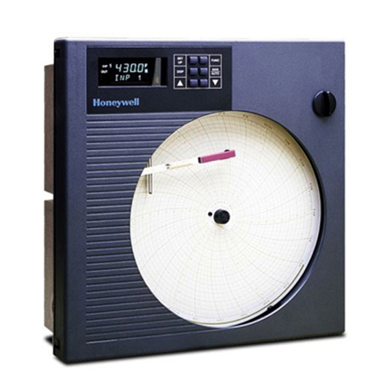
1.1 Introduction Function The DR4300 recorder is a one or two pen microprocessor-based circular chart recorder. The basic DR4301 (one pen) and DR4302 (two pen) recorders provide reliable, convenient pen-drawn analog traces on preprinted 10 inch (250 mm) charts. Both the chart and the pens are driven by stepper motors controlled by the microprocessor. - Page 14 The upper display uses four characters to display the input value. The lower display shows other parameters using a two- or three-character label and four- or three- digit values. In addition, status and error messages flash on the lower display when necessary. DR4300 Circular Chart Recorder Product Manual 4/00...
- Page 15 Construction All DR4300 recorders are housed in a rugged molded case which can be panel-, pipe- or surface-mounted. An acrylic-windowed, gasketed door protects internal components from harsh environments while allowing easy access to the chart.
-
Page 16: Model Number Breakdown
- _ _ _ _ - _ _ _ _ _ - _ _ _ _ - _ _ _ _ - Key numbers The base model numbers for the DR4300 Circular Chart Recorder are: One Pen Recorder (Basic Recorder Without Display) - Page 17 _ _ T _ Output Type Pen 2 None _ _ _ 0 Electromechanical Relay _ _ _ E Solid State Relay _ _ _ S Open Collector _ _ _ T 4/00 DR4300 Circular Chart Recorder Product Manual...
- Page 18 _ _ _ _ 0 Configuration for Non-Standard Range Settings _ _ _ _ 1 (see Note 6) Configuration for Customer’s Specific Data _ _ _ _ 2 (see Note 6) DR4300 Circular Chart Recorder Product Manual 4/00...
- Page 19 No Certificate Certificate of Conformance (F3391) Certificate of Calibration (F3399) (See Note 2) Certificate of Conformance and Calibration (See Note 2) 4/00 DR4300 Circular Chart Recorder Product Manual...
- Page 20 For example: Pen 1: "J" Thermocouple, 0-375 °F, 7-Day Linear Chart Pen 2: 4-20 mA, 0-1000, 7-Day Linear Chart For configuration on Models DR4311, DR4312, DR4331, and DR4332, the customer must supply completed "Configuration Worksheets" with order for units to be Factory configured. DR4300 Circular Chart Recorder Product Manual 4/00...
-
Page 21: About This Manual
Unless a section’s title refers to recorders “without display” or “with display”, the information in the section applies to all models. To see which sections apply to your recorder, see Figure 1-1. 4/00 DR4300 Circular Chart Recorder Product Manual... -
Page 22: Figure 1-1 Guide To Manual's Organization
Alignment of Recorder without Display Alignment of Recorder with Display 9 - Parts List SECTION Options Setpoint Ramp/Soak APPENDIX C - Programming and Operation Using Accutune II APPENDIX D - 24209 Figure 1-1 Guide to Manual’s Organization DR4300 Circular Chart Recorder Product Manual 4/00... -
Page 23: Installation
2. Installation 2.1 Overview Introduction Installation of the DR4300 recorder consists of mounting and wiring the recorder according to the instructions given in this section. Read the pre-installation information below, check the model number interpretation in Section 1, and become familiar with your model selections, then proceed with installation. -
Page 24: Table 2-1 Operating Limits And Condensed Specifications
250 ohms Vdc: 200K ohms RTD: 13.3 K ohms All others: 10 Megohms Span Step Response Time 7 seconds maximum Reproducibility 0.1 percent of span Sampling Rate Input sampled 3 times per second DR4300 Circular Chart Recorder Product Manual 3/00... - Page 25 SPDT contacts. Internally socketed. Output Resistive Load: 5 A @ 120 Vac or 2.5 A @ 240 Vac or 30 Vdc. Inductive Load: 50 VA @ 120 Vac or 240 Vac. Motor: 1/6 H.P. 3/00 DR4300 Circular Chart Recorder Product Manual...
- Page 26 On contact closure the recorder will respond according to how each digital input is configured. Opening contact causes return to previous state. Transmitter Power 24 Vdc with adjustment of ± 6 % (22.6 to 25.4) 100 mA maximum output DR4300 Circular Chart Recorder Product Manual 3/00...
-
Page 27: Mounting Considerations And Overall Dimensions
17.5 147.8 355.6 14.0 14.5 Short wing latch 0.57 Double bit latch 0.19 369.6 14.5 196.2 322.56 12.70 163.2 181.3 322.56 Panel Surface 12.70 Cutout Mounting Rear View 24210 Figure 2-1 Overall Dimensions 3/00 DR4300 Circular Chart Recorder Product Manual... -
Page 28: Mounting Methods
1/2" (12.7 mm) conduits. Refer to Figure 2-2 for plug locations. To see recommended use of conduits for various types of wiring, refer to Figure 2-7 and Figure 2-8. Side View Bottom View 24211 Figure 2-2 Plug Locations DR4300 Circular Chart Recorder Product Manual 3/00... -
Page 29: Mounting Flush In Panel (New Panel Cutout)
While holding the recorder firmly against the panel, slide each bracket against the back of the panel and tighten the screws. Hex screw, 1/4-20 x 1/2 inch and washer 21406 Figure 2-3 Mounting Flush in a New Panel Cutout (Rear View) 3/00 DR4300 Circular Chart Recorder Product Manual... -
Page 30: Panel Mounting Recorder With Nema4 Or Heavy Duty Door
When completed all twelve screws should have a minimum of 10 lb-in of torque applied. This assures the case and panel gasket are adequately sealed against the panel. DR4300 Circular Chart Recorder Product Manual 3/00... -
Page 31: Figure 2-4 Panel Mounting Recorder With Nema4 Or Heavy Duty Door
Side View 1/4-20 x 3/8 inch NOTE: Mounting brackets and attaching hardware are included in kit 30755065-502; panel gasket supplied in kit 51197657-501. Figure 2-4 Panel Mounting Recorder with NEMA4 or Heavy Duty Door 3/00 DR4300 Circular Chart Recorder Product Manual... -
Page 32: Mounting On A 2-Inch Pipe
Install the U-bolts around the pipe and through the bracket holes. Secure with lockwashers and hex nuts provided. Pipe Mounting Washer Bracket Plastite Hex Nut Screw Rear Case U-bolt 24224 Figure 2-5 Pipe Mounting Brackets DR4300 Circular Chart Recorder Product Manual 3/00... -
Page 33: Mounting On Surface (Of Panel Or Wall)
Hang the recorder on the screw by the support hook and insert the other two user-supplied screws through the brackets into the panel. Tighten the two hex screws that attach the brackets to the case. 3/00 DR4300 Circular Chart Recorder Product Manual... -
Page 34: Wiring Prerequisites
To minimize electrical noise and transients that may adversely affect the recorder, connection of the recorder terminal (located in the rear of the case) to a local earth (ground) using a No. 11 (4 mm ) braided copper conductor is recommended. DR4300 Circular Chart Recorder Product Manual 3/00... - Page 35 Cable/conduit entry fittings shall effectively terminate the cable shield connecting the shield to the enclosure conductive coating. The shielded cable shield shall not extend into the instrument closure. 3/00 DR4300 Circular Chart Recorder Product Manual...
-
Page 36: Figure 2-7 Recommended Wiring Routing - Models Without Ce Mark
Relay/Alarm A.C. Mains Outputs (Integral wiring Digital Inputs 1 and 2 to TB1) Current Outputs 1 and 2 and 24 V Power Supply Figure 2-7 Recommended Wiring Routing - Models Without CE Mark DR4300 Circular Chart Recorder Product Manual 3/00... -
Page 37: Figure 2-8 Recommended Wiring Routing - Models With Ce Mark
1 A braided copper shield shall be connected to ground (green screw on the filter assembly). A separate braided copper shield shall be used to connect on rear of case to chassis ground Figure 2-8 Recommended Wiring Routing - Models With CE Mark 3/00 DR4300 Circular Chart Recorder Product Manual... -
Page 38: Table 2-6 Wiring Bundling Categories
Figure 2-11 Digital Input Wiring Figure 2-12 Communication Wiring Figure 2-13 Relay Output Wiring Figure 2-14 Open Collector Relay Output Wiring Figure 2-15 Current Output Wiring Figure 2-16 Transmitter Power Out Wiring Figure 2-17 DR4300 Circular Chart Recorder Product Manual 3/00... -
Page 39: Input Wiring
The switch or circuit-breaker shall be located in close proximity to the recorder, within easy reach of the operator. The switch or circuit-breaker shall be marked as the disconnecting device for the recorder. 3/00 DR4300 Circular Chart Recorder Product Manual... -
Page 40: Table 2-8 Procedure For Power Wiring Models
Refer to Appendix A for additional information concerning noise interference prevention. WARNING SHOCK HAZARD Input line voltage may be present on the instrument ground plane if earth ground is not attached. Failure to observe this precaution can result in serious personal injury. DR4300 Circular Chart Recorder Product Manual 3/00... -
Page 41: Figure 2-9 Power Wiring - Models Without Ce Mark
4 For 2 Pen Recorder/Controller, connect ac power to TB1 of Pen 2 PCA. Supply connections must be made at TB6, if installed. Wire ac power to this connector if installed. Figure 2-9 Power Wiring – Models Without CE Mark 3/00 DR4300 Circular Chart Recorder Product Manual... -
Page 42: Figure 2-10 Power Wiring - Models With Ce Mark
(located in the rear of the case) to a local earth L1/H L2/N (ground), using a No. 11 (4 mm ) braided copper conductor, is required. 100 Vac to 240 Vac Figure 2-10 Power Wiring – Models With CE Mark DR4300 Circular Chart Recorder Product Manual 3/00... -
Page 43: Analog Input Wiring
Tighten the screws to secure the wires. If the recorder has two pens, repeat Steps 3 through 6 to wire the input for the second pen channel to TB2 on the PCA on the left inside of the recorder. 3/00 DR4300 Circular Chart Recorder Product Manual... -
Page 44: Figure 2-11 Analog Input Wiring
Standard used as color the other two. The single wire is usually reference ANSI MC96.1 the positive connection mA, mV or Volt mA, mV or – Volt source Figure 2-11 Analog Input Wiring DR4300 Circular Chart Recorder Product Manual 3/00... -
Page 45: Digital Inputs (Optional)
Insert the wires under the appropriate screws for the input number (labeled on assembly). Tighten the screws to secure the wires. If the recorder has two pens, repeat Steps 2 through 5 to wire the input for the second pen channel. 3/00 DR4300 Circular Chart Recorder Product Manual... -
Page 46: Figure 2-12 Digital Input Wiring
Main PCA Pen 2 Pen 1 Digital Input PCA 24142 Digital Input Switch #1 Digital Input Switch #2 Connect shield to ground at one end only Switch Common Figure 2-12 Digital Input Wiring DR4300 Circular Chart Recorder Product Manual 3/00... -
Page 47: Communication (Optional)
Strip 1/4-inch maximum of insulation from the end of each wire and form end to fit under a screw connection. Insert the wires under the appropriate screws (labeled on assembly). Tighten the screws to secure the wires. 3/00 DR4300 Circular Chart Recorder Product Manual... -
Page 48: Figure 2-13 Communication Wiring
NOTE: The shield of the To other communication cable is connected to ground at the recorder end, and communications should not extend into the recorder instruments enclosure. (Maximum 15) Optional communication Figure 2-13 Communication Wiring DR4300 Circular Chart Recorder Product Manual 3/00... -
Page 49: Output Wiring
Normally Open (NO) and Normally Closed (NC) operation. ATTENTION The DR4300 is available as a limit controller. In a limit controller each pen channel’s printed circuit assembly Relay 1 (TB4 terminals 3 and 2 for NO contacts, and 2 and 1 for NC contacts) is used for limit control. -
Page 50: Table 2-13 Relay Output Wiring - 1 Or 2 Pen Models
Insert the wires under the appropriate screws for the applicable relay output as shown in the figures. Tighten the screws to secure the wires. *TB3 is output 2. TB4 is output 1. DR4300 Circular Chart Recorder Product Manual 3/00... -
Page 51: Figure 2-14 Relay Output Wiring
Use a dummy resistor as shown to counteract this. The total current through the resistor and the load current must exceed 20 mA. Solid State relays are rated at 0.5 Amps. Size fuses accordingly. Figure 2-14 Relay Output Wiring 3/00 DR4300 Circular Chart Recorder Product Manual... -
Page 52: Figure 2-15 Open Collector Output Wiring
Main PCA Pen 2 Pen 1 24145A 0 to 30 Vac 0 to 30 Vac – – – – Customer Supplied Electromechanical Relay Customer Supplied Solid State Relay Figure 2-15 Open Collector Output Wiring DR4300 Circular Chart Recorder Product Manual 3/00... -
Page 53: Current Output
Strip 1/4-inch maximum of insulation from the end of each wire and form end to fit under a screw connection. Insert the wires under the appropriate screws for the applicable relay output as shown in the figure. Tighten the screws to secure the wires. 3/00 DR4300 Circular Chart Recorder Product Manual... -
Page 54: Figure 2-16 Current Output Wiring
DR4300 Circular Chart Recorder Main PCA Main PCA Pen 1 Pen 2 24824 Current Output Auxiliary Output Load 0-600 Ohms Figure 2-16 Current Output Wiring DR4300 Circular Chart Recorder Product Manual 3/00... -
Page 55: Transmitter Power Out
Strip 1/4-inch maximum of insulation from the end of each wire and form end to fit under a screw connection. Insert the wires under the appropriate screws for the transmitter power out as shown in the figure. Tighten the screws to secure the wires. 3/00 DR4300 Circular Chart Recorder Product Manual... -
Page 56: Figure 2-17 Transmitter Power Out Wiring
NOTE: Ensure switches on SW6 are set to their correct positions prior to applying power to transmitter supply. For switch settings see Table 3-2 (recorders without display) or Table 4-3 (recorders with display). DR4300 Circular Chart Recorder Product Manual 3/00... -
Page 57: Configuration, Startup, And Operation Of Basic Recorder Without Display
POWER DISCONNECTED. DO NOT TOUCH POWER CONNECTIONS AT TB1. FAILURE TO OBSERVE THIS PRECAUTION CAN RESULT IN EXPOSURE TO A POTENTIALLY LETHAL SHOCK HAZARD. MORE THAN ONE SWITCH MAY BE REQUIRED TO DE-ENERGIZE UNIT. 4/00 DR4300 Circular Chart Recorder Product Manual... -
Page 58: Configuration (Recording Set Up)
For each PCA, make a note of the number assigned to the configuration (from first column of Table 3-2). If you have to call Honeywell Technical Assistance for help, tell the support staff the configuration number(s) of the pen channel(s) in your recorder to speed up the troubleshooting process. -
Page 59: Figure 3-1 Location Of Configuration And Input Switches
Connector Jumper Configuration Switches LOWER RAISE S2 = Reset S3 = Lower S4 = Raise Input Switches SETUP AC Power Input Connector Run/Setup Switch 24194 Figure 3-1 Location of Configuration and Input Switches 4/00 DR4300 Circular Chart Recorder Product Manual... -
Page 60: Figure 3-2 Sample Chart For Single Pen Recorder
X = Don’t care 0 TO 150 C J /T/C 24082 Summary of Input Set Up Switch S6 Functions 200 mV Burnout Volts Figure 3-2 Sample Chart for Single Pen Recorder DR4300 Circular Chart Recorder Product Manual 4/00... -
Page 61: Table 3-2 Configuration And Input Switch Settings For Models Without Display
Any linear chart 2-10 12 Hr Volt o n o o n n o o o x o n o o 0-20 Any linear chart 12 Hr 4/00 DR4300 Circular Chart Recorder Product Manual... - Page 62 0-10 Any linear chart 24001661-tab 7 Day Volt n n o n o o o o o x o n o o Any linear chart 24001661-tab 7 Day Volt DR4300 Circular Chart Recorder Product Manual 4/00...
- Page 63 0 to 200 Even °C 1660-010 J t/c 24 Hr n n n o o o o n o x o o n o J t/c 0 to 200 Even °F 1661-004 7 Day 4/00 DR4300 Circular Chart Recorder Product Manual...
- Page 64 0 to 400 Even °F 1660-011 J t/c 24 Hr n n o n n o o n o x o o n o 0 to 400 Even °C 1660-011 J t/c 24 Hr DR4300 Circular Chart Recorder Product Manual 4/00...
- Page 65 0 to 1200 °F 1660-004 J t/c 24 Hr o n n o o o n o o x o o n o 0 to 1200 °F 1661-011 J t/c 7 Day 4/00 DR4300 Circular Chart Recorder Product Manual...
- Page 66 K t/c 0 to 500 °F 24 Hr o n o o o n n o o x o o n o K t/c 0 to 500 °C 1660-205 24 Hr DR4300 Circular Chart Recorder Product Manual 4/00...
- Page 67 K t/c 0 to 1600 °F 1661-013 7 Day o o n o n n o n o x o o n o K t/c 0 to 1600 Even °F 1661-109 7 Day 4/00 DR4300 Circular Chart Recorder Product Manual...
- Page 68 –25 to 25 Even °C 7 Day n o n o o o o o o o n o n o RTD* –100 to 50 °C 1660-091 24 Hr DR4300 Circular Chart Recorder Product Manual 4/00...
- Page 69 –100 to 100 Even °F 7 Day o n o o n n n o o o n o n o 0 to 100 Even °C 1660-001 24 Hr 4/00 DR4300 Circular Chart Recorder Product Manual...
- Page 70 –40 to 200 Even °C 24 Hr n n o n n n n o o o n o n o –40 to 200 Even °C 7 Day DR4300 Circular Chart Recorder Product Manual 4/00...
- Page 71 0 to 300 Even °F 1661-050 7 Day o n o n n o n n o o n o n o 0 to 350 Even °F 1660-037 24 Hr 4/00 DR4300 Circular Chart Recorder Product Manual...
- Page 72 S t/c 0 to 3000 °F 1660-147 24 Hr o o o n n o n o o x o o n o 0 to 3000 °F 1661-147 S t/c 7 Day DR4300 Circular Chart Recorder Product Manual 4/00...
- Page 73 –100 to 100 Even °F T t/c 7 Day n o n n o n n n o x o o n o 0 to 100 Even °F 1660-001 T t/c 24 Hr 4/00 DR4300 Circular Chart Recorder Product Manual...
- Page 74 T t/c 24 Hr (dual range chart) n o n o n o o o o x o o n o –125 to 375 Even °F 1661-194 T t/c 7 Day (dual range chart) DR4300 Circular Chart Recorder Product Manual 4/00...
- Page 75 **If you set the switches in an ON/OFF combination that does not match any of the given configurations, the recorder will default to configuration #1. ***Refer to Figure 3-1 for location of jumper R56. 4/00 DR4300 Circular Chart Recorder Product Manual...
-
Page 76: Setting Sw6 Switch 2
It is important, however, to set the switch to OFF in the case of RTD actuation. ATTENTION If SW6 switch 2 is ON for an RTD input, the recorder will not be able to process the input accurately, even when the input sensor is providing a valid signal. DR4300 Circular Chart Recorder Product Manual 4/00... -
Page 77: Startup And Operation Of Recorder Without Display
POWER DISCONNECTED. DO NOT TOUCH POWER CONNECTIONS AT TB1. FAILURE TO OBSERVE THIS PRECAUTION CAN RESULT IN EXPOSURE TO A POTENTIALLY LETHAL SHOCK HAZARD. MORE THAN ONE SWITCH MAY BE REQUIRED TO DE-ENERGIZE UNIT. 4/00 DR4300 Circular Chart Recorder Product Manual... -
Page 78: Preparing The Recorder For Operation
1 before closing the locking clip on the hub. Push down on the lifter to return the pen(s) to the chart. CAUTION: Do not try to rotate the hub. Time index Pen lifter Large chart 24213 Figure 3-3 Basic Chart Plate Components DR4300 Circular Chart Recorder Product Manual 4/00... -
Page 79: Running The Optional Step Test
At the conclusion of the test turn off the power to the recorder. 4/00 DR4300 Circular Chart Recorder Product Manual... -
Page 80: Figure 3-4 Typical Step Test Chart Patterns
Chart step pattern Figure 3-4 is a typical chart step pattern generated by the recorder in the step test. 24141 Figure 3-4 Typical Step Test Chart Patterns DR4300 Circular Chart Recorder Product Manual 4/00... -
Page 81: Startup
Close the door and apply power. The pen(s) will move into position and the recorder will start to track the input value. Time index Pen lifter Large chart 24212 Figure 3-5 Setting Chart Time to Time Index 4/00 DR4300 Circular Chart Recorder Product Manual... - Page 82 DR4300 Circular Chart Recorder DR4300 Circular Chart Recorder Product Manual 4/00...
-
Page 83: Configuration, Startup And Operation Of Recorder With Display
4. Configuration, Startup and Operation of Recorder with Display 4.1 Overview Introduction This section provides instructions for configuring, starting, and operating DR4300 recorder models having a display and keypad. What’s in this section? The following is a list of topics covered in this section. -
Page 84: Operator Interface On Recorder With Display And Keypad
When either of the remote switches is set for SP2, or when NumSPs = TWO L = Setpoint 1 (SP) active R = Setpoint 2 (S2) active Otherwise, neither indicator 24278 is used. Figure 4-1 Operator Interface DR4300 Circular Chart Recorder Product Manual 4/00... -
Page 85: Table 4-1 Key Functions
(once the cause of the limit state has been corrected) and to cause it to resume normal operation, monitoring the value of the input and comparing it to the configured limit value. 4/00 DR4300 Circular Chart Recorder Product Manual... -
Page 86: Configuration (Recording And Output Set Up)
If an optional relay is used, then it can be wired for Normally Open and Normally Closed action. Hardware switches must be set to match the input type, and to specify input state in case of input failure. DR4300 Circular Chart Recorder Product Manual 4/00... -
Page 87: Configuration Prompts
PERIOD START L DISP ALARMS A1S1TY A1S2TY A1S1VA A1S2VA A1S1HL A1S2HL A1 HYS A2S1TY A2S2TY A2S1VA A2S2VA A2S1HL A2S2HL A2 HYS AUXOUT AUXOUT 4mA VA 20mA V COMM COMM ADDRES BAUD XmtDLY DBLBYT 4/00 DR4300 Circular Chart Recorder Product Manual... - Page 88 Function Prompts REM SW REMSW1 REMSW2 DSPLAY BLANK TOGGLE LOCK LOCK For pen alignment—see Section 8 of manual ALIN For field calibration—see Section 5 of manual For status displays—see Section 8 of manual STATUS DR4300 Circular Chart Recorder Product Manual 4/00...
-
Page 89: How To Get Started
It allows you to quickly find a parameter and determine the appropriate value or selection for your application. Complete configuration record sheet Subsection 4.3.21 contains a “Configuration Record Sheet”. It is good practice to record your instrument’s configuration for future reference. 4/00 DR4300 Circular Chart Recorder Product Manual... -
Page 90: Configuration Tips
If you are in Set Up (configuration) mode and do not press any keys for one Timing out from minute, the recorder will time out and revert to the mode and display that Set Up mode was being used prior to entry into Set Up mode. DR4300 Circular Chart Recorder Product Manual 4/00... -
Page 91: Switch Settings
POWER DISCONNECTED. DO NOT TOUCH POWER CONNECTIONS AT TB1. FAILURE TO OBSERVE THIS PRECAUTION CAN RESULT IN EXPOSURE TO A POTENTIALLY LETHAL SHOCK HAZARD. MORE THAN ONE SWITCH MAY BE REQUIRED TO DE-ENERGIZE UNIT. 4/00 DR4300 Circular Chart Recorder Product Manual... -
Page 92: Table 4-3 Sw6 Input Switch Settings For Models Having Display And Keypad
RTDs This switch is used to select whether the input value used by the recorder should be driven over range or under range in case of input failure. See Subsection 4.3.5.3. DR4300 Circular Chart Recorder Product Manual 4/00... - Page 93 “UP” or “DOWN”, configured for “BRNOUT”. The displayed value (over range or under range) as configured in “BRNOUT”, will remain on the display until a valid input is restored. 4/00 DR4300 Circular Chart Recorder Product Manual...
-
Page 94: Figure 4-3 Location Of Switches And Relays
S4 = Raise Input Switches SETUP AC Power Input Connector Run/Setup Switch* *Also used as a lockout switch in the “SETUP” position. 24084 Relay Output Current Output/Aux. Output Figure 4-3 Location of Switches and Relays DR4300 Circular Chart Recorder Product Manual 4/00... -
Page 95: Configuration Procedure
Lower Display DECMAL Shows the first function prompt within the selected set up group. Example displays show Input group function prompt “DECMAL” and the value selected. 4/00 DR4300 Circular Chart Recorder Product Manual... - Page 96 2-Pen Recorders For 2-pen recorders, press FUNC key to select INP 2 FUNC for display and return to step 1 to configure the parameters for pen 2. DR4300 Circular Chart Recorder Product Manual 4/00...
-
Page 97: Input Parameters Set Up Group
TYP” parameter must be for a linear input type for two decimal places to be displayed. UNITS TEMPERATURE UNITS—This selection will be indicated on the PV display. NONE No units [factory setting] Degrees Fahrenheit Degrees Celsius 4/00 DR4300 Circular Chart Recorder Product Manual... - Page 98 0 to 5000 and the input type is 0 to 5 volts. Then if input = 2.5 V = 50 %, .50 .7071 70.71% .7071 x 5000 = 3535 = PV DR4300 Circular Chart Recorder Product Manual 4/00...
- Page 99 No filter = 0 input to smooth the input signal. You can configure the first order lag time constant from 1 to 120 seconds. If you do not want [factory setting = 0] filtering, enter 0. 4/00 DR4300 Circular Chart Recorder Product Manual...
- Page 100 Upscale and the lower display will alternate between: INP#, Limit, and INP FL. If a LO limit is configured and the input opens, the input reading will go down scale and the lower display will alternate between: INP#, Limit, and INP FL. DR4300 Circular Chart Recorder Product Manual 4/00...
-
Page 101: Pen Parameters Set Up Group
–999 to 9999 CHT LO CHART RANGE LOW VALUE—Enter a value that corresponds with the chart low range value for the [factory setting = 730] pen. 4/00 DR4300 Circular Chart Recorder Product Manual... -
Page 102: Chart Parameters Set Up Group
LIN [factory setting] Linear (even) or NLIN Non-Linear (i.e., J T/C or RTD) ATTENTION LIN chart type is automatically selected when input type is linear (as defined by value of input set up parameter “INTYP”). DR4300 Circular Chart Recorder Product Manual 4/00... -
Page 103: Totalizer Parameters Set Up Group
TOTALIZATION FOR INPUT—This parameter is used to enable or disable the totalizer function. This prompt appears DIS [factory setting] first if “DIS” is the current choice. ENABLE allows configuration of the rest of the prompts associated with totalization. 4/00 DR4300 Circular Chart Recorder Product Manual... - Page 104 1E5 equals 1 times 10 (100,000) 1E6 (displays as E6) 1E6 equals 1 times 10 (1,000,000) 1E7 (displays as E7) 1E7 equals 1 times 10 (10,000,000) 1E8 (displays as E8) 1E8 equals 1 times 10 (100,000,000) DR4300 Circular Chart Recorder Product Manual 4/00...
- Page 105 “REMSW2” in the remote switch set up group. 0 % to 100 % CUTOFF LOW CUTOFF VALUE—Input % of range below which the totalizer stops accumulating. *Digital input card must be installed. 4/00 DR4300 Circular Chart Recorder Product Manual...
-
Page 106: Control Parameters Set Up Group
0 % to 50 % output (tuning set 2) and relay active 50 % to 100 % output (tuning set Control group functions “CURRNG” and "DBAND" are affected. DR4300 Circular Chart Recorder Product Manual 4/00... - Page 107 (“HYST”) of the ON and OFF states of each output. With no relay action the controller output will read 50 %. 4/00 DR4300 Circular Chart Recorder Product Manual...
- Page 108 AUTO AUTOMATIC—At power-up, the recorder will return to the automatic mode. [factory setting] DEFDSP DEFAULT DISPLAY—This selection determines the default display (input or active setpoint) on power up. DR4300 Circular Chart Recorder Product Manual 4/00...
- Page 109 ON/OFF states of each control relay. This [factory setting = 0] is the difference between the value of the process variable at which the control relays energize and the value at which they de-energize. Only applicable for ON/OFF control. 4/00 DR4300 Circular Chart Recorder Product Manual...
- Page 110 PBorGN to GAIN, the value of tuning parameter “GAIN” will now be 20 (the value formerly assigned to “PB”). If you want the same control action you had before, you must change the value of “GAIN” to 5. DR4300 Circular Chart Recorder Product Manual 4/00...
- Page 111 MINRPM to I MIN, the value of “I MIN” will now be 2 (the value formerly assigned to “I RPM”). If you want the same control action you had before, you must change the value of “I MIN” to 0.5. 4/00 DR4300 Circular Chart Recorder Product Manual...
-
Page 112: Tuning Parameters Set Up Group
The fuzzy logic observes the speed and direction of the PV signal as it approaches the setpoint and temporarily modifies the internal controller response action as necessary to avoid an overshoot. There is no change to the PID algorithm, and the fuzzy logic does not alter the PID tuning parameters. DR4300 Circular Chart Recorder Product Manual 4/00... -
Page 113: Table 4-10 Tuning Parameter Definitions
“CurT” (current/time duplex), and you are using the recorder in a heat/cool application, PB or GAIN is used for heat control. Cooling control would use PB2 or GAIN 2 described later in this table. 4/00 DR4300 Circular Chart Recorder Product Manual... - Page 114 (offset) from setpoint. This reset value can be used to eliminate the offset and lets the PV line out at setpoint. The controller output is the computed output plus the value of MANRST. DR4300 Circular Chart Recorder Product Manual 4/00...
- Page 115 “OUTALG” [factory setting = 4] is set to RLYD (relay duplex). ATTENTION If you are using the recorder in a heat/cool application, CYC2TI is used for control of cooling. 4/00 DR4300 Circular Chart Recorder Product Manual...
-
Page 116: Setpoint Ramp/Program Set Up Group
Available only with controllers that contain this option. DIS [factory setting] For reasons of convenience, the information for the prompts when SPPROG is enabled are included in Appendix C. ATTENTION “SP RAMP” must be disabled for SPPROG to be available. DR4300 Circular Chart Recorder Product Manual 4/00... -
Page 117: Timer Set Up Group
“clock” character. TREM [factory setting] Time remaining: If the “clock” rotation is clockwise, elapsed time is indicated. Elased time: If the “clock” rotation is counterclockwise, time left is indicated. 4/00 DR4300 Circular Chart Recorder Product Manual... -
Page 118: Alarms Set Up Group
ALARM 1 SETPOINT 2 VALUE—This is the value at which you want the alarm type chosen in prompt [factory setting = 100] "A1S2TY" to actuate. The appropriate value depends on what the setpoint has been configured to represent. DR4300 Circular Chart Recorder Product Manual 4/00... - Page 119 "A2S2TY" to alarm high or low. [factory setting] HI ALARM—Relay coil is de-energized when the PV is above the setpoint. LO ALARM—Relay coil is de-energized when the PV is below the setpoint. 4/00 DR4300 Circular Chart Recorder Product Manual...
- Page 120 ON, it will not deactivate until the variable is away from the alarm setpoint by a value equal to A2 HYS. Configure the hysteresis as a percent of input range span. DR4300 Circular Chart Recorder Product Manual 4/00...
-
Page 121: Auxiliary Output Set Up Group
Type “J” Thermocouple (0 °F to 1600 °F) 0 °F display = 0 % output 1600 °F display = 100 % output OUTPUT—Represents the displayed controller output in percent (%). SETPOINT—Represents the value of the setpoint in units of PV. 4/00 DR4300 Circular Chart Recorder Product Manual... - Page 122 20 mA output. Zero deviation will produce a center scale (12 mA) output. A negative deviation equal in magnitude to the Auxiliary Output High Value will provide a low end (4 mA) output. DR4300 Circular Chart Recorder Product Manual 4/00...
-
Page 123: Communication Set Up Group
DBLBYT DOUBLE BYTE ORDER—Determines Floating Point Byte order in Modbus queries. FP B Big Endian FP BB Big Endian – Byte Swapped FP L Little Endian FP LB Little Endian – Byte Swapped 4/00 DR4300 Circular Chart Recorder Product Manual... -
Page 124: Remote Switch (Digital Inputs) Set Up Group
For a 2-pen recorder, the desired input channel is displayed on the left side of the operator interface. Press FUNC to select channel. Press SETUP key until “REM SW” appears in the lower display. Press FUNC key to select the parameters. DR4300 Circular Chart Recorder Product Manual 4/00... -
Page 125: Table 4-16 Remote Switch Parameter Definitions
REMOTE SWITCH 2—This parameter is used to specify what action the recorder should take if digital input 2 for this channel goes ON (switch contact closed). The MNFS choices are the same as for REMSW1. HOLD TIMR 4/00 DR4300 Circular Chart Recorder Product Manual... -
Page 126: Display Parameter Set Up Group
OFF disables the function. OFF [factory setting] TOGGLE TOGGLE FUNCTION—Use this parameter to set the timeout period after which control the display is passed to the other board (pen). DR4300 Circular Chart Recorder Product Manual 4/00... -
Page 127: Lock Out Parameter Set Up Group
The Lock function cannot be changed when the RUN/SETUP switch is in the "SETUP" position, making it usable as a physical lockout. Whatever lockout level is selected, it is protected as long as the switch is in the SETUP position. 4/00 DR4300 Circular Chart Recorder Product Manual... -
Page 128: Configuration Record Sheet
Remember that not all function parameters apply to every recorder and configuration. The prompts for the optional 24-segment setpoint program option are not included on this record sheet. See Appendix C for a special worksheet used for this feature. DR4300 Circular Chart Recorder Product Manual 4/00... - Page 129 __________ __________ DSPLAY BLANK __________ __________ TUNING FUZZY __________ __________ TOGGLE __________ __________ TUNE __________ __________ LOCK LOCK __________ __________ AT ERR __________ __________ PB or GAIN __________ __________ RATE T _________ __________ 4/00 DR4300 Circular Chart Recorder Product Manual...
-
Page 130: Limit Control Configuration
Special configuration for control and alarms The DR4300 is available as a limit controller. Most set up groups described in Subsections 4.3.7 through 4.3.20 apply to limit control, and are configured for the limit controller the same way they are for other recorders. -
Page 131: Startup Of Recorder With Display And Keypad
WARNING—SHOCK HAZARD STARTUP AND MAINTENANCE MAY REQUIRE ACCESS TO HAZARDOUS LIVE CIRCUITS, AND SHOULD ONLY BE PERFORMED BY QUALIFIED SERVICE PERSONNEL. MORE THAN ONE SWITCH MAY BE REQUIRED TO DE-ENERGIZE UNIT BEFORE SERVICING. 4/00 DR4300 Circular Chart Recorder Product Manual... -
Page 132: Preparing The Recorder For Startup
1 before closing the locking clip on the hub. Push down on the lifter to return the pen(s) to the chart. CAUTION: Do not try to rotate the hub Time index Pen lifter Large chart 24213 Figure 4-4 Basic Chart Plate Components DR4300 Circular Chart Recorder Product Manual 4/00... -
Page 133: Running The Optional Step Test
Be certain that the Lockout level is "CAL" or "NONE". The self-test will not run otherwise. Apply power to the recorder. Until INP 1 indicator is lit on the left side of the operator interface. FUNC 4/00 DR4300 Circular Chart Recorder Product Manual... -
Page 134: Figure 4-5 Typical Step Test Chart Patterns
Terminates the test at any time. DISP Chart step pattern Figure 4-5 is a typical chart step pattern generated by the recorder in the test. 24141 Figure 4-5 Typical Step Test Chart Patterns DR4300 Circular Chart Recorder Product Manual 4/00... -
Page 135: Completing Preparation And Startup
The pen(s) will move into position and the recorder pen will start to track the value specified using the “PENIN” parameter in the pen set up group (see Subsection 4.3.8). Time index Pen lifter Large chart 24212 Figure 4-6 Setting Chart Time to Time Index 4/00 DR4300 Circular Chart Recorder Product Manual... -
Page 136: Table 4-23 Power-Up Diagnostic Tests
2 assembly fails one of the tests, the message “P2 ERR” will be displayed, along with any error messages from the pen 1 tests. Section 8 contains additional information about self-diagnostics, and suggested remedies if a problem is detected. DR4300 Circular Chart Recorder Product Manual 4/00... -
Page 137: Table 4-24 Procedure For Testing The Displays And Keys
• The recorder is not in Set Up mode, so the recorder can not respond to the key; press the SET UP key first. • The key is not valid because the recorder is not set up for control. • The key malfunctions; perform keypad test. 4/00 DR4300 Circular Chart Recorder Product Manual... -
Page 138: Table 4-25 Procedure For Starting The Recorder
If you want to check the recorder’s configuration, configuration. follow the procedure described earlier in this section. If you try to change a value and can not, a lockout is enabled; see Subsection 4.3.19. DR4300 Circular Chart Recorder Product Manual 4/00... - Page 139 For recorders with two control outputs enabled, repeat steps 2 to 6 for the second control output, but be sure INP “2” indicator is lit instead of INP “1”. Exit Startup Close the door and monitor the operation. 4/00 DR4300 Circular Chart Recorder Product Manual...
-
Page 140: Operation Of Recorder With Display And Keypad
When either of the remote switches is set for SP2, or when NumSPs = TWO L = Setpoint 1 (SP) active R = Setpoint 2 (S2) active Otherwise, neither indicator 24278 is used. Figure 4-7 Operator Interface DR4300 Circular Chart Recorder Product Manual 4/00... -
Page 141: Table 4-26 Meaning Of Indicators
Indicates the temperature units of PV: F = Fahrenheit C = Celsius R or L L = Setpoint 1 (SP) active; R = Setpoint 2 (S2) active KEYERR Keystroke is invalid. (in lower display) 4/00 DR4300 Circular Chart Recorder Product Manual... -
Page 142: Table 4-27 Lower Display Operating Parameter Labels
Status of Accutune II. Displayed only if Accutune is enabled. See Appendix D for TuneON or detailed Accutune instructions. TuneOF * *You can press or to change the value or initiate some action when this parameter is displayed. DR4300 Circular Chart Recorder Product Manual 4/00... -
Page 143: Table 4-28 Error Messages
Appendix C, and the run or hold action was initiated locally. • If the lower display flashes “run n” or “hold”, the recorder is executing setpoint program “n”, and the run or hold action was initiated remotely. 4/00 DR4300 Circular Chart Recorder Product Manual... -
Page 144: Operator Functions
Remember that any value displayed for a 2-pen recorder will be identified by the “1” or “2” at the left of the display, indicating the pen channel to which the value applies. Press the FUNC key to toggle between pen channels. DR4300 Circular Chart Recorder Product Manual 4/00... -
Page 145: Table 4-29 Procedure For Selecting Automatic Or Manual Mode
Upper Display shows the input value. Lower Display shows OT and the output value in % for the selected channel. Return to automatic “A” indicator appears indicating automatic mode. mode AUTO RESET 4/00 DR4300 Circular Chart Recorder Product Manual... -
Page 146: Table 4-30 Procedure For Changing The Control Setpoints
Return to input 1 to light “INP 1” indicator parameters for FUNC display If remote switch is set to SP2 then DISP will allow setting of second setpoint (S2). DR4300 Circular Chart Recorder Product Manual 4/00... -
Page 147: Table 4-31 Procedure For Displaying Or Changing The Alarm Setpoints
(Alarm 2, Setpoint 1 value) A2S2 VA = (Alarm 2, Setpoint 2 value) Change any alarm setpoint value you select in the upper display. Return to normal Returns to normal operation. operation DISP 4/00 DR4300 Circular Chart Recorder Product Manual... -
Page 148: Table 4-32 Procedure For Selecting Factory Or Field Calibration Values
LD CAL is automatically set to FLD at the completion of the field calibration operation. Be sure the correct sensor is connected to the input terminals and resume normal operation. DR4300 Circular Chart Recorder Product Manual 4/00... -
Page 149: Table 4-33 Procedure For Resetting Totalizer
The recorder will return to the same state it was in before configuration (set up) mode was entered. DISP The value of the RESET parameter will automatically be returned to NO after the reset operation. 4/00 DR4300 Circular Chart Recorder Product Manual... -
Page 150: Table 4-34 Procedure For Starting Timer
4.5.2.7 Starting the Timer Introduction The DR4300 is available with an optional timer. This timer can be configured to be started by Alarm 1 or the keypad. (If the recorder supports digital inputs, one can be used to trigger the timer. This remote switch is independent of whether the timer is configured to start with the alarm or the keypad.) -
Page 151: Table 4-35 Procedure For Resetting Limit Controller
4.5.2.8 Resetting the Limit Controller Introduction The DR4300 is available as a limit controller. On each pen channel’s printed circuit assembly Relay 1 is used for limit control. When the recorder detects that the input has exceeded the limit (or fallen below the limit, depending on how the unit is configured) the controller goes to the limit state: Relay 1 is de-energized. - Page 152 DR4300 Circular Chart Recorder DR4300 Circular Chart Recorder Product Manual 4/00...
-
Page 153: Input And Output Calibration For Recorder With Display
5.6 Current Output Calibration WARNING—SHOCK HAZARD INPUT CALIBRATION MAY REQUIRE ACCESS TO HAZARDOUS LIVE CIRCUITS, AND SHOULD ONLY BE PERFORMED BY QUALIFIED SERVICE PERSONNEL. MORE THAN ONE SWITCH MAY BE REQUIRED TO DE-ENERGIZE UNIT BEFORE CALIBRATION. 4/00 DR4300 Circular Chart Recorder Product Manual... -
Page 154: Input Calibration Minimum And Maximum Range Values
Make sure the correct input is on display INP1 or INP2; use the key to select the input. FUNC Select the voltage or resistance equivalent for 0 % and 100 % range values from Table 5-1. Use these values when calibrating your recorder. DR4300 Circular Chart Recorder Product Manual 4/00... -
Page 155: Table 5-1 Voltage And Resistance Equivalents For 0 % And 100 % Range Values
*Range values for thermocouples are based on a cold junction temperature of 32 °F (0 °C). These values must be adjusted for the actual cold junction temperature when using the ambient temperature method for calibrating thermocouple inputs. ** IEC Alpha = 0.00385 *** Alpha = 0.00391 4/00 DR4300 Circular Chart Recorder Product Manual... -
Page 156: Input Calibration Preliminary Information
Milliamp, Millivolt, and Volts • A calibrating device with ± 0.02 % accuracy for use as a signal source. Inputs • Two insulated copper leads for connecting the calibrator to the recorder. DR4300 Circular Chart Recorder Product Manual 4/00... -
Page 157: Table 5-3 Disconnect The Field Wiring
Figure 5-1 for the location of the circuit boards and input connectors. Main PCA Main PCA Pen 2 Pen 1 24091 – Figure 5-1 Location of the Input Connections on the Input Boards 4/00 DR4300 Circular Chart Recorder Product Manual... -
Page 158: Input Calibration Set Up And Wiring
Route leads (for example: copper leads or thermocouple extension wires) through a conduit hole in the recorder case so that you will be able to close the chart plate. Close the chart plate after you have completed the applicable calibration set up. DR4300 Circular Chart Recorder Product Manual 4/00... -
Page 159: Thermocouple Inputs Using A Compensated Calibrator
Main PCA Main PCA Pen 2 Pen 1 24825 – Compensated Calibrator Thermocouple extension wires Figure 5-2 Calibration Set Up Diagram for Thermocouple Inputs Using a Compensated Calibrator 4/00 DR4300 Circular Chart Recorder Product Manual... -
Page 160: Thermocouple Inputs Using An Ice Bath Or Ice Point Reference
Main PCA Main PCA Pen 2 Pen 1 24092 – mV source Thermocouple Containers of Copper extension wires crushed ice wires Figure 5-3 Calibration Set Up Diagram for Thermocouple Inputs Using an Ice Bath DR4300 Circular Chart Recorder Product Manual 4/00... -
Page 161: Rtd (Resistance Temperature Detector) Inputs
Connect the other end of the copper wire to the TB2 terminals on the printed circuit assembly for the input channel being calibrated. Main PCA Main PCA Pen 2 Pen 1 24093 – Decade box Copper wires Figure 5-4 Calibration Set Up Diagram for RTD Inputs 4/00 DR4300 Circular Chart Recorder Product Manual... -
Page 162: Table 5-8 Set Up Wiring Procedure For Calibrating Millivolts, Volts, And Milliamps Inputs
Connect the other end of the copper wire to the TB2 terminals on the printed circuit assembly for the input channel being calibrated. Main PCA Main PCA Pen 2 Pen 1 24094 – Calibration source Copper wires Figure 5-5 Calibration Set Up Diagram for Millivolts, Volts, and Milliamps Inputs DR4300 Circular Chart Recorder Product Manual 4/00... -
Page 163: Input Calibration Procedure
If “CAL” doesn’t appear or prompt access is declined, check “LOCK” configuration. You will see: Upper Display FUNC Lower Display CAL IN The calibration sequence is enabled and you will see: Upper Display BEGIN Lower Display CAL IN 4/00 DR4300 Circular Chart Recorder Product Manual... - Page 164 The value of input set up group parameter “LD CAL” is set to “FLD” (field). The recorder begins to use the new field calibration values for this channel. Repeat this procedure for the other pen, if required. DR4300 Circular Chart Recorder Product Manual 4/00...
-
Page 165: Current Output Calibration
Close the chart plate: apply power and allow the recorder to warm up 15 minutes before you calibrate. Main PCA Main PCA Pen 2 Pen 1 24189 TB5 1 Milliammeter Figure 5-6 Test Equipment Connections for Calibrating Current Output 4/00 DR4300 Circular Chart Recorder Product Manual... -
Page 166: Table 5-11 Procedure For Calibrating Current Output
Upper Display FUNC a value (approximately 1800) Lower Display SPAN Until the desired 100 % output is read on the milliammeter. Use the values shown below depending on the action of your recorder. DR4300 Circular Chart Recorder Product Manual 4/00... - Page 167 Exit Calibration Mode The recorder stores the span value. FUNC Repeat procedure for the other pen. Remove power from recorder and disconnect the milliammeter and connect output wiring. To exit the calibration mode. DISP 4/00 DR4300 Circular Chart Recorder Product Manual...
- Page 168 DR4300 Circular Chart Recorder DR4300 Circular Chart Recorder Product Manual 4/00...
-
Page 169: Routine Maintenance
6.1 Overview Introduction Unless the recorder’s location will expose it to dust, the DR4300 recorder does not require any periodic maintenance except the replacement of the chart and ink cartridges. This section provides instructions for replacing the chart and ink cartridge. It also contains tips for maximizing the life of the pens, including recommended practices if the recorder is used in a dusty area. -
Page 170: Replacing The Chart
CAUTION: Do not try to rotate the hub Close the door and apply power. Notch for Open pen tip clip Pen arm Clip cartridge Time index Pen lifter Large chart 24214 Figure 6-1 Replacing the Chart and Ink Cartridge DR4300 Circular Chart Recorder Product Manual 4/00... -
Page 171: Replacing The Ink Cartridge
Slide the new cartridge onto the pen arm so that its tip fits into the notch at the end of the pen arm and close the clip to secure the cartridge to the pen arm. Push down the pen lifter to return the pen tip to the chart. Close the door and apply power. 4/00 DR4300 Circular Chart Recorder Product Manual... -
Page 172: Maximizing Pen Life
Be sure that the chart paper lays flat against the chart plate. Any ripple in the paper will cause light pen printing. Be sure the chart hub assembly is pushed onto the motor shaft so that it is flush with the chart plate. DR4300 Circular Chart Recorder Product Manual 4/00... -
Page 173: Troubleshooting And Pen Alignment Of Basic Recorder Without Display
7.4 Alignment of Pen at Zero and 100 % WARNING—SHOCK HAZARD TROUBLESHOOTING MAY REQUIRE ACCESS TO HAZARDOUS LIVE CIRCUITS, AND SHOULD ONLY BE PERFORMED BY QUALIFIED SERVICE PERSONNEL. MORE THAN ONE SWITCH MAY BE REQUIRED TO DE-ENERGIZE UNIT BEFORE SERVICING. 4/00 DR4300 Circular Chart Recorder Product Manual... - Page 174 • Hardware and software related problems Installation related problems Read Section 2 – Installation to make sure the DR4300 has been properly installed. Document 51-52-05-01 How to Apply Digital Instrumentation in Severe Electrical Noise Environments can provide additional relevant information.
-
Page 175: Observable Symptoms Of Failure
Recorder operation is normal but pen trace is incorrect. 7.3.3 Chart rotates at wrong speed or will not rotate (pen indication correct). 7.3.4 Pen remains at high end of range when input signal is low. 7.3.5 4/00 DR4300 Circular Chart Recorder Product Manual... -
Page 176: Troubleshooting Procedures
Exercise appropriate safety precautions when troubleshooting the recorder operation. WARNING—SHOCK HAZARD TROUBLESHOOTING MAY REQUIRE ACCESS TO HAZARDOUS LIVE CIRCUITS, AND SHOULD ONLY BE PERFORMED BY QUALIFIED SERVICE PERSONNEL. MORE THAN ONE SWITCH MAY BE REQUIRED TO DE-ENERGIZE UNIT BEFORE SERVICING. DR4300 Circular Chart Recorder Product Manual 4/00... -
Page 177: Recorder Failure Troubleshooting
Refer to Section 2 – Installation. heavy load switching, etc.; and conformance to installation instructions. Replace the PCA for pen 1. Refer to the replacement procedures in Section 9 – Replacing Hardware Assemblies. 4/00 DR4300 Circular Chart Recorder Product Manual... -
Page 178: Pen Trace Troubleshooting
Refer to the replacement procedure in Section 9 – Replacing Hardware Assemblies. Replace the printed circuit assembly for Refer to the replacement procedure in Section 9 the pen with the problem. – Replacing Hardware Assemblies. DR4300 Circular Chart Recorder Product Manual 4/00... -
Page 179: Chart Rotation Troubleshooting
Replace the chart motor. Refer to the replacement procedure in Section 9 – Replacing Hardware Assemblies. Replace the printed circuit board for pen Refer to the replacement procedure in Section 9 – Replacing Hardware Assemblies. 4/00 DR4300 Circular Chart Recorder Product Manual... -
Page 180: Troubleshooting Erratic Pen Movement
Refer to the replacement procedure in Section 9 – Replacing Hardware Assemblies. Replace the printed circuit assembly for Refer to the replacement procedure in Section 9 the pen having the problem. – Replacing Hardware Assemblies. DR4300 Circular Chart Recorder Product Manual 4/00... -
Page 181: Alignment Of Pen At Zero And 100
SW4. aligned with the zero line on the chart. Approximately 10 seconds after the last press of the raise or lower switch the pen will move to the previously set 100 % point. 4/00 DR4300 Circular Chart Recorder Product Manual... - Page 182 Step 2. To exit the pen alignment cycle place SW5 to the run position (toward the bottom of the board). Pen will return to normal operation. DR4300 Circular Chart Recorder Product Manual 4/00...
-
Page 183: Troubleshooting And Pen Alignment Of Recorder With Display
8.6 Alignment of Pen at Zero and Span WARNING—SHOCK HAZARD TROUBLESHOOTING MAY REQUIRE ACCESS TO HAZARDOUS LIVE CIRCUITS, AND SHOULD ONLY BE PERFORMED BY QUALIFIED SERVICE PERSONNEL. MORE THAN ONE SWITCH MAY BE REQUIRED TO DE-ENERGIZE UNIT BEFORE SERVICING. 4/00 DR4300 Circular Chart Recorder Product Manual... - Page 184 Review the application of the recorder; then, if necessary, direct your questions to the local sales office. Hardware and software related problems Use the troubleshooting error messages and observable symptoms to identify typical failures which may occur in the recorder. Follow the troubleshooting procedures to correct the problems. DR4300 Circular Chart Recorder Product Manual 4/00...
-
Page 185: Troubleshooting Aids
Upper Display READ Lower Display STATUS Read the software Until you see: version Upper Display FUNC Software version Lower Display Number VERSION Please give this number to the Customer Support person assisting you. 4/00 DR4300 Circular Chart Recorder Product Manual... -
Page 186: Self Diagnostics
1. However, in a 2-pen recorder the tests will also be run on the printed circuit assembly for pen 2. If the pen 2 assembly fails one of the tests, the message “P2 ERR” will be displayed, along with any error messages from the pen 1 tests. DR4300 Circular Chart Recorder Product Manual 4/00... -
Page 187: View Status Of Tests
• Successive presses of the FUNC key will display the results of the status tests (PASS or FAIL) in the following order: RAMTST CFGTST CALTST • Identify the problem and correct the failure as shown in Table 8-4. 4/00 DR4300 Circular Chart Recorder Product Manual... -
Page 188: Background Tests
In the models with display the red LED indicates that the display is currently interfacing with this PCA. Rely on the error messages to notify you of a problem with a recorder with a display. (The flashing green LED is an indication that the processor is active.) DR4300 Circular Chart Recorder Product Manual 4/00... -
Page 189: Table 8-4 Error Messages
STATUS codes a second time to see • Calibration test fails if the error cleared. • Input parameter “BRNOUT” = “NONE” and the • Correct according to the input fails. recommendations given in this table. 4/00 DR4300 Circular Chart Recorder Product Manual... - Page 190 RAM failure 1. Cycle power or press the reset switch RAMTST SW2 to see if the error clears. 2. If error does not clear, replace the printed circuit assembly for the pen. DR4300 Circular Chart Recorder Product Manual 4/00...
-
Page 191: Observable Symptoms Of Failure
A key does not respond and/or a display does not light. 8.5.6 Displayed output does not agree with controller output. 8.5.6 External alarm function does not operate properly. 8.5.8 Digital input function does not operate properly. 8.5.9 Modbus communications are not successful. 8.5.10 4/00 DR4300 Circular Chart Recorder Product Manual... -
Page 192: Troubleshooting Procedures
Exercise appropriate safety precautions when troubleshooting the recorder operation. WARNING—SHOCK HAZARD TROUBLESHOOTING MAY REQUIRE ACCESS TO HAZARDOUS LIVE CIRCUITS, AND SHOULD ONLY BE PERFORMED BY QUALIFIED SERVICE PERSONNEL. MORE THAN ONE SWITCH MAY BE REQUIRED TO DE-ENERGIZE UNIT BEFORE SERVICING. DR4300 Circular Chart Recorder Product Manual 4/00... -
Page 193: Recorder Failure Troubleshooting
Check the system for brown-outs, heavy Refer to Section 2 – Installation. load switching, etc.; and conformance to installation instructions. Replace the PCA for pen 1. Refer to the replacement procedures in Section 9 – Replacing Hardware Assemblies. 4/00 DR4300 Circular Chart Recorder Product Manual... -
Page 194: Pen Trace Troubleshooting
Refer to the replacement procedure in Section 9 – Replacing Hardware Assemblies. Replace the printed circuit assembly for Refer to the replacement procedure in Section 9 the pen with the problem. – Replacing Hardware Assemblies. DR4300 Circular Chart Recorder Product Manual 4/00... -
Page 195: Chart Rotation Troubleshooting
Replace the chart motor. Refer to the replacement procedure in Section 9 – Replacing Hardware Assemblies. Replace the printed circuit board for pen Refer to the replacement procedure in Section 9 – Replacing Hardware Assemblies. 4/00 DR4300 Circular Chart Recorder Product Manual... -
Page 196: Troubleshooting Erratic Pen Movement
PCA. Replace the display and keypad Refer to the replacement procedure in Section 9 assembly or display cables, as required. – Replacing Hardware Assemblies. DR4300 Circular Chart Recorder Product Manual 4/00... -
Page 197: Troubleshooting Relay Output
Replace the relay. Refer to Section 9 – Replacing Hardware Assemblies. Replace the printed circuit assembly for Refer to the replacement procedure in Section 9 the pen channel having the problem. – Replacing Hardware Assemblies. 4/00 DR4300 Circular Chart Recorder Product Manual... -
Page 198: Troubleshooting External Alarm Function
Remote switch actuates either by: actuates properly depending on REMOTE • reconfiguring PENIN for REM1 or REM2, or SWITCH configuration selection. • reconfiguring REM SW for SP2, MAN, or MNFS on REMSW1 or REMSW2. DR4300 Circular Chart Recorder Product Manual 4/00... -
Page 199: Troubleshooting Modbus Communications
J1 on the communication PCA with J3 on the PCA for Pen 2. Replace the communication PCA. Refer to the replacement pocedure in Section 9 - Replacing Hardware Assemblies. 4/00 DR4300 Circular Chart Recorder Product Manual... -
Page 200: Alignment Of Pen At Zero And Span
Align the tip of pen 1 with the zero line on the chart and tighten the locking screw. Align the tip of pen 2 with the zero line on the chart and tighten the locking screw. Turn on the power and repeat Step 2. DR4300 Circular Chart Recorder Product Manual 4/00... - Page 201 If the recorder has 2 pens go to Step 12. you will see: FUNC Upper Display (value) Lower Display and the Input 2 indicator will be lit. Repeat Steps 1, 2, and 8 through 11 for pen 2 (red). 4/00 DR4300 Circular Chart Recorder Product Manual...
- Page 202 DR4300 Circular Chart Recorder DR4300 Circular Chart Recorder Product Manual 4/00...
-
Page 203: Parts List
PCA components. The figures that follow are exploded views of the DR4300 recorder. Each part is labeled with a key number and the key numbers are listed in tables with associated part numbers. -
Page 204: Exploded Views
External Keypad Assembly Replacement Kit* (not shown) *Parts included with applicable door assembly. (K) denotes that the part number is for the parts kit in which the described part is included. The described part cannot be ordered separately. DR4300 Circular Chart Recorder Product Manual 4/00... -
Page 205: Table 9-2 Chart Plate Assembly Parts
(K)30756150-501 Chart Hub Kit (K)30756409-002 Pen Lifter Retainer (K) denotes that the part number is for the parts kit in which the described part is included. The described part cannot be ordered separately. 4/00 DR4300 Circular Chart Recorder Product Manual... - Page 206 DR4300 Circular Chart Recorder Basic recorder components without options Figure 9-3 is an exploded view of the recorder. Table 9-3 is a list of the associated part numbers. 24090A Figure 9-3 Recorder Components DR4300 Circular Chart Recorder Product Manual 4/00...
-
Page 207: Table 9-3 Basic Recorder Parts
Panel Mount Gasket Kit 51205804-501 Terminal Block Kit Upgrade PROMs 51197993-501 Basic Recorder PROM, latest software version 51450899-501 Totalizer Upgrade PROM and Battery 51450899-502 PID Control Upgrade PROM 51450899-503 Auxilary Output/Timer Upgrade PROM 4/00 DR4300 Circular Chart Recorder Product Manual... -
Page 208: Figure 9-4 Dr4300 Recorder (Ce Mark) - Internal Cabling Diagram
Digital Input Ground Cable Digital Input Ground Cable Ground cable- 30755062-006 Ground cable- 30755062-006 Power cable- Ground 51309731-001 CE Mark Filter Assembly- AC Supply 51404753-001 Voltage Figure 9-4 DR4300 Recorder (CE Mark) – Internal Cabling Diagram DR4300 Circular Chart Recorder Product Manual 4/00... -
Page 209: Figure 9-5 Dr4300 Recorder (Non-Ce Mark) - Internal Cabling Diagram
NOTE: For 1 pen units, the 51404588-002 cable assembly is used. For 2 pen units, the 51309731-002 AC Supply Voltage cable assembly is used. connector Figure 9-5 DR4300 Recorder (Non-CE Mark) – Internal Cabling Diagram 4/00 DR4300 Circular Chart Recorder Product Manual... - Page 210 DR4300 Circular Chart Recorder DR4300 Circular Chart Recorder Product Manual 4/00...
-
Page 211: Accuracy
Section 5 (Field calibration requires model with display). The field-calibrated reference accuracy for each type of input actuation is also supplied in Subsection A.2. The figures include reference junction calibration of ± 0.01 degrees using the standard “ice bath” method of calibration. 4/00 DR4300 Circular Chart Recorder Model Product Manual... -
Page 212: Typical Reference Accuracy
± 1.2 °F. Note that factory accuracy may have typical variations of ± 150 microvolts or ± 0.6 ohms for RTDs which means field calibration may be required to achieve stated accuracy. **IEC Alpha = 0.00385 ***Alpha = 0.00391 DR4300 Circular Chart Recorder Product Manual 4/00... - Page 213 ± 1.2 °F. Note that factory accuracy may have typical variations of ± 150 microvolts or ± 0.6 ohms for RTDs which means field calibration may be required to achieve stated accuracy. **IEC Alpha = 0.00385 ***Alpha = 0.00391 4/00 DR4300 Circular Chart Recorder Model Product Manual...
- Page 214 DR4300 Circular Chart Recorder DR4300 Circular Chart Recorder Product Manual 4/00...
-
Page 215: Available 10-Inch Charts
0 to 800 0 to 1000 0 to 1200 0 to 1600 10 to 340 10 to 76 50 to 1400 50 to 650 100 to 260 150 to 750 810 to 910 4/00 DR4300 Circular Chart Recorder Product Manual... - Page 216 –250 to +150 T Thermocouple –130 to +410 –100 to +100 –90 to +210 0 to 100 0 to 150 0 to 300 +75 to –200 +125 to –105 0 to 1800 W5W26 Thermocouple DR4300 Circular Chart Recorder Product Manual 4/00...
- Page 217 0 to 5 0 to 8 0 to 10 0 to 10 0 to 14 0 to 14 0 to 15 0 to 20 0 to 24 FEET 0 to 25 0 to 30 4/00 DR4300 Circular Chart Recorder Product Manual...
- Page 218 0 to 2500 0 to 7000 0 to 8000 0 to 25000 0.2 to 2.0 1.3 to 1.8 4 to 10 5 to 9 10 to 20 METER 20 to 120 40 to 70 DR4300 Circular Chart Recorder Product Manual 4/00...
- Page 219 –25 to +125 –20 to +30 0 to –100 0 to 60 0 to 120 0 to 150 0 to 250 0 to 400 49 to –95 50 to 100 50 to 150 4/00 DR4300 Circular Chart Recorder Product Manual...
- Page 220 (continued) 100 to 200 120 to –140 180 to 30 250 to 300 –100 to +100 RTD-PT100 a=0.00385 –40 to +60 50 to 100 50 to 120 0 to 250 0 to 400 DR4300 Circular Chart Recorder Product Manual 4/00...
-
Page 221: Dual Range Charts
0 °F to 1400 °F 0 to 5000 Linear Deg. C/Linear –18 °C to +37 °C 0 to 100 637* Linear GPM/Linear PH 0 to 100 0 to 14 0 to 250 0 to 14 4/00 DR4300 Circular Chart Recorder Product Manual... - Page 222 –76 °C to +100 °C 35 to 0 607* –50 °C to +100 °C 0 to 100 638* 638* –76 °C to +100 °C 35 to 0 607* –75 °C to 35 to 0 608* +1800 °C DR4300 Circular Chart Recorder Product Manual 4/00...
- Page 223 RTD Deg. F/RTD Deg. F 14 °F to 122 °F 104 °F to 212 °F 619* RTD Deg. C/RTD Deg. C –10 °C to +50 °C 40 °C to 100 °C 618* *minimum purchase required 4/00 DR4300 Circular Chart Recorder Product Manual...
- Page 224 DR4300 Circular Chart Recorder DR4300 Circular Chart Recorder Product Manual 4/00...
-
Page 225: Setpoint Ramp/Soak Programming And Operation
This appendix contains instructions for setting up a setpoint program, and for executing the program at runtime. Note that Section 4 contains instructions for using the single setpoint ramp supported by all DR4300 models. The SPRAMP (single setpoint ramp) parameter described in Section 4 must be set to DIS (disabled) if a setpoint program is to be used. -
Page 226: Program Contents
* The selection of time or rate is made at prompt “RP UNIT”. Set this prompt before entering any Ramp information. ATTENTION Entering “0” will imply an immediate step change in setpoint to the next soak. DR4300 Circular Chart Recorder Product Manual 4/00... - Page 227 RUN—contact closure places program in RUN state, and lower display will flash “run n” • HOLD—contact closure places program in HOLD state, and lower display will flash “hold” Opening contact reverts to original state. 4/00 DR4300 Circular Chart Recorder Product Manual...
-
Page 228: Drawing A Ramp/Soak Profile
Ramp 3 hr:30min Ramp 1 hr Soak SP SG3 RP SG12SP SG4 SP Soak SP SG12TI Soak Time 0 hr:30 min SG4 TI Soak Time 1 hr Ramp 1 hr:30 min. SG5 RP DR4300 Circular Chart Recorder Product Manual 4/00... - Page 229 Draw your ramp/soak profiles on the graphs below and fill in the associated information in the worksheet. This will give you a permanent record of your program and will assist you when entering the ramp and soak values. 20766 20766 20766 4/00 DR4300 Circular Chart Recorder Product Manual...
- Page 230 DR4300 Circular Chart Recorder 20766 20766 20766 DR4300 Circular Chart Recorder Product Manual 4/00...
- Page 231 Ramp SG6 SP SG21RP SG6 TI Soak TIme SG22SP Soak SP SG7 RP Ramp SG22TI Soak TIme Soak SP Ramp SG8 SP SG23RP SG8 TI Soak TIme SG24SP Soak SP SG24TI Soak Time 4/00 DR4300 Circular Chart Recorder Product Manual...
-
Page 232: Setpoint Program Prompt Hierarchy
If the PV differs from the setpoint by more than the value of SOKDEV, soak time is [factory setting=0.00] frozen. There are no guaranteed soaks if SOKDEV = 0. DR4300 Circular Chart Recorder Product Manual 4/00... - Page 233 SG4 SP SEGMENT 4 SETPOINT—Enter the setpoint for limits [factory setting 0] Segment 4. SG4 TI 0 to 99 hours:0 to 59 min SEGMENT 4 TIME—Enter the duration for Segment 4 [factory setting=0] 4/00 DR4300 Circular Chart Recorder Product Manual...
- Page 234 SEGMENT 24 SETPOINT—Enter the setpoint for limits [factory setting = 0] Segment 24. SG24TI 0 to 99 hours:0 to 59 min SEGMENT 24 TIME—Enter the duration for Segment 24 [factory setting = 0] DR4300 Circular Chart Recorder Product Manual 4/00...
-
Page 235: Run/Monitor The Program
To set the Local Setpoint value to where you want the program to start out. Selecting the Program until DISPLAY to be Run Lower Display SPRGn To select the program where n is the program number 1 through 4. 4/00 DR4300 Circular Chart Recorder Product Manual... - Page 236 DISPLAY Ramp or Soak Segment input value Number and Time until you see Lower Display XX HH . MM Time remaining in the SEGMENT in hours and minutes XX = 1 to 24 DR4300 Circular Chart Recorder Product Manual 4/00...
- Page 237 SETUP SETUP Lower Display until you see SPRAMP Upper Display FUNCTION ENAB Lower Display until you see SPPROG Upper Display Lower Display until you see SPPROG Exit configuration and program is disabled. DISPLAY 4/00 DR4300 Circular Chart Recorder Product Manual...
- Page 238 DR4300 Circular Chart Recorder DR4300 Circular Chart Recorder Product Manual 4/00...
-
Page 239: Using Accutune Ii
Detailed instructions for using Accutune are provided in this appendix. What’s in this section? This section contains the following information: Topic See Page D.1 Overview D.2 Starting and Stopping Tuning with Accutune II D.3 Using Accutune with Duplex (Heat/Cool) Control 4/00 DR4300 Circular Chart Recorder Product Manual... -
Page 240: Starting And Stopping Tuning With Accutune Ii
DISP TuneOF until you see to toggle to Lower Display TuneON Tuning will begin and the lower display will flash “TUNING”. When tuning has been completed the lower display will again show “TuneOF”. DR4300 Circular Chart Recorder Product Manual 4/00... -
Page 241: Using Accutune With Duplex (Heat/Cool) Control
100 % (or high output limit). When tuning has been completed the lower display will again show “TuneOF”. The Heat tuning parameters are entered for the first set of PID constants in the tuning set up group. 4/00 DR4300 Circular Chart Recorder Product Manual... - Page 242 50 % (or low output limit). When tuning has been completed the lower display will again show “TuneOF”. The Cool tuning parameters are entered for the second set of PID constants in the tuning set up group. DR4300 Circular Chart Recorder Product Manual 4/00...
-
Page 243: Foreign Language Safety Instructions
Appendix E – Foreign Language Safety Instructions E. Foreign Language Safety Instructions 4/00 DR4300 Circular Chart Recorder Product Manual... - Page 244 DR4300 Circular Chart Recorder DR4300 Circular Chart Recorder Product Manual 4/00...
-
Page 245: 4/00 Dr4300 Circular Chart Recorder Product Manual
Appendix E – Foreign Language Safety Instructions 4/00 DR4300 Circular Chart Recorder Product Manual... - Page 246 DR4300 Circular Chart Recorder DR4300 Circular Chart Recorder Product Manual 4/00...
- Page 247 Appendix E – Foreign Language Safety Instructions 4/00 DR4300 Circular Chart Recorder Product Manual...
- Page 248 DR4300 Circular Chart Recorder DR4300 Circular Chart Recorder Product Manual 4/00...
- Page 249 Appendix E – Foreign Language Safety Instructions 4/00 DR4300 Circular Chart Recorder Product Manual...
- Page 250 DR4300 Circular Chart Recorder DR4300 Circular Chart Recorder Product Manual 4/00...
- Page 251 Appendix E – Foreign Language Safety Instructions 4/00 DR4300 Circular Chart Recorder Product Manual...
- Page 252 DR4300 Circular Chart Recorder DR4300 Circular Chart Recorder Product Manual 4/00...
- Page 253 Appendix E – Foreign Language Safety Instructions 4/00 DR4300 Circular Chart Recorder Product Manual...
- Page 254 DR4300 Circular Chart Recorder DR4300 Circular Chart Recorder Product Manual 4/00...
-
Page 255: Honeywell Service Centers
Postfach 10 08 65 Route de l’Orme D-63067 OFFENBACH/MAIN 91190 SAINT-AUBIN GERMANY FRANCE Tel. : 49 69 80 640 Tel. from France: 01 60 19 80 00 From other countries: 33 1 60 19 80 00 4/00 DR4300 Circular Chart Recorder Product Manual... - Page 256 HONEYWELL HONEYWELL A.B. Josefa Valcarcel, 24 Storsatragrand 5 PO Box 29106 S-127 86 Skarholmen STOCKHOLM 28027 MADRID SWEDEN Tel. : 46 8 775 55 00 SPAIN Tel. : 34 91 32 02 112 DR4300 Circular Chart Recorder Product Manual 4/00...
- Page 257 U.S.A. VENEZUELA HONEYWELL INC. HONEYWELL CA INDUSTRIAL CONTROLS DIV. APARTADO 61314 1100 VIRGINIA DRIVE 1060 CARACAS PA 19034-3260 FT. WASHINGTON VENEZUELA U.S.A. Tel. : 58 2 239 0211 Tel. : 215 641 3000 4/00 DR4300 Circular Chart Recorder Product Manual...
- Page 258 DR4300 Circular Chart Recorder DR4300 Circular Chart Recorder Product Manual 4/00...
- Page 259 (with display), 124, 174, 177 control set up group, 94 calibration values, 87 control setpoints, 94, 134 entering field values, 151 CTRALG parameter, 95, 100, 102, 103 selecting factory or field, 136 troubleshooting, 177 4/00 DR4300 Circular Chart Recorder Product Manual...
- Page 260 FINL SP parameter, 104 Installation, 11 Flush mounting, 17 integral control. See I RPM parameter. See I MIN Fuses, 27 parameter fuzzy overshoot suppression, 100 integral term, 99 FUZZY parameter, 101 INZERO parameter, 152 DR4300 Circular Chart Recorder Product Manual 4/00...
- Page 261 Panel or Wall Surface, 21 troubleshooting with display, 184 without display, 168 —N— PERIOD parameter, 105 Pipe mounting, 20 NEMA4 door mounting, 18 Plug locations, 16, 24 NumSPs parameter, 94 Pn ERR error message, 124, 178 4/00 DR4300 Circular Chart Recorder Product Manual...
- Page 262 RUN status message, 131, 176 SW5 run/setup switch, 67, 169 run switch. See SW5 run/setup switch SW6 burnout switch 5 with display, 79, 81 SW6 input switches with display, 79, 80 without display, 46, 49 DR4300 Circular Chart Recorder Product Manual 4/00...
- Page 263 —X, Y, Z— configuration, 91 resetting, 91, 137 XMITTR parameter, 86 totalizer set up group, 91 XmtDLY parameter, 111 transmitter delay. See XmtDLY parameter XRSET parameter, 118 transmitter input characterization, 86 Transmitter wiring, 43 4/00 DR4300 Circular Chart Recorder Product Manual...
- Page 264 DR4300 Circular Chart Recorder Product Manual 4/00...
- Page 266 Sensing and Control Honeywell 11 West Spring Street Freeport, IL 61032 www.honeywell.com/sensing 44-01-25-14E 0400 Printed in USA...