
Related Manuals for Allen-Bradley Guardmaster 440C-CR30-22BBB


Summary of Contents for Allen-Bradley Guardmaster 440C-CR30-22BBB
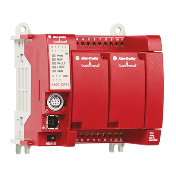
- Page 1 Wiring Diagram Guardmaster Configurable Safety Relay Catalog Number 440C-CR30-22BBB...
- Page 2 Arc Flash. Arc Flash will cause severe injury or death. Wear proper Personal Protective Equipment (PPE). Follow ALL Regulatory requirements for safe work practices and for Personal Protective Equipment (PPE). Allen-Bradley, Connected Components Workbench, Control Tower, Guardmaster, GuardShield, Lifeline, PHOTOSWITCH, PowerFlex, Rockwell Automation, Rockwell Software, SensaGuard, Trojan, and Zero-Force Touch Buttons are trademarks of Rockwell Automation, Inc....
-
Page 3: Table Of Contents
Table of Contents Preface Additional Resources ..........7 Chapter 1 Cat 1 Stop with Guardlocking Product Overview . - Page 4 Table of Contents Chapter 5 Muting 2-Sensor L-Type Product Overview ..........27 Machine Layout .
- Page 5 Table of Contents Chapter 9 Lifeline Cable Pull Product Overview ..........49 Schematic .
- Page 6 Table of Contents Notes: Rockwell Automation Publication 440C-WD001C-EN-P - June 2015...
-
Page 7: Additional Resources
Provides declarations of conformity, certificates, and other certification details. You can view or download publications at http:/www.rockwellautomation.com/literature/. To order paper copies of technical documentation, contact your local Allen-Bradley® distributor or Rockwell Automation sales representative. Rockwell Automation Publication 440C-WD001C-EN-P - June 2015... - Page 8 Preface Notes: Rockwell Automation Publication 440C-WD001C-EN-P - June 2015...
-
Page 9: Product Overview
Chapter Cat 1 Stop with Guardlocking Interlock (TLS-ZR or 440G-LZ) This example application shows how to configure the CR30 safety relay for a Guardlocking application that requires a Stop Category 1 function. A TLS-ZR guardlocking interlock, which has Output Signal Switching Device (OSSD) outputs, locks a guard to help prevent full body access to the hazard. -
Page 10: Schematic
Chapter 1 Cat 1 Stop with Guardlocking Interlock (TLS-ZR or 440G-LZ) Schematic Figure 2 - Schematic +24V DC L1 L2 L3 PowerFlex Gate Reset Lock/ 1 Stop Unlock 2 Start Safety Safety Gate Brown 4 Gnd 03 04 10 11 Yellow Gate control Pink... -
Page 11: Connected Components Workbench Software
Cat 1 Stop with Guardlocking Interlock (TLS-ZR or 440G-LZ) Chapter 1 Connected Components Figure 3 - Connected Components Workbench Example Workbench Software Circuit Status The gate switch is closed and locked. The safety signals to the PF525 drive are off, and the drive is disabled. -
Page 12: Example Bill Of Materials
Chapter 1 Cat 1 Stop with Guardlocking Interlock (TLS-ZR or 440G-LZ) Example Bill of Materials Table 3 - Bill of Materials Item Product Description Guardmaster® 440C-CR30 Software Configured Safety Relay 440C-CR30-22BBB PLe SIL 3, 22 Safety I/O, embedded serial port, USB programming port, 2 plug-in slots, 24V DC 440G-TZS21UPRH Guard Locking Switch - TLS-Z GD2... -
Page 13: Product Overview
Chapter Cat 1 Stop with GuardShield Light Curtain, T-15 Interlock, E-Stop, and PowerFlex 525 This example application shows how to configure the CR30 safety relay for a guarding application that requires a Stop Category 1 function. A light curtain is used where an operator frequently accesses the hazard area. A mechanical tongue interlock switch is mounted on a gate where infrequent access to the hazard. -
Page 14: Schematic
Chapter 2 Cat 1 Stop with GuardShield Light Curtain, T-15 Interlock, E-Stop, and PowerFlex 525 Schematic Figure 5 - Schematic +24V DC L1 L2 L3 PowerFlex 1 Stop Transmitter Receiver 2 Start Brown Brown Pink Grey Blue 4 Gnd 03 04 10 11 Blue Green... -
Page 15: Connected Components Workbench Software
Cat 1 Stop with GuardShield Light Curtain, T-15 Interlock, E-Stop, and PowerFlex 525 Chapter 2 Connected Components Figure 6 - Connected Components Workbench Example Workbench Software Circuit Status The light curtain is clear. The gate switch is closed. The E-stop is reset. The CR30 safety outputs at terminal 17, 18, and 19 are ON. -
Page 16: Example Bill Of Materials
Chapter 2 Cat 1 Stop with GuardShield Light Curtain, T-15 Interlock, E-Stop, and PowerFlex 525 Example Bill of Materials Table 6 - Bill of Materials Item Product Description Guardmaster 440C-CR30 Software Configured Safety Relay 440C-CR30-22BBB PLe SIL 3, 22 Safety I/O, embedded serial port, USB programming port, 2 plug-in slots, 24V DC 440L-P4K1760YD GuardShield™... -
Page 17: Product Overview
Chapter Safety Mats - Two Zones This application demonstrates two zones using safety mats and E-stop push buttons. Each zone is controlled by a safety mat and an E-stop push button. In this example, a sequential manufacturing process has two zones. If an operator enters the first zone, that zone stops while the second zone continues to function. -
Page 18: Schematic
Chapter 3 Safety Mats - Two Zones Schematic Figure 8 - Schematic Zone 1 Zone 2 + 24V DC E-Stop E-Stop L1 L2 L3 L1 L2 L3 Reset Reset 03 04 10 11 I-00 I-01 +24DC O-00 O-01 CR30 440C-CR30-22BBB 2080-IQ4OB4 12 13 14 20 21... -
Page 19: Connected Components Workbench Software
Safety Mats - Two Zones Chapter 3 Connected Components Figure 9 - Connected Components Workbench Example Workbench Software Rockwell Automation Publication 440C-WD001C-EN-P - June 2015... -
Page 20: Circuit Status
Chapter 3 Safety Mats - Two Zones Circuit Status No presence is sensed on both mat systems. All four contactors are off, and both motors (hazards) are off. The system is ready for reset. Operational Sequence Press Reset 1 to enable the start of Zone 1. Press Reset to enable the start of Zone 2. -
Page 21: Product Overview
Chapter Enabling Switch (GripSwitch) with Jog Function The GripSwitch is a hold-to-run enabling device. While holding the GripSwitch in the center (enabled) position, the operator then presses and holds the jog switch to operate the PowerFlex drive for a specified duration. This example requires a two-position selector switch. -
Page 22: Schematic
Chapter 4 Enabling Switch (GripSwitch) with Jog Function Schematic Figure 11 - Schematic +24V DC GripSwitch Gate Switch L1 L2 L3 Grey PowerFlex Pink 1 Stop 2 Start 4 Gnd 7 Clear Fault 8 Jog Gate control 03 04 10 11 power supply GripSwitch CR30... -
Page 23: Connected Components Workbench Software
Enabling Switch (GripSwitch) with Jog Function Chapter 4 Connected Components Figure 12 - Connected Components Workbench Example Workbench Software Logic Level B1 block is an XOR, rather than a simple OR. The Selector switch chooses either the gate interlock switch or GripSwitch. If a short circuit to 24V occurs on terminal 5, and the gate closed behind the operator, the GripSwitch would be bypassed if the simple OR block were used. -
Page 24: Operational Sequence
Chapter 4 Enabling Switch (GripSwitch) with Jog Function Operational Sequence Table 8 - Operational Sequence Action Taken Results 1. Press the drive Stop button. This clears faults in the drive. Fault F059 may be present, due to its safety inputs being off. 2. -
Page 25: Safety Rating
Enabling Switch (GripSwitch) with Jog Function Chapter 4 Safety Rating This application has four distinct safety-related functions: 1. Interlock -> Logic -> Drive The safety function that is performed by the gate switch can meet the requirements up to Cat 3 PLd per ISO13849-1, SIL CL2 per IEC62061, and SIL 2 per IEC61508. - Page 26 Chapter 4 Enabling Switch (GripSwitch) with Jog Function Notes: Rockwell Automation Publication 440C-WD001C-EN-P - June 2015...
-
Page 27: Product Overview
Chapter Muting 2-Sensor L-Type Unidirectional The CR30 safety relay has a function block that supports 2-sensor L-type muting. With this function block, the material can only move in one direction: from the hazard area to the non-hazard area. The two muting sensors are located within the hazard area, and the material must be large enough to block both sensors and the light curtain. -
Page 28: Schematic
Chapter 5 Muting 2-Sensor L-Type Unidirectional Schematic The example schematic is set up to agree with the terminals shown in the Connected Components Workbench™ software and the example bill of materials. Figure 15 - Example Schematic +24V DC Muted Muting Muting Light Curtain Sensor 1... -
Page 29: Connected Components Workbench Software
Muting 2-Sensor L-Type Unidirectional Chapter 5 Connected Components Figure 16 - Connected Components Workbench Example Workbench Software Circuit Status The circuit is ready to run. The muting sensors and the light curtain are clear. Rockwell Automation Publication 440C-WD001C-EN-P - June 2015... -
Page 30: Operational Sequence
Chapter 5 Muting 2-Sensor L-Type Unidirectional Operational Sequence The muting sensors and the light curtain participate in the sequence of events to achieve the muting. The material must move past the sensors and into the light curtain within the synchronization times, which are set in the Connected Components Workbench function block. -
Page 31: Example Bill Of Materials
Muting 2-Sensor L-Type Unidirectional Chapter 5 Example Bill of Materials Table 10 - Bill of Materials Item Product Description Guardmaster 440C-CR30 Software Configured Safety Relay 440C-CR30-22BBB PLe SIL 3, 22 Safety I/O, embedded serial port, USB programming port, 2 plug-in slots, 24V DC 440L-P4K1760YD GuardShield Safety Light Curtain Res 30 mm, protective height 1760 mm, 88 beams... - Page 32 Chapter 5 Muting 2-Sensor L-Type Unidirectional Notes: Rockwell Automation Publication 440C-WD001C-EN-P - June 2015...
-
Page 33: Product Overview
Chapter Muting 2-Sensor T-Type Bidirectional The CR30 safety relay has a function block that supports two-sensor T-type muting. With this function block, the material can only move in either direction: from the hazard area to the non-hazard area or reverse. The two muting sensors are arranged so that their beams form an “X”... -
Page 34: Machine Layout
Chapter 6 Muting 2-Sensor T-Type Bidirectional Machine Layout The material can flow in either direction: to the hazard area from the non-hazard area or reverse. The shape of the material must be such that it blocks both muting sensors before it blocks the light curtain. The order in which the muting sensors are blocked is not critical, but the synchronization time (time between blocking one sensor and the other sensor) must be met. -
Page 35: Connected Components Workbench Software
Muting 2-Sensor T-Type Bidirectional Chapter 6 Connected Components Figure 21 - Connected Components Workbench Example Workbench Software Circuit Status The circuit is ready to run. The muting sensors and the light curtain are clear. Rockwell Automation Publication 440C-WD001C-EN-P - June 2015... -
Page 36: Operational Sequence
Chapter 6 Muting 2-Sensor T-Type Bidirectional Operational Sequence The muting sensors and the light curtain participate in the sequence of events to achieve the muting. The material must move past the sensors and into the light curtain within the synchronization times, which are set in the Connected Components Workbench function block. -
Page 37: Example Bill Of Materials
Muting 2-Sensor T-Type Bidirectional Chapter 6 Example Bill of Materials Table 11 - Bill of Materials Item Product Description Guardmaster 440C-CR30 Software Configured Safety Relay 440C-CR30-22BBB PLe SIL 3, 22 Safety I/O, embedded serial port, USB programming port, 2 plug-in slots, 24V DC 440L-P4K1760YD GuardShield Safety Light Curtain Res 30 mm, protective height 1760 mm, 88 beams... - Page 38 Chapter 6 Muting 2-Sensor T-Type Bidirectional Notes: Rockwell Automation Publication 440C-WD001C-EN-P - June 2015...
-
Page 39: Product Overview
Chapter Muting 4-sensor T-type Bidirectional The CR30 safety relay has a function block that supports 4-sensor T-type muting. With this function block, the material can only move in either direction: from the hazard area to the non-hazard area or reverse. The four muting sensors are arranged so that their beams cross orthogonally across the conveyor: two inside the hazard area and two outside the hazard area. -
Page 40: Machine Layout
Chapter 7 Muting 4-sensor T-type Bidirectional Machine Layout The material can flow in either direction: to the hazard area from the non-hazard area or reverse. The shape of the material must be such that it blocks both muting sensors before it blocks the light curtain. The order in which the muting sensors are blocked is not critical, but the synchronization time (time between blocking one sensor and the other sensor) must be met. -
Page 41: Connected Components Workbench Software
Muting 4-sensor T-type Bidirectional Chapter 7 Connected Components Figure 26 - Connected Components Workbench Example Workbench Software Circuit Status The circuit is ready to run. The muting sensors and the light curtain are clear. Rockwell Automation Publication 440C-WD001C-EN-P - June 2015... -
Page 42: Operational Sequence
Chapter 7 Muting 4-sensor T-type Bidirectional Operational Sequence The muting sensors and the light curtain participate in the sequence of events to achieve the muting. The material must move past the sensors and into the light curtain within the synchronization times, which are set in the Connected Components Workbench function block. -
Page 43: Example Bill Of Materials
Muting 4-sensor T-type Bidirectional Chapter 7 Example Bill of Materials Table 12 - Bill of Materials Item Product Description Guardmaster 440C-CR30 Software Configured Safety Relay 440C-CR30-22BBB PLe SIL 3, 22 Safety I/O, embedded serial port, USB programming port, 2 plug-in slots, 24V DC 440L-P4K1760YD GuardShield Safety Light Curtain Res 30 mm, protective height 1760 mm, 88 beams... - Page 44 Chapter 7 Muting 4-sensor T-type Bidirectional Notes: Rockwell Automation Publication 440C-WD001C-EN-P - June 2015...
-
Page 45: Product Overview
Chapter Single-wire Safety This example application focuses on the single-wire safety (SWS) feature built into the CR30 safety relay. The CR30 safety relay has two input terminals that can be configured to use single wire safety and two output terminals that can be configured to use single wire safety. -
Page 46: Schematic
Chapter 8 Single-wire Safety Schematic A partial schematic is shown in Figure 29 to highlight the SWS connections. Figure 29 - Schematic +24V DC Reset 03 04 10 11 CR30 Reset 12 13 14 20 21 S11 S21 RESET Sensa- Sensa- Guard Guard... -
Page 47: Connected Components Workbench Software
Single-wire Safety Chapter 8 Connected Components The Connected Components Workbench software shows two safety functions: Workbench Software • SWS In #1 & Gate #1 → SWS Out #1 (Immediate OFF) • SWS In #2 & Gate #2 → SWS Out #2 (Delayed OFF) Figure 30 - Connected Components Workbench Example Circuit Status The safety gates are closed and the SWS safety inputs are active. -
Page 48: Operational Sequence
Chapter 8 Single-wire Safety Operational Sequence Press Reset #1 to activated SWS output #1 (terminal 20). Press Reset #2 to activate SWS output #2 (terminal 21). Deactivating SWS In #1 on terminal 10 or opening Gate #1 turns off SWS output #1. -
Page 49: Rockwell Automation Publication 440C-Wd001C-En-P - June
Chapter Lifeline Cable Pull Lifeline™ cable pull switches are emergency stop devices with mechanical contacts. The application uses pulse testing to check for potential short-circuits to 24V, ground and across channels. Manual monitored reset prevents the outputs from turning ON when Lifeline switches are reset. Product Overview Figure 31 - Overview Rockwell Automation Publication 440C-WD001C-EN-P - June 2015... -
Page 50: Schematic
Chapter 9 Lifeline Cable Pull Schematic Figure 32 - Schematic +24V DC Reset 11 21 03 04 10 11 Cable CR30 12 22 12 13 14 20 21 24V DC Com Connected Components The Lifeline 4 switches are emergency stop devices. The emergency stop function blocks are ANDed as both must be closed for the Immediate Safety Output to Workbench Software turn ON. -
Page 51: Product Overview
Chapter Two-hand Control This application example shows the setup for two separate 2-hand controls each that meets ISO 13851 Type IIIC. One uses mechanical outputs, and the other uses OSSD outputs. Each of the 800Z Zero-Force Touch Buttons™ has a normally open and normally closed contact. -
Page 52: Connected Components Workbench Software
Chapter 10 Two-hand Control Connected Components Figure 35 - Connected Components Workbench Example Workbench Software Circuit Status In both circuits, there are no hands on the buttons. All four output contactors are off. Operational Sequence The two circuits work independently. You must simultaneously press S1 and S2 (or S3 and S4) to turn on contactors K1 and K2 (or K3 and K4), where simultaneously means within a half second of each other. -
Page 53: Example Bill Of Materials
Two-hand Control Chapter 10 Example Bill of Materials Table 15 - Bill of Materials Item Product Description Guardmaster 440C-CR30 Software Configured Safety Relay 440C-CR30-22BBB PLe SIL 3, 22 Safety I/O, embedded serial port, USB programming port, 2 plug-in slots, 24V DC 800Z-GL3Q5 30.5 mm Type 4/4X/13 IP66 Zero-Force Momentary General Purpose Touch Button... - Page 54 Chapter 10 Two-hand Control Notes: Rockwell Automation Publication 440C-WD001C-EN-P - June 2015...
-
Page 55: Product Overview
Chapter Multifunction Access Box This application example shows the setup of a multifunction access box (MAB). The MAB is a guardlocking interlock with additional features to facilitate access to a hazard area. In this example, you press a button to request access. The safety system shuts down the hazard and then unlocks the door. -
Page 56: Schematic
Chapter 11 Multifunction Access Box Schematic Figure 37 - Schematic + 24V DC Safety Gate UB UA 2.3 2.4 Closed & Unlock Locked L1 L2 L3 Close Reset 03 04 10 11 Open CR30 12 13 14 20 21 K1 K2 24V DC Com The signal from MP17 is fed back into the CR30 safety relay at terminal 9. - Page 57 Multifunction Access Box Chapter 11 Connected Components Figure 38 - Connected Components Workbench Example Workbench Software Rockwell Automation Publication 440C-WD001C-EN-P - June 2015...
-
Page 58: Circuit Status
Chapter 11 Multifunction Access Box Circuit Status The gate is closed and locked. The E-stop is released. The 100S contactors are de-energized, and the motor is OFF. On the MAB, the reset indicator is ON, which indicates that the reset button must be pressed. Operational Sequence 1. -
Page 59: Product Overview
Chapter Dynamic Feedback This application example shows how to configure the CR30 safety relay to monitor the feedback contact of an output device dynamically. With safety rated relays and contactors, the normally closed feedback contacts are either positively guided, mechanically linked, or mirrored. These features are designed to help ensure that the normally closed contact moves with the normally open contacts. -
Page 60: Schematic
Chapter 12 Dynamic Feedback Schematic Figure 40 - Schematic +24V DC Reset Potential Feedback Fault Feedback Feedback OK Contacts D1 D2 D3 E-stop 03 04 10 11 CR30 12 13 14 20 21 Poppet Valve Feedback Closed * 24V DC Com One or more feedback circuits are closed The feedback indicator is ON when the E-stop is pressed and the outputs (D1…D4) are OFF. - Page 61 Dynamic Feedback Chapter 12 Connected Components Figure 41 - Connected Components Workbench Example Workbench Software Rockwell Automation Publication 440C-WD001C-EN-P - June 2015...
-
Page 62: Circuit Status
Chapter 12 Dynamic Feedback Circuit Status The E-stop is released and all output devices (D1…D4) are OFF. The Feedback Closed indicator is ON. Operational Sequence 1. Press the Reset button. All four output devices D1…D4 turn ON and the Feedback Closed indicator turns OFF. - Page 64 Rockwell Automation Support Rockwell Automation provides technical information on the Web to assist you in using its products. http://www.rockwellautomation.com/support you can find technical and application notes, sample code, and links to software service packs. You can also visit our Support Center at https://rockwellautomation.custhelp.com/ for software updates, support chats and forums, technical information, FAQs, and to sign up for product notification updates.