
Related Manuals for Allen-Bradley E100


Summary of Contents for Allen-Bradley E100
- Page 1 User Manual Original Instructions E100 Electronic Overload Relay Catalog Numbers 193, 592...
- Page 2 Important User Information Read this document and the documents listed in the additional resources section about installation, configuration, and operation of this equipment before you install, configure, operate, or maintain this product. Users are required to familiarize themselves with installation and wiring instructions in addition to requirements of all applicable codes, laws, and standards.
-
Page 3: Table Of Contents
Appendix A E100 Wiring Configurations........19... - Page 4 Table of Contents Notes: Rockwell Automation Publication 193-UM013B-EN-P - December 2019...
-
Page 5: Preface
Codes table. Throughout this publication, we also refer to the E100 Electronic Overload Terminology Relay as the E100 overload relay and E100 relay. These terms are interchangeable. These documents contain additional information concerning related products Additional Resources from Rockwell Automation. - Page 6 Preface Notes: Rockwell Automation Publication 193-UM013B-EN-P - December 2019...
-
Page 7: Description
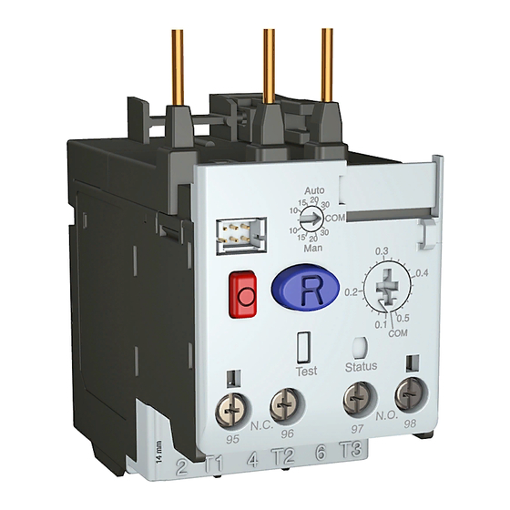
Chapter Product Overview This chapter provides an overview of the E100™ Electronic Overload Relay. The E100 Electronic Overload Relay is the newest technology for overload Description protection, and supports both single- and three-phase operation in a single component. The device is split between two offerings: a Basic (Cat. No. 193-1EE) and Advanced (Cat. - Page 8 Chapter 1 Product Overview Notes: Rockwell Automation Publication 193-UM013B-EN-P - December 2019...
-
Page 9: Chapter 2 Before You Begin
Trip Current and Trip Class. This chapter also describes the accessory modules that are available for the Advanced (193/592-1EF) E100 relay. Before you configure the E100 relay, you must install it onto a contactor or DIN Before You Begin Rail, or mount it on a panel. See... -
Page 10: Set The Trip Current
Chapter 2 System Operation and Configuration Set the Trip Current When you set the trip current, you must consider the motor service factor and FLA. You can find this information on the motor nameplate, as shown in Table 1 Table Table 1 - Service Factor/Motor FLA Dial Settings Service Factor Service Factor... -
Page 11: Configure Accessory Modules
The Cat. No. 193-1EGJ E100 Universal Protection expansion module adds Ground fault and Jam protection to the Advanced version (193/592-1EF) of the E100 relay. The add-on module lets you select the jam current level, jam trip delay, and ground fault level. -
Page 12: Indication Display Module
The Cat. No. 193-1ERR Electronic Reset and Indication Display Module lets you use the Cat. No. 193-ERID and 193-ERIDN Remote Indication and Display module with your Advanced version (193/592-1EF) of the E100 relay. Figure 4 - Cat. No. 193-1ERR Electronic Reset and Indication Display Module... -
Page 13: Cat. No. 193-Erid Or 193-1Eridn Remote
Module The remote indication and display modules let you view the status of the E100 relay from the front of a panel. Cat. No. 193-ERID also features a reset button. The light-emitting diode (LED) status indicators notify you of the status of the overload relay. - Page 14 Chapter 2 System Operation and Configuration Notes: Rockwell Automation Publication 193-UM013B-EN-P - December 2019...
-
Page 15: E100 Electronic Overload Relay
E100 Electronic Overload All E100 relay units include a trip indicator window on the front of the unit labeled “Status”. If the red indicator is not visible, the overload relay is not Relay tripped. -
Page 16: Remote Indication Display
Chapter 3 Troubleshooting Table 3 - 193-1EGJ and 193-1ERR Remote Indication and Display Module Fault/Status Codes Status Indicator Solid/Flashing Description Solution Color Flashing Module powered — Green Solid Module powered and motor current present — Amber Flashing Warning Flashing Fault detected and overload relay tripped •... - Page 17 Test Trip (1) An Overload warning occurs when the E100 overload reaches 90% thermal capacity utilization (TCU ). The overload trips at 100% TCU. (2) Phase Loss warning is active if the overload detects a Phase Loss condition. The warning is maintained for 3 seconds before a Phase Loss Trip occurs.
- Page 18 Chapter 3 Troubleshooting Notes: Rockwell Automation Publication 193-UM013B-EN-P - December 2019...
-
Page 19: E100 Wiring Configurations
Appendix Wiring Diagrams The following pages illustrate various wiring configurations for the E100™ Electronic E100 Wiring Configurations Overload Relay. Figure 8 - 3-Phase, Full-voltage Direct-on-line Starter, NEMA Symbology Short-circuit Protection Device Connection must be fitted by the user Figure 9 - 3-Phase, Full-voltage Direct-on-line Starter, IEC Symbology... - Page 20 Figure 11 - 1-Phase, Full-voltage Direct-on-line Starter, IEC Symbology Connection must be fitted by the user Short-circuit Protection Device Connection must be fitted by the user Figure 12 - E100 Overload Relay with External Current Transformer L1/1 L2/3 L3/5 L1/1 L2/3 L3/5 H1(Dot)
- Page 21 Notes:...
- Page 22 How Are We Doing? form at rok.auto/docfeedback. Rockwell Automation maintains current product environmental information on its website at rok.auto/pec. Allen-Bradley, E100, Rockwell Automation, and Rockwell Software are trademarks of Rockwell Automation, Inc. Trademarks not belonging to Rockwell Automation are property of their respective companies.