Siemens SIMATIC S7-300 Manual
Fm 354 servo drive positioning module
Hide thumbs
Also See for SIMATIC S7-300:
- Manual (676 pages) ,
- Reference manual (574 pages) ,
- Installation and operating manual (356 pages)

Related Manuals for Siemens SIMATIC S7-300


Summary of Contents for Siemens SIMATIC S7-300
- Page 1 SIMATIC S7-300 FM 354 Servo Drive Positioning Module Manual 04.97 Edition This manual is intended to accompany the configuration package, Order No.: 6ES7 354-1 AH01-7AG0.
- Page 3 Preface, Contents User Information Product Summary Basic Principles of Positioning SIMATIC S7 Installing and Removing the FM 354 FM 354 Servo Drive Positioning Wiring the FM 354 Module Defining Parameters of the FM 354 Manual Programming the FM 354 Starting up the FM 354 Human-machine Interface for the OP 07/OP 17 Reference Information...
- Page 4 Trademarks SIMATIC and SINEC are registered trademarks of SIEMENS AG. Third parties using for their own purposes any other names in this document which refer to trademarks might infringe upon the rights of the trademark owners. Copyright...
-
Page 5: Describes The Connection And Wiring Of Drives, Encoders And Digital Input
Preface Purpose of this This manual contains all information about the FM 354 module: document Hardware and functions Parameter definition Human-machine interface S7 function blocks Safe setup Information blocks The following information blocks describe the purpose and uses of this in this manual manual: Product overview of the module (Chapter 1) - Page 6 List of abbreviations and index for looking up information. User requirements The present manual describes the hardware and functions of the FM 354 To set up, program and start up a SIMATIC S7-300 with the FM 354, you will need a knowledge of: The SIMATIC S7 Installation manual S7-400/M7–400 Programmable Controller, Hardware...
- Page 7 Preface CE marking Our products are in compliance with the EU Guideline 89/336/EEC “Electro- magnetic Compatibility” and the harmonized European standards (EN) which it embodies. The EC Declaration of Conformity in accordance with Article 10 of the EU Guideline referenced above is contained in this manual (see Chapter B). Contact partners If you should encounter any problems using this manual, or if you have any questions, please contact the office specified on the query form at the end of...
- Page 8 Preface FM 354 Servo Drive Positioning Module...
-
Page 9: Table Of Contents
Contents Product Summary ............The FM 354 in the S7-300 programmable controller . - Page 10 Contents FC RD_COM (FC 3) – Process read jobs cyclically ....6-13 Reading diagnostic information ........6-17 6.4.1 FC DIAG_RD (FC 4) –...
- Page 11 Contents 9.3.6 Set actual value on–the–fly (job no. 14) ......9-47 9.3.7 Request application data (job no.
- Page 12 Contents Figures Multi–rack configuration of a SIMATIC S7-300 with FM 354 (example) System overview (schematic) ........
- Page 13 Contents Operating mode selection, PIC75 ........8-11 Teach In PIC735 .
- Page 14 Contents DB structure – traversing programs ....... . . 5-20 Menus of “Parameterize FM 354”...
-
Page 15: Product Summary
The FM 354 is a high-performance module for tasks in servo-controlled posi- tioning. The module works autonomously and is controlled by way of the user pro- gram in the SIMATIC S7-300 system. It can operate rotary and linear axes by servo or open-loop control with actu- al-value tracking. -
Page 16: Compatibility List For Use Of The Fm 354 With S7-300 Cpus And Ops
Product Summary Compatibility list Please note the following compatibility specifications for the various product releases/order numbers when using the FM 354 with CPUs of the S7-300 sys- tem and with OPs. Table 1-1 Compatibility list for use of the FM 354 with S7-300 CPUs and Modules are compatible with each other... -
Page 17: The Fm 354 In The S7-300 Programmable Controller
Product Summary The FM 354 in the S7-300 programmable controller How is the FM 354 The FM 354 is designed as a function module of the SIMATIC S7-300 con- linked up with the troller. S7-300? The S7-300 programmable controller consists of a CPU and a variety of pe- ripheral modules mounted on a mounting rail. -
Page 18: Multi-Rack Configuration Of A Simatic S7-300 With Fm 354 (Example)
Product Summary Multi–rack A SIMATIC S7-300 CPU may run up to four racks with as many as eight bus configurations stations each (see Figure 1-1). Programming device Operator panel Backplane bus Rack 3 dig./anal. dig./anal. dig./anal. dig./anal. dig./anal. dig./anal. 24 V Rack 2 dig./anal. - Page 19 A positioning controller using the FM 354 consists of a variety of individual tem components components. which are shown in Figure 1-2. Operator panel (OP) Your programming device (PG) (e.g. OP 05) Configuration package DIN rail SIMATIC S7-300 SM SM FM 354 Power section e.g. SIMODRIVE e.g. touch 611-A probe Encoders Motor e.g.
-
Page 20: Components Of A Positioning Controller
Product Summary Components The most important components and their functions are listed in Table 1-2. Table 1-2 Components of a positioning controller Component Function DIN rail ... the module mounting rack for the S7-300. FM 354 ... the positioning module. It is controlled by the S7-300 CPU. -
Page 21: Data Storage Concept
Product Summary System overview The following figure gives you an overview of the data storage concept. of data handling FM 354 Module data Load memory Module data Diagnostic data P bus User program, in- cluding FCs User DBx Diagnostic/ process inter- Online data rupt DBx pa-... -
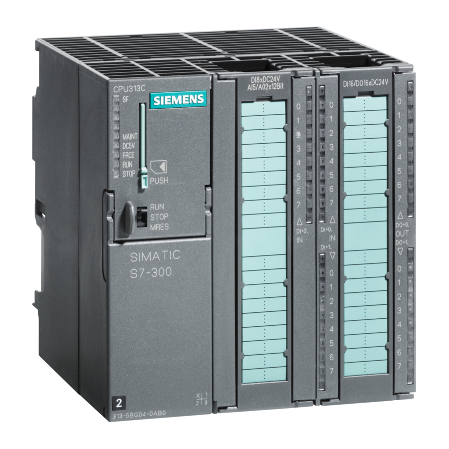
Page 22: Module Description
Product Summary Module description View of the FM 354 Figure 1-4 shows the FM 354 module, its interfaces and front-panel elements (including fault and status displays). DIN rail Module name plate: FM 354 F.SERVO MOTOR Bus connector – SIMATIC port Front door Labeling plate (flips open) -
Page 23: Status And Error Displays
Product Summary Ports A description of the ports is provided in Table 1-3 . Table 1-3 Ports Ports Description Bus connector – Back connector to continue the S7 LAN from module to SIMATIC port module Drive port 9-pin male sub-D connector (X2) to connect the drive unit Measurement system port 15-pin female sub-D connector (X3) to connect the en- coder I/O port... -
Page 24: Type Plate Of The Fm
Product Summary Type plate of the Figure 1-5 describes all the information contained in the type plate of the FM FM 354 354. SIEMENS SVP JM123456 Made in Germany Product status Marks and approvals Module identifier Order number Fig. 1-5... -
Page 25: Overview Of Module Functions
Product Summary Overview of module functions Summary The FM 354 module performs the following functions: Mode control Actual-value capture Servo position control Digital inputs and outputs Settings and functions that do not depend on operating mode Software limit switches Process interrupts Block sequence control Diagnostics and troubleshooting Data storage on the FM 354... - Page 26 Product Summary Digital inputs/out- Four digital inputs and four outputs can be used as specified by the user. puts You might connect: Reference-point switches Switches for external starting Touch probes Position reached, Stop (“PEH”) Forward/backward rotation The switching function is assigned to a given I/O number by way of the ma- chine data.
-
Page 27: Basic Principles Of Positioning
Basic Principles of Positioning What is position- Positioning means moving a load to a defined position within a defined time, ing? taking all influencing forces and torques into account. Position A Position B F = driving force x = distance to be traversed s = path Fig. -
Page 28: Setup Of Servo-Controlled Positioning, Example
Basic Principles of Positioning Structure of a Figure 2-2 shows the structure of a position control circuit with the FM 354. positioning circuit Power grid FM 354 EMERG. STOP Reference position Power section Safety e.g., SIMO- device DRIVE 611-A Parame- Actual terize position... -
Page 29: Installing And Removing The Fm 354
Installing and Removing the FM 354 Overview The FM 354 is intended for installation as an I/O module in the SIMATIC S7-300 programmable logic controller. Important safety There are important rules which you must follow when integrating an FM rules 354 in the S7-300 PLC in a plant or system. -
Page 30: Installing The Fm
Installing and Removing the FM 354 Installing the FM 354 Rules No particular protective measures (EGB Guidelines) are necessary for the installation of the FM 354. Warning Install the FM 354 only after all power to the S7-300 has been turned OFF. Tools required A 4.5 mm (.18 inch) screwdriver. -
Page 31: Removing The Fm 354
Installing and Removing the FM 354 Removing the FM 354 Rules No particular protective measures (EGB Guidelines) are necessary for the removal of the FM 354. Warning Remove the FM 354 only after all power to the S7-300 has been turned OFF. Tools required A 4.5 mm (.18 inch) screwdriver. -
Page 32: Module Replacement
Installing and Removing the FM 354 Module replacement Overview If a defective FM 354 has to be replaced, and no programming device/PC is available for parameterization, or the module is to be replaced while the sys- tem is switched on, please note the following start–up requirements (CPU, FM): An SDB 1 000 should be generated in order to complete the startup... -
Page 33: Wiring The Fm 354
Wiring the FM 354 Safety rules In order to ensure the safe operation of your plant, you should introduce the following additional measures, and adjust them appropriately to your sys- tem’s conditions: An EMERGENCY STOP concept meeting appropriate safety regulations (e.g. -
Page 34: Wiring An Fm 354
Wiring the FM 354 Wiring an FM 354 Summary Figure 4-1 shows how the individual components of the positioning controller with FM 354 are linked together. SIMATIC S7-300 SIEMENS Front connector External 24 V power supply FM 354 MPI connecting cable Setpoint cable Dig. -
Page 35: Connecting Cables For A Positioning Controller With Fm
Wiring the FM 354 Connecting cables Table 4-1 lists the connecting cables for a positioning controller with the FM 354. Table 4-1 Connecting cables for a positioning controller with FM 354 Type Order No. Description MPI connecting see Catalog ST 70, Order No. Connection between OP, cable E86060-K4670-A101-A2... -
Page 36: Description Of The Drive Interface
Wiring the FM 354 Description of the drive interface Connector for the Power sections with an analog interface ( 10 V) can be connected to the drive unit 9–pin sub–D X2 connector of the FM 354. The FM 354 also provides an enable signal. Connector location Figure 4-2 shows the installation position and identification of the plug on the module. -
Page 37: Electrical Parameters Of The Setpoint Signal
Wiring the FM 354 Signals One voltage signal and one enable signal are provided. SETPOINT (SW) An analog voltage signal in the range 10 V, for output of an rpm set- point. REFERENCE SIGNAL (BS) A reference potential (analog ground) for the setpoint signal, internally connected with the logic ground. -
Page 38: Connecting The Drive Unit
The cable set supplied as an accessory offers excellent immunity against interference. Connecting cable FM 354 Drive unit, e.g. SIMODRIVE 611-A SIEMENS SIMODRIVE Fig. 4-3 Connecting a SIMODRIVE 611-A drive unit FM 354 Servo Drive Positioning Module... -
Page 39: Location Of The X3 Connector
Wiring the FM 354 Procedure to con- Connect the drive unit as follows: nect the connect- 1. Wire the free cable end of the connecting cable to the terminals of the ing cable drive unit. (The terminal identifiers on the cable ends indicate the proper terminals for SIMODRIVE units.) 2. -
Page 40: Pinout Of The X3 Connector
Wiring the FM 354 Connector pinout Identifier: ENCODER X3 Type: 15-pin female sub-D plug connector Table 4-5 Pinout of the X3 connector Encoders Encoders type type type type Incremental Absolute Incremental Absolute MEXT CLS_N P5EXT P24EXT P5EXT DATA_N MEXT DATA open Signal names Maintenance signal negated (incremental encoder) -
Page 41: Electrical Parameters Of Encoder Power Supply
Wiring the FM 354 Encoder Both encoders that can be connected directly and EXEs must meet the fol- characteristics lowing requirements: Incremental Encoders Transfer procedure: Differential transfer with 5 V rectangular signals (such as RS422 standard) Output signals: Track A as true and negated signal (U Track B as true and negated signal (U Zero signal N as true and negated signal Maximum output frequency: 1 MHz... -
Page 42: Maximum Cable Length As A Function Of Encoder Power Supply
The maximum cable length depends on the specifications of the encoder to encoder power supply, and on the transfer frequency. For trouble-free operation, you should not exceed the following values when using SIEMENS cable sets: Table 4-7 Maximum cable length as a function of encoder power sup-... -
Page 43: Connecting The Encoders
Wiring the FM 354 Connecting the encoders To connect the Please note: connecting cables Note Use only shielded cables. The shielding must be connected to the metallic or metallized connector jacket. The cable sets supplied as an accessory offer excellent immunity from inter- ference, as well as cross-sections large enough for the power supply to the encoders. - Page 44 Wiring the FM 354 Procedure for To connect the encoders: connecting 1. Connect the connecting cables to the encoders. encoders For absolute encoders (SSI) it may be necessary to cut and add connectors to the cable (end of the cable to the encoder) according to the manufactur- er’s instructions.
-
Page 45: Location Of X1 Connector
Wiring the FM 354 Description of the I/O interface Front connector Four digital input/output modules and the standby signal (controller message) may be connected to the 20-pin front connector X1 with its single-wire termi- nal. Location of Figure 4-6 shows the front connector in position to be wired, and the labeling connector on the inside of the front door. -
Page 46: Pinout Of The X1 Connector
Wiring the FM 354 Connector pinout Connector identifier: Connector type: 20-pin S7 front connector for single-wire terminal Table 4-9 Pinout of the X1 connector Name Type Name Type open open open open open open open open RM_P RM_N Signal names DI1...4 Digital input 1...4 DQ1...4... -
Page 47: Electrical Parameters Of Digital Inputs
Wiring the FM 354 Table 4-10 Electrical parameters of digital inputs Parameters Value Unit Notes 1 signal, voltage range 11...30 1 signal, power consumption 6...15 0 signal, voltage range –3...5 or input open µs Signal delay 0 µs Signal delay 1 “Controller mes- The standby signal of the drive power section (controller message) can be sage”... -
Page 48: Actuation Of The Input Controller Message, Power Supply From The Control
Wiring the FM 354 Power from the Figure 4-7 shows examples of how to power the standby signal from the con- open-loop control troller (e.g. SIMODRIVE 611 drive unit). Actuation of input controller message by high-side switch or relay contact Drive unit High-side switch or relay contact... -
Page 49: Electrical Parameters Of Digital Outputs
Wiring the FM 354 4 digital outputs All outputs have equal priority. Switching functions are allocated to an output (DO1...4) number by way of machine data. These four outputs are intended for wiring of application-specific signals. Possible uses include: Position reached and stopped Switching function M command Forward/backward rotation See Section 5.3.1 for further applications. -
Page 50: Wiring Up The Front Connector
Wiring the FM 354 Wiring up the front connector Wiring the front Figure 4-9 shows you how to install the conductors on the front connector connector and how to relieve the strain with the shield connection element. ENCODER X3 DC5V DIAG –... - Page 51 Wiring the FM 354 Tools required A 3.5 mm (.13 inches) screwdriver or power screwdriver. Procedure for To wire the terminal strip: wiring the front 1. Strip 6 mm (.23 inches) of insulation from the cable; apply ferrules, connector if any. 2.
- Page 52 Wiring the FM 354 FM 354 Servo Drive Positioning Module 4-20...
-
Page 53: Overview Of Parameterization
Defining Parameters of the FM 354 Summary This chapter gives you an overview of how to define the parameters of the FM 354 with the “Parameterize FM 354” tool. S7-300 FM 354 P bus Data blocks (DB) User DB-MD data block Online (editing in the DB-SM Target system menu... -
Page 54: Getting Started With "Parameterize Fm 354
SIEMENS\STEP7\S7FLAG – Function blocks: SIEMENS\STEP7\S7LIBS\FMST_SRV – User interface for OPs: SIEMENS\STEP7\EXAMPLES\S7OP_BSP – Example applications: SIEMENS\STEP7\EXAMPLE1\FMSTSVEX Note If you chose a directory other than SIEMENS/STEP7 when you installed STEP 7, this directory is entered instead. FM 354 Servo Drive Positioning Module... - Page 55 Defining Parameters of the FM 354 Getting started with “Parameterize FM 354” Prerequisites You have installed the software on your programming device/PC, as de- scribed in Section 5.1. Configuration Before you can configure your system, you must create a project in which to save the parameters.
-
Page 56: Overview Display For Parameterization
Defining Parameters of the FM 354 7. By clicking the tabs in this window (General, Addresses and Basic Pa- rameters), you can – Name the FM 354 – Change the address of the FM 354 – Configure the interrupts. Note: Further operation of the FM 354 is not possible with the CPU in the STOP state. - Page 57 Defining Parameters of the FM 354 Proceed as follows: 1. Position the mouse pointer on the top border of the window, so that it changes into an arrow. 2. Press the left mouse button, and drag the pointer downwards by moving the mouse.
-
Page 58: Data Blocks
Defining Parameters of the FM 354 Parameter data What can I You can parameterize the following data storage areas: parameterize? Machine data (MD) Increment sizes (SM) Tool offset data (TO) Traversing programs (NC) User data (user data blocks) This data is stored in data blocks (DBs) within the numerical range 1001 to 1239 (not including user data). - Page 59 Defining Parameters of the FM 354 Table 5-1 Data blocks, continued Data block Significance DB-SM Increments (DB No. = 1230) Block size (rounded in bytes) = 460 Increments serve in the “Relative incremental” operating mode as user-definable relative path distances for individual positioning. You can define from 1 to 100 increment sizes (see Section 5.3.2).
-
Page 60: User Db
Defining Parameters of the FM 354 User data block Chapter 6 describes how to generate a user data block. You can use “Parameterize FM 354” to fill the user DB with the data de- scribed in Table 5-2. The menu Target system Online editing User data allows you to select and edit your user DB. -
Page 61: Data Block Structure
Defining Parameters of the FM 354 Data block Table 5-3 gives a rough picture of data block structure. structure Table 5-3 Data block structure Addresses/Off- Comment Contents System information, not rele- DB header vant for user Information for labeling of data 0 and above User data area / structure header block within the system... -
Page 62: Entering Values For Machine Data
Defining Parameters of the FM 354 Entering values In “Parameterize FM 354” select the menu File New Machine Data to call up the following display. Fig. 5-4 Entering values for machine data Enter the machine data in the tab windows. You can also enter your values in a table by selecting View Table form. -
Page 63: Machine Data List
Defining Parameters of the FM 354 Machine data list All machine data of the FM 354 are listed in Table 5-5. Notes to the machine data list: K stands for configuration data: see Section9.3.3 E stands for user-definable machine data settings for readjustment (startup optimization) and technology;... - Page 64 Defining Parameters of the FM 354 Table 5-5 Machine data list, continued Default Data type/ Designation Value/Meaning values Unit/Comments Section 15 K Baud rate – 78,000 DWORD 9.6.1 absolute encoder 2 = 156,000 9.6.2 3 = 312,000 4 = 625,000 5 = 1,250,000 16 K Reference- –1,000,000,000...+1,000,000,000...
- Page 65 Defining Parameters of the FM 354 Table 5-5 Machine data list, continued Default Data type/ Designation Value/Meaning values Unit/Comments Section 30 E Backlash compensa- –1 000 000...+1 000 000 DINT (MSR) tion 31 E Directional reference 0 = as in search for reference DWORD of backlash (not for absolute encoders)
- Page 66 Defining Parameters of the FM 354 Table 5-5 Machine data list, continued Default Data type/ Designation Value/Meaning values Unit/Comments Section BITFIELD32 36 K Input adjustment 8 = I0 inverted 9 = I1 inverted (signal processing in- 10 = I2 inverted verted) 11 = I3 inverted 37 K Servo control signals...
- Page 67 Defining Parameters of the FM 354 Reference variables generated internally from MD: Generation of travel per encoder revolution UMWEG –32 UMWEG = MD11 + MD12 2 Generation of internal measured value factor MWFAKTOR MD10 Measured value factor MWFAKTOR = 1 MWFAKTOR = UMWEG / (4 MD13) 3, 4, 13, 14 MWFAKTOR = UMWEG / MD13...
- Page 68 Defining Parameters of the FM 354 MD13 check MD10 Increments per encoder revolution 0, 1 – 3, 4, 13, 14 x = 1, 2, 3, ... MD14 check MD10 No. of revolutions 0, 1, 3, 13 – 4, 14 x = 1, 2, 3, ... MD21, MD22 check SEAKT MD8 Permissible software limit switches...
-
Page 69: Entering Values For Incremental Dimensions
Defining Parameters of the FM 354 5.3.2 Increments DB structure Table 5-6 gives you a general view of the structure of the “Increments” data block (DB-SM). Table 5-6 DB structure – increments Byte Variable type Value Significance of the variables Comment DB header WORD... -
Page 70: Db Structure - Tool Offset Data
Defining Parameters of the FM 354 5.3.3 Tool offset data DB structure Table 5-7 gives you a general view of the structure of the “tool offset data” data block (DB-WK). Table 5-7 DB structure – tool offset data Byte Variable type Value Significance of the variables Comment... -
Page 71: Entering Values For Tool Offset Data
Defining Parameters of the FM 354 Input of values Values are input in the tool offset data menu of the “Parameterize FM 354” parameterization tool. If the additive wear value is changed online, the FM calculates the new wear parameter as an absolute value and the additive tool wear is reset to 0. Fig. - Page 72 Defining Parameters of the FM 354 5.3.4 Traversing programs DB structure Table 5-8 gives you a general view of the structure of the “traversing pro- grams” data block (DB-NC). Table 5-8 DB structure – traversing programs Byte Variable type Value Significance of the variables Comment DB header...
-
Page 73: Entry For Traversing Programs
Defining Parameters of the FM 354 Input of traversing An empty window is provided for the input of NC traversing programs. Here programs you can input your traversing program as follows: Fig. 5-7 Entry for traversing programs 1. % Program number Program name The “%”... -
Page 74: Menus Of "Parameterize Fm
Defining Parameters of the FM 354 Parameterization with “Parameterize FM 354” Entering the val- You have a variety of options for entering your parameterization data. 1. User data You can input values or select texts in a table. Select input fields with the cursor and enter the values. - Page 75 Defining Parameters of the FM 354 Table 5-9 Menus of “Parameterize FM 354”, continued Menu title or entry Shortcut Significance (with single command) Close Ctrl + F4 Closes the window of the current DB Save Ctrl + S Saves the current data block on the programming device/PC Export...
- Page 76 Defining Parameters of the FM 354 Table 5-9 Menus of “Parameterize FM 354”, continued Menu title or entry Shortcut Significance (with single command) Destination system – Transfers data and data blocks Communications – Establishes or disconnects online connection with destination system Load >...
- Page 77 Defining Parameters of the FM 354 Table 5-9 Menus of “Parameterize FM 354”, continued Menu title or entry Shortcut Significance (with single command) Extras – Settings in the data blocks Set system of measurement – Change the system of measurement in the current window –3 –...
-
Page 78: Creating Sdb
Defining Parameters of the FM 354 Storing the parameter data in SDB 1 000 Overview The FM 354 stores its parameter data internally. In order to ensure that the parameter data are available if a fault develops on the FM 354 and no programming device/PC is at hand, the data can be stored in a system data block in the CPU (SDB 1 000). -
Page 79: Displaying/Deleting Sdb
Defining Parameters of the FM 354 Display/delete SDB in the S7 Select menu File Display SDB project All SDBs for FM 354 of the project are displayed Close the win- Delete SDB? Select SDB and delete Fig. 5-9 Displaying/deleting SDB 1 000 Loading the SDB When you have created the SDB, you must load the “system data”... - Page 80 Defining Parameters of the FM 354 Deleting SDBs in To delete the SDBs in the CPU: the CPU 1. Select “Parameterize FM 354”. 2. Select menu File Display SDB. Delete the SDB(s). 3. Close “Parameterize FM 354” and in the SIMATIC Manager in Online Project select CPU\S7-Program\blocks\system data.
-
Page 81: Overview Of Programming
Programming the FM 354 Summary The present programming instructions describe the functions (FCs) that allow you to establish communications between the CPU and the FM 354 function module in the SIMATIC S7-300. S7-300 FM 354 The user DB can be... - Page 82 Programming the FM 354 Prerequisites The following prerequisites must be fulfilled in order to control the FM 354 from your user program: You have installed the software on your programming device/PC, as de- scribed in Section 5.1. The link between the programming device/PC and the S7-300 CPU must already be set up (see Figure 4-1).
-
Page 83: Overview Of Linking The Fm 354 Into The User Program
Programming the FM 354 Linking the The following figure shows you how the FM 354, the user data block (user FM 354 into the DB) and technology functions communicate. user program FM 354 OB 40 OB 82 4 bytes of OB startup information Diagnostic in- (Process (Diagnostics) - Page 84 Programming the FM 354 Chapter over- In Section you will find on page view FC INIT_DB – Initialize user DB FC MODE_WR – Control operating modes and process write jobs FC RD_COM – Process read jobs cyclically 6-13 Reading diagnostic information 6-17 FC MSRMENT –...
- Page 85 Programming the FM 354 Description of The following table describes the parameters of this FC. parameters Name Data P type Meaning type DB_NO WORD Data block number CH_NO BYTE Number of axis: 0 or 1 permitted, because single–channel module 4...255 – invalid BIE = 0 LADDR Logical base address of module, transfer entry from...
- Page 86 Programming the FM 354 FC MODE_WR (FC 2) – Control operating modes and process write jobs Task You can use FC MODE_WR to: Control modes Process write jobs To do this, you must call FC MODE_WR once in the OB 1 cycle. The FC performs the following actions: 1.
- Page 87 Programming the FM 354 Principle of This function works together with a user DB. The structure of the user DB operation can be found in the library FMSTSVLI in data type UDT 1. You need a user DB which contains entries for addressing the FM 354 and the data for the individual functions of the FM 354.
- Page 88 Programming the FM 354 Example call An example call is shown below for FC MODE_WR Explanation DB_FM.JOB_WR.BUSY; // Write job busy DB_FM.JOB_WR.IMPOSS; // Write job processing impossible DAWR; // Jump to call AT02: U G_STUFE_SETZEN; SPEN STRS; B#16#1; // Write job no. 1 for velocity level EINT;...
- Page 89 Programming the FM 354 Operating modes Job no. Addr. in System data A/AE Sec- user DB tion Reference data is data/parameters for the corresponding mode. VLEVEL_1_2 – 90.0 9.2.1 Velocity levels 1, 2 CLEVEL_1_2 – 98.0 9.2.2 Voltage levels 1, 2 TARGET_254 –...
-
Page 90: Write Job Status
Programming the FM 354 Write job status The status of a write job is indicated in the user DB (in data byte DBB1). Table 6-2 Write job status Bit in JOB_WR Significance (DBX1.) .BUSY, 0 = 1, write job busy This bit is set by FC MODE_WR as soon as it starts processing a write job (JOB_WR.NO >... - Page 91 Programming the FM 354 6.2.2 Controlling operating Overview Control/checkback signals are required in order to control the axis in the indi- vidual operating modes. The operating modes are described in Section 9.2. The control/checkback signals and their handling are described in Section 9.1. The user must enter the control signals in the user DB.
-
Page 92: Control/Checkback Signals
Programming the FM 354 Troubleshooting Checkback signals [BF/FS] and [DF] (group error messages) Error specification in user program (if necessary) Read out DS 162 (on BF/FS) or read out DS 163 (on DF) See example application 2 Error acknowledgment Set/clear control signal [BFQ/FSQ] on message [DF] write a new write job In the following table, the control and checkback signals are explained in... - Page 93 Programming the FM 354 Table 6-3 Control/checkback signals, continued German English Significance MODE Active operating mode STR_MF Modify M function PR_BACK Program scanning backward DT_RUN Dwell time running POS_ROD Position reached and stopped GO_P GO_plus FR– GO_M GO_minus MSR_DONE Measurement done SYNC Channel synchronized DATA_ERR...
- Page 94 Programming the FM 354 Call options Call in LAD notation Call in STL notation (ladder diagram) (statement list) CALL RD_COM( FC RD_COM DB_NO := , DB_NO RET_VAL RET_VAL := ); Description of pa- The following table describes the parameters of this FC. rameters Name Data...
- Page 95 Programming the FM 354 The following read jobs (JOB_RD.NO) are known: Legend for the table below: Operating mode: – Jogging – Open–loop control – Reference point approach – Incremental relative – MDI (Manual Data Input) A/AE – Automatic/Automatic single block Operating modes Job no.
- Page 96 Programming the FM 354 Read job status The status of a read job is indicated in the user DB (in data byte DBB3). Bit in JOB_RD Significance (DBX3.) .BUSY, 0 = 1, read job busy This bit is set by FC RD_COM as soon as it starts processing a read job (JOB_RD.NO >...
- Page 97 Programming the FM 354 Example call An example call is shown below for FC RD_COM Explanation DB_FM.JOB_RD.BUSY; // Read job busy DB_FM.JOB_RD.IMPOSS; // Read job processing impossible DARD; // Jump to call B#16#66; // Read job 102 for basic operating data DB_FM.JOB_RD.NO;...
- Page 98 Programming the FM 354 Call options Call in LAD notation Call in STL notation (ladder diagram) (statement list) CALL DIAG_RD( FC DIAG_RD DB_NO := , DB_NO RET_VAL RET_VAL := , IN_DIAG IN_DIAG := ); Description of The following table describes the parameters of the FC DIAG_RD parameters Name Data...
- Page 99 Programming the FM 354 Diagnostic interrupt Message to the CPU (precondition: interrupt message activated (see Section 5.2) No OB 82 OB 82 OB 1 exists Enters the diagnostic in- Enters the diagnostic in- Calls FC formation in the diagnostic formation in the user DB switches to buffer of the CPU (4 bytes) starting at address 72 and...
-
Page 100: Evaluation Of Diagnostic Information
Programming the FM 354 Hints to the user In a diagnostic event, bytes 0 to 3 are automatically transmitted to the CPU, and the diagnostic organization block (OB82) is called up. The diagnostic OB should be included in the user program; otherwise the CPU will go to the Stop state. - Page 101 Programming the FM 354 6.4.2 FC DIAG_INF (FC 6) – Read diagnostic interrupt data in OB 1 Task You can call FC DIAG_INF in OB 1 (or at another cyclical program level). For call options, parameters and evaluation, see Section 6.4.1. Principle of This function works together with a user DB.
- Page 102 Programming the FM 354 FC MSRMENT (FC 5) – Read measured values Task You use FC MSRMENT to read the measured values into the user DB (start- ing at address 60). You can call FC MSRMENT in OB 40, if the process in- terrupt was activated (see Section 5.2 ), or in OB 1.
- Page 103 Programming the FM 354 Principle of This function works together with a user DB. The DB number is passed when operation you call the FC with the DB_NO parameter. Reading of the measured values MEASUREMENT_VALUES (in user DB starting at address 60) is started when you set the in/out parameter IN_MSR to one.
- Page 104 Programming the FM 354 Example call An example call is shown below in OB 40 in OB 40 Explanation MW_LESEN; // Set job CALL MSRMENT( // Call FC for reading measured values DB_NO := W#16#1, // DB number RET_VAL := FEHLERCODE_LESEN, // Return value IN_MSR := MW_LESEN);...
-
Page 105: User Db For The Fm
Programming the FM 354 User data block Overview The following table provides you with a description of the user data block structure. Table 6-5 User DB for the FM 354 Abso- Relative Decla- Initial Variable Data type Comments lute ad- address ration value... - Page 106 Programming the FM 354 Table 6-5 User DB for the FM 354, continued Abso- Relative Decla- Initial Variable Data type Comments lute ad- address ration value dress Control signals: FC MODE_WR 20.0 stat CONTROL_ STRUCT Control signals SIGNALS 20.0 +0.0 BIT0_0 BOOL FALSE...
- Page 107 Programming the FM 354 Table 6-5 User DB for the FM 354, continued Abso- Relative Decla- Initial Variable Data type Comments lute ad- address ration value dress 28.4 +0.4 DATA_ERR BOOL FALSE Data error 28.5 +0.5 FM_NSTQ BOOL FALSE Reserved 28.6 +0.6 FM_NST...
- Page 108 Programming the FM 354 Table 6-5 User DB for the FM 354, continued Abso- Relative Decla- Initial Variable Data type Comments lute ad- address ration value dress Single functions: FC MODE_WR, job no. 10 40.0 stat SINGLE_ STRUCT Single functions FUNCTIONS 40.0 +0.0...
- Page 109 Programming the FM 354 Table 6-5 User DB for the FM 354, continued Abso- Relative Decla- Initial Variable Data type Comments lute ad- address ration value dress 43.2 +1.2 SEARCH_F BOOL FALSE Automatic block search for- ward 43.3 +1.3 SEARCH_B BOOL FALSE Automatic block search in re-...
- Page 110 Programming the FM 354 Table 6-5 User DB for the FM 354, continued Abso- Relative Decla- Initial Variable Data type Comments lute ad- address ration value dress 77.0 +5.0 BYTE5 BYTE B#16#0 Info length per channel 78.0 +6.0 BYTE6 BYTE B#16#0 No.
- Page 111 Programming the FM 354 Table 6-5 User DB for the FM 354, continued Abso- Relative Decla- Initial Variable Data type Comments lute ad- address ration value dress 109.1 +3.1 M_1_EN BOOL FALSE M function group 1 109.2 +3.2 M_2_EN BOOL FALSE M function group 2 109.3...
- Page 112 Programming the FM 354 Table 6-5 User DB for the FM 354, continued Abso- Relative Decla- Initial Variable Data type Comments lute ad- address ration value dress 139.0 +13.0 BYTE13 B#16#0 140.0 +14.0 BYTE14 B#16#0 141.0 +15.0 BYTE15 B#16#0 142.0 +16.0 BYTE16 B#16#0...
- Page 113 Programming the FM 354 Table 6-5 User DB for the FM 354, continued Abso- Relative Decla- Initial Variable Data type Comments lute ad- address ration value dress 154.0 +2.0 G_1_EN BOOL FALSE G function group 1 154.1 +2.1 G_2_EN BOOL FALSE G function group 2 154.2...
- Page 114 Programming the FM 354 Table 6-5 User DB for the FM 354, continued Abso- Relative Decla- Initial Variable Data type Comments lute ad- address ration value dress =4.0 END_STRUCT Request application data: FC MODE_WR, job no. 18 176.0 stat REQ_APP STRUCT Request application data 176.0...
- Page 115 Programming the FM 354 Table 6-5 User DB for the FM 354, continued Abso- Relative Decla- Initial Variable Data type Comments lute ad- address ration value dress 231.0 +1.0 BLCK_NO BYTE B#16#0 Block number 232.0 +2.0 G_1_EN BOOL FALSE G function group 1 232.1 +2.1 G_2_EN...
- Page 116 Programming the FM 354 Table 6-5 User DB for the FM 354, continued Abso- Relative Decla- Initial Variable Data type Comments lute ad- address ration value dress 252.1 +2.1 G_2_EN BOOL FALSE G function group 2 252.2 +2.2 G_3_EN BOOL FALSE G function group 3 252.3...
- Page 117 Programming the FM 354 Table 6-5 User DB for the FM 354, continued Abso- Relative Decla- Initial Variable Data type Comments lute ad- address ration value dress Actual value block change FC RD_COM, job no. 107 286.0 286.0 stat BLCK_EXT DWORD DW#16#0 Actual value block change...
- Page 118 Programming the FM 354 Table 6-5 User DB for the FM 354, continued Abso- Relative Decla- Initial Variable Data type Comments lute ad- address ration value dress 361.0 +7.0 TO_NO BYTE B#16#0 Active D no. see 362.0 +8.0 BIT8_0 BOOL FALSE Reserved 362.1...
- Page 119 Programming the FM 354 Table 6-5 User DB for the FM 354, continued Abso- Relative Decla- Initial Variable Data type Comments lute ad- address ration value dress 377.0 +11.0 BYTE11 BYTE B#16#0 378.0 +12.0 BYTE12 BYTE B#16#0 379.0 +13.0 BYTE13 BYTE B#16#0 380.0...
- Page 120 Programming the FM 354 Table 6-5 User DB for the FM 354, continued Abso- Relative Decla- Initial Variable Data type Comments lute ad- address ration value dress 398.0 398.0 stat INC_NO BYTE B#16#0 INC No. 399.0 399.0 stat RESERV_3 BYTE B#16#0 Reserved 400.0...
- Page 121 Programming the FM 354 Example applications Example 1 See STEP 7 example application FMSTSVEX\EXAMPLE1 The following blocks are required, in addition to the technology functions, in order to run this example application: DB 1 (user DB), FC 100 (example call) (cycle) and OB 100 (cold restart) The following operating modes are supported in example 1: Jogging...
-
Page 122: Memories: Example Application 1
Programming the FM 354 Example 2 See STEP 7 example application FMSTSVEX\EXAMPLE2 The following blocks are required, in addition to the technology functions, in order to run this example application: DB 1 (user DB), FC 100 (example call), OB 1 (cycle), OB 40 (process interrupt), OB 82 (diagnostic interrupt) and OB 100 (cold restart). - Page 123 Programming the FM 354 Table 6-7 Memories: example application 2, continued Input memories used Output memories used M17.4 Transfer velocity levels M21.4 Travel plus M17.5 Transfer MDI block M21.5 Not used M17.6 Transfer single functions M21.6 Position reached, stop M17.7 Transfer program selection M21.7 Free MB18 Operating mode (encoded) MB22 Active mode...
- Page 124 Programming the FM 354 Example 3 See STEP 7 example application FMSTSVEX\EXAMPLE3 The following blocks are required, in addition to the technology functions, in order to run this example application: DB 1 (user DB), FC 100 (example call), OB 1 (cycle), OB 100 (cold restart). When you set memory M16.0 (P bus interface switchover), the job is transferred to the FM by means of control signals.
-
Page 125: Memory Allocated To Fcs
Programming the FM 354 Technical specifications Memory allocation The following table gives you an overview of the memory allocated to FCs. Table 6-9 Memory allocated to FCs Block in bytes MC7 code in Local data in bytes bytes INIT_DB MODE_WR 1226 RD_COM DIAG_RD... - Page 126 Programming the FM 354 FM 354 Servo Drive Positioning Module 6-46...
- Page 127 Starting up the FM 354 Overview This Chapter introduces you to the user interface for testing and start–up, and provides check lists for starting up the positioning module. The checklists will help you: Check all steps until the module is running. Prevent malfunctions of the module once it is in operation.
-
Page 128: Installation And Wiring Checklist
Starting up the FM 354 Installation and wiring Installation You can find information about how to install your module: information In Chapter 3 of this manual Inthe manual S7-300 Programmable Controller, Hardware and Installa- tion Wiring information You can find information about how to wire your module: In Chapter 4 of this manual In the manual S7-300 Programmable Controller, Hardware and Installa- tion... -
Page 129: Overview Display For Parameterization And Start-Up
Starting up the FM 354 Initial values for testing and optimization Parameterization You can find information about parameterization: information In Chapter 5 of this manual In the on-line help in “Parameterize FM 354” Overview The following opening display appears in the “Parameterize FM 354” tool: Fig. - Page 130 Starting up the FM 354 Checklist Despite the “acceptance” testing just mentioned, the ultimate responsibility for the accuracy of all machine data lies with the module user. So it is highly advisable to perform startup using the following checklist. Table 7-2 Parameterization checklist Step Check...
-
Page 131: Initial Contents Of Machine Data
Starting up the FM 354 Note The measurement system (MD7) must match the measurement system speci- fied in the other DBs. The measurement system raster (MSR) is the smallest distance unit in the active system of measurement. If at some point you have failed to take this precaution: 1. - Page 132 Starting up the FM 354 Table 7-3 Initial contents of machine data, continued MD (E) Value Explanation = 1,000...10,000 (mV) Specified maximum amount of drive setpoint Offset value for drive setpoint Voltage ramp inactive 1) This pair of values corresponds to the speed category of the drive. It serves as a basis for calculating the K factor in the servo, and must therefore be entered correctly.
-
Page 133: Startup Interface (E.g. For "Reference-Point Approach" Mode)
Starting up the FM 354 When you call up this menu the following screen appears: 1 – Error field 2 – Status field (e.g. actual values, check-back signals) 3 – Field for mode-specific inputs 4 – Field for input of values/settings/commands and start/stop for movement The abbreviations for the checkback signals are described in Section 6.2.2. - Page 134 Starting up the FM 354 Note To start a movement, we recommend the following input sequence: Select a mode Turn simulation on (if you want an operating case) Servo enable Enable axis Override 1...100% You can operate the “R+” and “R–” buttons in the “jogging” mode as fol- lows: 1.
-
Page 135: Service Data
Starting up the FM 354 You can also call up the following screens: The following display appears when you select Test Alarms : Fig. 7-3 Troubleshooting The following display appears when you select Test Service data : Fig. 7-4 Service data FM 354 Servo Drive Positioning Module... -
Page 136: Checklist - Startup Of Machine Axis
Starting up the FM 354 Checklist When starting up the machine axis, it is important to perform the following steps in the indicated sequence. Steps 1 to 5 are always necessary; the rest are optional, depending on your own application. Table 7-4 Checklist - Startup of machine axis Step... - Page 137 Starting up the FM 354 7.3.1 Activating the machine data Overview The checkback signal PARA notifies you that a DB-MD has been retained. This machine data is automatically activated at power-up. The module’s posi- tioning functions are ready to operate. If no DB-MD is present as yet on the FM 354 when the control is switched on, the module can only communicate by way of the MPI interface.
- Page 138 Starting up the FM 354 7.3.2 Checking the drive and encoder circuits Overview The following startup action allows you to monitor the proper actuation of the drive unit and the encoder: Note Always be sure to put MD modifications into effect with “Activate machine data.”...
-
Page 139: Drive Actuation
Starting up the FM 354 Select Mode = Control Voltage level 1 = 0 Voltage level 2 = 0.1 Select Voltage level 1 Servo enable = ON Start axis Plus or minus direction Axis idle? Parameterization MD44 – Set offset compensation Activate machine data Select Voltage level 2... -
Page 140: Encoder Actuation And Traversing Speed
Starting up the FM 354 Encoder actuation You can use the following flow chart to check the encoder actuation and tra- and traversing versing speed. speed Select Mode = Control Voltage level 2 Voltage level 1 = 0 = MD43 Voltage level 2 = 0.1 Servo enable = ON Start axis... -
Page 141: Drive Transition Time And Maximum Voltage Rise
Starting up the FM 354 Drive transition For the following position-controller optimization it is important to know the time and maximum drive time constant (transition time). In open–loop control mode and on er- voltage rise rors with the response “Everything Off” (see Section 11) the voltage value is fed to the drive by way of a ramp defined in MD45. -
Page 142: Non-Release Control
Starting up the FM 354 7.3.3 Basic startup of the position controller Overview The following startup action allows you to monitor the basic function of the servo - i.e. position control of the axis: Note Always be sure to put MD modifications into effect with “Activate machine data.”... - Page 143 Starting up the FM 354 Positioning Use the following flow chart to check axis travel to a target position. Select Mode = Relative incremental Increment = 4 DB increments, Value 4 = e.g. 1,000 MSR OVER = 10 % Speed level 1 = 0.5 Speed level 2 = 0.5 Set reference point with value 0 Check check-back signal SYN...
-
Page 144: Position Control Circuit
Starting up the FM 354 7.3.4 Optimizing the position controller Overview In principle, the dynamic response of an axis is essentially determined by the dynamic response of the variable-speed drive; there is not sufficient space to discuss this topic here. But this latter dynamic response, in turn, is influenced by the design characteristics of the machinery, such as friction, backlash, tor- sion and the like. -
Page 145: Test Movements For Optimizing The Servo Control System
Starting up the FM 354 To trigger test You can trigger test movements as follows as you perform optimization: movements Select Mode = jogging Speed level 2 OVER = various values Speed level 1 = 0.1 Speed level 2 = 0.5 Servo enable = ON Start axis Plus or minus direction... -
Page 146: Transition Function Of The Position-Control Circuit
Starting up the FM 354 The qualitative effect of the parameters on the positioning process appears in the following table: Table 7-5 Effect of machine data that defines response MD38 MD40/41 MD42 Quiet running small – – Noise immunity great –... -
Page 147: Response On Different Velocity Transitions
Starting up the FM 354 Optimization for overshoot Evaluate the overshoot in the target position (s-overshoot in the servicing data). For suitable machine data changes, see Table 7-5. Optimization for positioning time Evaluate the approach time to the target position (approach time Te in the servicing data). - Page 148 Starting up the FM 354 Compromise When optimizing for several of the above criteria, you can determine the ma- optimization chine data from the results of the individual optimizations by a variety of methods: Guarantee of all partial results – Least determined value of MD38 –...
- Page 149 Starting up the FM 354 Set the referencing velocity to the highest value compatible with your re- quirements. It is important to be able to decelerate to the reducing velocity across the length of the reference-point switch. If this is not the case, an addi- tional repositioning to the RPS occurs before the search phase of the synchro- nizing zero pulse begins.
-
Page 150: Activation Of Position Controller Diagnostics
Starting up the FM 354 Select Mode = jogging Speed level 2 OVER = 10...20 % Speed level 1 = 0.1 Speed level 2 = 0.5 Test: “Swerve” the axis on deactivation of the controller Servo enable = ON Servo enable = OFF Read the following error from the servicing data Is maximum value for following error... - Page 151 Starting up the FM 354 7.3.7 Activating the software limit switches, drift compensation and backlash compensation Software limit Carefully run the axis up to its extreme limits as specified for normal opera- switches tion of the machine. Enter these position actual values into the machine data MD21/MD22 as software limit switches, and activate them.
-
Page 152: Determination Of Backlash And Activation Of Backlash Compensation
Starting up the FM 354 Parameterization Initial backlash value MD30 = 0 (see Table 7-3) MD31 – Set directional reference of backlash Activate machine data Speed level 1 = 0.1 Speed level 2 = 0.5 Servo enable = ON Select Mode = Relative incremental DB increments, value 3 = e.g. -
Page 153: Operator Control And Monitoring For The Fm
Human-machine interface Summary In this chapter you’ll find an overview of the operator control and monitoring capabilities offered by the FM 354. For operator control and monitoring of the FM 354, an operator panel can be connected to the CPU via the MPI interface (see Figure 1-2). The module uses the SIMATIC interface (backplane bus) to communicate with the control panel. - Page 154 Human-machine interface What can I control Using the keyboard of the operator panel, you can change the data/signals in on the FM 354? the data blocks: Machine data DB No. 1200 Increment sizes DB No. 1230 Tool offset data DB No. 1220 Traversing programs DB No.
- Page 155 You can print out the entire configuration using “ProTool/Lite” V3.0. This provides you with detailed screen descriptions. You will find the preconfigured user interface in the following directory: SIEMENS\STEP7\EXAMPLES\S7OP_BSP DB-SS This data block for status messages (DB 1000) contains the control/check- back signals, as well as the system data of the FM 354.
-
Page 156: Menu Tree Of The Op 07 User Interface
Human-machine interface 8.1.1 Standard user interface for the OP 07 User interface of The following illustration provides you with an overview of the OP 07 user the OP 07 interface (menu tree). User name act. PIC7 operating mode 500000.000 OR 120 +1000000.000 mm PIC71 PIC73... - Page 157 Human-machine interface Figure 8-2 describes the functions of the global function keys for the user interface of the OP 07. ESC key You can use this key to call up the previous screen of the higher levels. You can use these keys to call up the next inset screen within the same >>...
- Page 158 Human-machine interface Table 8-1 below describes the individual screens of the user interface. Table 8-1 Description of the screens in the user interface Screen name Screen Description Main screen PIC7 This screen is displayed to you after the OP 07 is enabled. The FM354 values are display values.
- Page 159 Human-machine interface Table 8-1 Description of the screens in the user interface, continued Screen name Screen Description Machine data PIC722 This screen contains input/output fields. Input of values is password pro- tected. The values entered are in the user DB. You can use the soft keys to set bits in the user DB: Soft key “lesen”...
- Page 160 Human-machine interface Table 8-1 Description of the screens in the user interface, continued Screen name Screen Description Teach In PIC711 This screen contains input/output fields. You can use the soft key “set” to set a bit in the user DB. The actual value display (X) is a display field.
-
Page 161: Menu Tree Of The Op 17 User Interface
Human-machine interface 8.1.2 Standard user interface for the OP 17 User interface of The following illustration provides you with an overview of the OP 17 user the OP 17 interface (menu tree). Main screen PIC7 Global function keys K5 K6 F1 F2 F3 F4 F5 F6 F7 F8 User-specific screens Diagnostics,... - Page 162 Human-machine interface Figure 8-3 describes the functions of the global function keys for the user interface of the OP 17. You can use this key to call up the previous screen of the higher level (the ESC key table of contents in the main screen). You can use this key to jump from any point on the menu tree to the main Function key screen (PIC7).
-
Page 163: Screen Layout Of The Preconfigured Interface
Human-machine interface Description of the The following illustration shows the screen layout of the preconfigured inter- individual screens face. FM 354 Fig. 8-4 Screen layout of the preconfigured interface The illustrations shown below (Fig. 8-5 to Fig. 8-19) provide you with the screen content of the configured screens. -
Page 164: Teach In Pic735
Human-machine interface Fig. 8-7 Teach In PIC735 This illustration displays the actual value for you. You can enter the values for Teach In. MDIfl Fig. 8-8 MDI block entry PIC74 The fields identified by an X are text fields and can be toggled back and forth between “X”... -
Page 165: Program Selection Pic734
Human-machine interface SAvor SArü Fig. 8-11 Program selection PIC734 This screen features input/output fields. It is upward and downward select- able. folgSA Fig. 8-12 Current block PIC731 This screen contains only display fields. aktSA Fig. 8-13 Continuation block PIC 732 This screen contains only display fields. -
Page 166: Startup Pic76
Human-machine interface Einst Fig. 8-15 Startup PIC76 The FM 354 values (service data) are display values. Fig. 8-16 Startup settings PIC761 The fields in which an “X” is entered are display fields. lesen aktiv Fig. 8-17 Machine data PIC763 Value input is password protected. Meld Alarm Quit... -
Page 167: Interrupt Messages Pic772
Human-machine interface Meld Fehler Fig. 8-19 Interrupt messages PIC772 This screen displays the FM 354 errors. The fields are display fields. The screen “PICZ_MESS_EVENT” contains factory-supplied default “Pro- Tool/Lite” screens for the OP17. FM 354 Servo Drive Positioning Module 8-15... -
Page 168: Analysis Of The User Db By The User Program
Human-machine interface Analysis of the user DB by the user program for operator control Overview The following table describes for you which functions must be executed by the user program. Execution of these functions is triggered by setting/deleting of certain memory bits of the operator panel or by certain events within the FM 354 (e.g. - Page 169 Human-machine interface Table 8-2 Analysis of the user DB by the user program, continued OP 07/17 User program See PIC... Triggered Triggered Byte.Bit Set in user DB Delete by... by... Function OP 07 OP 17 event (Byte.Bit) Byte.Bit 406.6 = 1 SK “Jog”...
-
Page 170: Variables For User Db
Human-machine interface Variables in the The following table contains the variables which are entered into the user user DB See Section 6.6 for the structure of the user DB. Table 8-3 Variables for user DB Absolute Variable Significance address type BYTE Velocity or –... - Page 171 Human-machine interface Table 8-3 Variables for user DB, continued Absolute Variable Significance address type 16 BOOL Function bits for the user program – 390.0 Write MD 390.1 Read MD 390.2 Transfer MDI block 390.3 Transfer program selection 390.4 Transfer Teach In 390.5 Transfer increment 390.6...
- Page 172 Human-machine interface Data block for status messages (DB-SS) Overview The following table contains the parameters/data which are readable during operation. Table 8-4 Parameters/data of DB-SS Byte Variable type Value Significance of the variables Comment 0...35 DB header 36...59 Internal header information Offset Variable type Value...
- Page 173 Human-machine interface Table 8-4 Parameters/data of DB-SS, continued Offset Variable type Value Significance of the variables Comment BYTE Program selection Block number 2 x BYTE Program selection Direction, free 4 x BYTE Request application data Application data 1-4 BYTE Teach In Prog.
- Page 174 Human-machine interface Table 8-4 Parameters/data of DB-SS, continued Offset Variable type Value Significance of the variables Comment DINT Approach time Te (ms)/drive constant Servicing data Ta (ms) in OL Control mode 8 x DINT Free BYTE Override Additional operating data BYTE Part program no.
- Page 175 Human-machine interface The control and checkback signals in Table 8-4 can be the following signals: Byte Control signals: BFQ/FSQ R– operating mode OVERR Checkback signals: PARA BF/FS TFGS FIWS FR– The following table describes the control and checkback signals in German and English.
- Page 176 Human-machine interface Table 8-5 Control and checkback signals, continued German English Significance SKIP_BLK Enable bit for block skip READ_EN Read enable ACK_MF Acknowledgment M function BFQ/FSQ OT_ERR_A Acknowledgment operator control and guidance error TEST_EN Switchover, P-BUS port Checkback signals NUM_MF M function number WORKING Program running...
-
Page 177: Description Of Functions
Description of Functions Summary This chapter describes the functions of the FM 354. By calling up the appropriate functions (FCs) you can activate these func- tions by way of the user program. Chapter In Section you will find on page overview Control and checkback signals Operating modes... -
Page 178: Control And Checkback Signals
Description of Functions Control/checkback signals Overview FC MODE_WR transfers the control signals from the user DB to the FM and transfers the checkback signals from the FM to the user DB. Byte Control signals: BFQ/FSQ R– OVERR Checkback signals PARA BF/FS TFGS FIWS... -
Page 179: Control Signals
Description of Functions 9.1.1 Control signals Overview The axis is operated and controlled by means of control signals. Table 9-1 describes the control signals and their functions. Table 9-1 Control signals Symbol Name Name Function Funct on English German TEST_EN Sw./over Interrupts communication with the user program, and switches over the P bus P-bus in-... - Page 180 Description of Functions Table 9-1 Control signals, continued Symbol Name Name Function Function English German DRV_EN Drive en- ... enables movement. able When the signal is reset, a rapid deceleration of the movement takes place. On MD 37.15 = 0 program execution, or the movement, is canceled and the residual distance is deleted.
- Page 181 Description of Functions Table 9-1 Control signals, continued Symbol Name Name Function Function English German OVERRIDE OVERR Override Time override If you parameterize the “time override” function in MD37, there are two ranges: – range 100-255%: speed override operates as described above –...
-
Page 182: Checkback Signals
Description of Functions 9.1.2 Checkback signals Overview The checkback signals indicate the processing status of the axis and report it to the user program. Table 9-2 describes the checkback signals and their functions. Table 9-2 Checkback signals Symbol Significance S gn f cance Function Funct on English... - Page 183 Description of Functions Table 9-2 Checkback signals, continued Symbol Significance Significance Function Function English German WORKING Processing in ... indicates that a function has been started with Start or Travel Plus/Mi- progress nus, and is active. “Processing in progress” is set with: –...
- Page 184 Description of Functions Table 9-2 Checkback signals, continued Symbol Significance Significance Function Function English German FAVEL FIWS Set actual ... set Actual value on-the-fly is executed. value on-the- The signal is reset when “Set actual value on-the-fly” is activated (see fly complete Section 9.3.6).
- Page 185 Description of Functions 9.1.3 General handling information Overview Before data/settings can be transferred to the FM 354, an operating mode must be active (e.g. “Jogging” mode = 1 and MODE = 1). That means that communication with the FM 354 has been initiated and the FM 354 has ac- cess to valid machine data.
- Page 186 Description of Functions It is only possible to start the movement when the start enable is set and the enable input is set (if parameterized). Enable Start is set if: – No error occurred – Mode is active – No Stop is called –...
- Page 187 Description of Functions Stat. pending start “Processing in progress” remains active after the end of machining and there condition is no start enable as long as the start condition is not reset. Switching edge (e.g. R+, R–, Start, according to mode) Processing in progress Start enable Axis movement with...
- Page 188 Description of Functions Operating modes Overview The following modes are available on the FM 354: Jogging (ER) Code 01 Open–loop control (STE) Code 02 Reference point approach (REF) Code 03 Incremental relative (SMR) Code 04 MDI (Manual Data Input) Code 06 Automatic (A) Code 08 Automatic single block (AE)
- Page 189 Description of Functions 9.2.1 Jogging Overview In Jogging mode, axis traversing movements are specified by way of the direction keys (R+ or R–) and by speed. Velocity Before the axis can be moved, the velocities must first be transferred to the FM 354 with job no.
-
Page 190: Control Actions For "Jogging" Mode (Examples)
Description of Functions Table 9-3 Control actions for “Jogging” mode (examples) Signal name Level Explanation Control action 1, enable “Jogging” mode Control signal: Mode [BA] The user initiates a [BA] command. Checkback signals: Active mode [BAR] The module returns [BAR] and [SFG]. Start enable [SFG] Control action 2, move axis –... - Page 191 Description of Functions Table 9-3 Control actions for “Jogging” mode (examples), continued Signal name Level Explanation Control action 6, ambiguous direction command (special situation) Control signals: Direction plus [R+] [R+] is actuated while the axis is traversing with [R–]. Direction minus [R–] Checkback signals: The ambiguous direction command causes the axis to stop and [BF/FS] to be output.
- Page 192 Description of Functions 9.2.2 Open–loop control Overview In Control mode, voltages of various magnitudes are specified and then used to perform a controlled movement. The direction of movement is determined by way of direction keys (R+ or R–). The actual value of the axis is updated at the same time. Note A closed-loop controller, which may have been activated by a servo enable, will be interrupted while the voltage is being output.
- Page 193 Description of Functions 9.2.3 Reference point approach Overview In Reference-point approach mode, the direction keys (R+ or R–) or Start are used to position the axis to a point (reference-point coordinate MD16) speci- fied in the machine data. The axis is thus synchronized (see Section 9.6.3). The override is set to 100% for the reducing speed.
- Page 194 Description of Functions With reference It is necessary to connect the reference point switch (RPS) to a digital input point switch (RPS) and parameterize it in MD34. Sequence of motions Triggering of move- Type of reference- (reference point offset = 0) ment, Direction for point approach –...
- Page 195 Description of Functions When crossing the RPS, a signal length of ∆t 2 FM cycle must be as- sured! Using a reversing If it is possible for the axis to be “behind” the reference point switch when switch you start reference point approach, a reversing switch can be installed at the end of the axis in the approach direction, in order to reverse the axis in the direction of the reference point switch.
-
Page 196: Control Actions For "Reference Point Approach" Mode (Examples)
Description of Functions Control actions Preconditions: The FM 354 has been parameterized. The mode has been selected and confirmed Drive enable [AF] = 1 (control signal, FC MODE_WR) Stop [STP] = 0 (control signal, FC MODE_WR) Servo enable (RF) = 1 (FC MODE_WR, job no. 10) Table 9-4 Control actions for “Reference point approach”... - Page 197 Description of Functions Table 9-4 Control actions for “Reference point approach” mode (examples), continued Signal name Level Explanation Control action 5, ambiguous direction command (special situation) Control signals: Direction plus [R+] [R+] is defined although [R–] is active. Direction minus [R–] Checkback signals: The ambiguous direction command causes the axis to stop.
- Page 198 Description of Functions 9.2.4 Incremental relative Overview In the Incremental Relative mode it is possible to execute single positionings over relative distances using user-definable increments. The traversing movement is triggered with the direction keys (R+ and R–). Defining the The options available for defining the increment with the mode parameter position are: Via the user program,...
-
Page 199: Control Actions For "Incremental Relative" Mode (Examples)
Description of Functions Note Please see also Section 9.1.3! Control actions Preconditions: The FM 354 has been parameterized. The mode has been selected and confirmed Drive enable [AF] = 1 (control signal, FC MODE_WR) Stop [STP] = 0 (control signal, FC MODE_WR) Servo enable (RF) = 1 (FC MODE_WR, job no. - Page 200 Description of Functions Table 9-5 Control actions for “Incremental relative” mode (examples), continued Signal name Level Explanation Control action 3, stop during positioning Control signal: If Stop is enabled during positioning, the axis stops. [FR–] is reset, and [SFG] is activated. [PEH] is not output, since posi- Stop [STP] tioning is not complete.
- Page 201 Description of Functions 9.2.5 MDI (Manual Data Input) Overview In the MDI mode it is possible to execute single positionings by way of tra- versing blocks. These traversing blocks are provided by the user program. The MDI block and MD block on-the-fly have an identical block structure. MDI block The structure of the MDI block is identical to the traversing program block (see Chapter 10, however it does not have a program number or block num-...
- Page 202 Description of Functions MDI block on-the- The MDI block currently being processed is canceled when the user program outputs an “MDI block on–the–fly” (job no. 16). Transfer of “MDI block on–the–fly” interrupts the active “MDI block”. The new block is executed immediately without “Start”. The MDI block on-the-fly is not saved in the FM 354.
-
Page 203: Control Actions For "Mdi" Mode (Examples)
Description of Functions Handling by the The table below gives you an overview of how to handle this mode. user Triggering of movement Type of movement as defined by “MDI block” Start (job no. 6) as defined by “MDI block on–the– “MDI block on-the-fly”... - Page 204 Description of Functions Table 9-7 Control actions for “MDI” mode (examples), continued Signal name Level Explanation Control action 3, stop during positioning with new start signal for resumed positioning Control signal: If Stop is enabled during positioning, the axis stops. [FR–] is reset, and [SFG] is activated.
- Page 205 Description of Functions 9.2.6 Automatic Overview In the Automatic mode (following-block mode), the FM 354 processes tra- versing programs autonomously. These programs are created with “Parame- terize FM 354” (see Chapter 5, 5.3.4) and stored as a data block. The travers- ing programs contain information about movement sequences and outputs (see Chapter 10).
- Page 206 Description of Functions User DB allocation Data format Significance Byte 0 Program number Byte 1 Block number Byte 2 Direction of machining:0 = process forward 1 = process in reverse Forward The program processes the block numbers in ascending order. processing Processing begins at Start, with the first block (specified block number = 0).
- Page 207 Description of Functions Block search The program is processed to the end point of the target block, including tool forward offset. M commands and dwell times are output and the traversing move- ments are suppressed. When processing traversing programs with a forward block search, there are a number of special cases: The external forward block search (G50) is not executed.
-
Page 208: Control Actions For "Automatic" Mode (Examples)
Description of Functions Control actions Preconditions: The FM 354 has been parameterized. The mode has been selected and confirmed Drive enable [AF] = 1 (control signal, FC MODE_WR) Stop [STP] = 0 (control signal, FC MODE_WR) Servo enable (RF) = 1 (FC MODE_WR, job no. 10) Axis is synchronized Table 9-8 Control actions for “Automatic”... - Page 209 Description of Functions Table 9-8 Control actions for “Automatic” mode (examples), continued Signal name Level Explanation Control action 5, traversing block with dwell Checkback signals: During processing of a traversing block with dwell, the dwell time t [T-L] and [PEH] are output. Travel plus [FR+] or Travel minus [FR–] Dwell time running [T-L]...
- Page 210 Description of Functions Table 9-8 Control actions for “Automatic” mode (examples), continued Signal name Level Explanation Control action 10, delete start signal and residual path (special situation) Control signal: If “delete residual path” is also preselected on [ST], the block interrupted by Stop is not executed up to the end, but the next Start [ST] block is started immediately.
- Page 211 Description of Functions System data Overview This chapter describes settings and functions that apply in multiple modes, and that are likewise necessary in order to control and operate the FM 354, and data of the FM available for checkback messages. These settings/functions, which you can activate by calling FC 2 or FC 3 (see Section 6) with the appropriate job no., are listed in the table below.
- Page 212 Description of Functions 9.3.1 Change parameters/data (job no. 8) Overview You can use this function to change parameters and data in the data function blocks of the FM 354, or to issue an order to read parameters or data from data function blocks.
- Page 213 Description of Functions Notes Please note the following when changing the parameter data: Machine data Machine data can always be modified. Once you have modified the ma- chine data, the machine data have to be reactivated (for single command, see Section 9.3.3). Increments Modifications can be made in all operating modes (even in “Incremental relative”...
- Page 214 Description of Functions Retentive storage Please note the following when using the function “Write parameters with of parameter data retentive storage” (byte 4, job type 4): Retentive writing must only occur on demand (not cyclically)! Retentive data are stored on FEPROM (maintenance–free, no battery re- quired).
- Page 215 Description of Functions 9.3.2 Single functions (job no. 10) Overview You can use this function to transfer single settings to the FM 354 and acti- vate the corresponding functions. These settings are: Length measurement Inprocess measurement Retrigger reference point Switch off enable input Follow-up mode Switch off software end position monitoring Switch off automatic drift compensation...
- Page 216 Description of Functions Start Target – Zero pulse Zero pulse for synchronization Reference-point switch input of the FM 354 Hint to the user: You can use Retrigger Reference Point, for example, to compensate for slip- page of the trolley in a high-bay warehouse during operation, without having to resynchronize the axis with the Reference-Point Approach mode.
- Page 217 Description of Functions Deactivate auto- This function can be used to switch off the automatic drift compensation. matic drift com- Automatic drift compensation means: pensation The drift is balanced to zero by an automatic matching of the analog actuat- ing signal. The setting can be switched on or off if the axis is not in motion.
- Page 218 Description of Functions 9.3.3 Single commands (job no. 11) Overview You can use this function to transfer single commands to the FM 354. These commands are: Activate machine data Delete residual distance Automatic block search in reverse Automatic block search forward Restart Undo set actual value Callup of single...
- Page 219 Description of Functions Delete residual You can use this command to delete a residual distance that remains after a path job has been canceled. It is effective only in the “Incremental Relative”, “MDI”, and “Auto- matic” modes after a stop. If processing is not interrupted with a stop, the Delete Residual Distance requirement is suspended in the FM 354.
-
Page 220: Positioning
Description of Functions 9.3.4 Zero offset (job no. 12) Overview You can use this function to shift the current zero point. Function of zero A selection, change or cancellation of a zero offset takes effect with the next offset positioning action. With a zero offset, the instantaneous shift of a coordinate system is canceled, provided that a zero offset was already active and the specified shift was executed (relatively). -
Page 221: Rotary Axis
Description of Functions Rotary axis The following restriction applies to a rotary axis: Zero offset < Rotary-axis range. The actual value is normalized. Example: Range start/Range end 0/360 After shift value= –50 Actual value 40 Actual value 350 Range start/ Range end 0/360 The start and end of the range are shifted –50 . -
Page 222: Set Actual Value
Description of Functions 9.3.5 Set actual value (job no. 13) Overview You can use this function to assign a new value to the current actual value. Function of set ac- By transmitting the coordinates, the actual value is set to this value when the tual value axis is not in motion (after selecting “Processing in progress”... - Page 223 Description of Functions 9.3.6 Set actual value on–the–fly (job no. 14) Overview You can use this function to assign a new value to the actual value by means of an external event. Function of set ac- By transmitting the coordinates (new actual value), set actual value on-the- tual value on-the- fly is activated.
- Page 224 Description of Functions 9.3.7 Request application data (job no. 18) Overview A selection of up to four display data items whose values can be read out with “read application data” (see Section 9.3.13). Code table: Code Significance No parameter request Actual position Actual velocity Distance to go...
- Page 225 Description of Functions 9.3.8 Teach in (job no. 19) Overview In a program block selected with the program number and block number, the current actual position is entered as a position setpoint (Caution: This is an absolute position). The Teach-in facility is possible only in the following modes: Jogging Incremental Relative and while the axis is not in motion, when “Processing in progress”...
- Page 226 Description of Functions 9.3.10 Measured values Activating the A “length measurement” or “inprocess measurement” can be activated by measurement calling FC 2 and job no. 10 “single functions”. function Since both functions use the same digital input of the FM 354, only one func- tion can be executed at a time.
-
Page 227: Troubleshooting
Description of Functions Length measurement The present actual position is captured at both the rising and the subsequent falling edge of the touch probe. In addition, the actually traveled distance (amount) is calculated. Length measurement On Measurement input Process interrupt Measurement taking place ∆S “Measured length value”... - Page 228 Description of Functions Measurement The checkback signal ME (see Section 9.1) signals the status of function checkback signals execution, as follows: “ME” Inprocess measurement Length measurement the Length Measurement and Inprocess the Length Measurement and Inprocess Measurement functions are inactive Measurement functions are inactive with Start after a prior measurement with front edge of the touch probe signal...
- Page 229 Description of Functions 9.3.12 Active NC block (job no. 103), next NC block (job no. 104) Active NC block ... are display data in “Automatic” mode Skipped block Subprogram callup (fills in UP number) Number of callups for subprogram (fills in UP callup number) Position/dwell time programmed (fills in value 1) G1-G3...
- Page 230 Description of Functions 9.3.13 Application data (job no. 105) Overview The values passed with “request application data” job no. 18 (see Section 9.3.7) are returned from the FM 354. 9.3.14 Actual value block change (job no. 107) Overview The “actual value block change” function is described in Section 10.1, G50, G88, G89.
- Page 231 Description of Functions 9.3.16 Additional operating data (job no. 110) Overview The following display data are additional operating data: Override (%) NC traverse program no. NC block no. Callup SR loop no. counter G90/91 active, see Section 10.1 G60/64 active, see Section 10.1 G43/44 active, see Section 10.1 D No.
- Page 232 Description of Functions System of measurement Overview At the start of parameterization, you must fill in the basic machine data item system of measurement (MD7). This item governs the input of values. Variants of the You can set the system of measurement for the following three units: system of measurement inches...
-
Page 233: Linear Axis
Description of Functions Axis type Overview You can select the axis type with machine data item MD8. Choose either of the following types: Linear axis Rotary axis Linear axis A linear axis moves between two range limits (traversing range min –10 max 10 ). -
Page 234: Encoders On Rotary Axes
Description of Functions Rotary axis end Machine data item MD9 defines the value by which the FM 354 recognizes the end of the rotary axis. This value is the theoretical maximum that the actual value can reach. At this value, display of the actual value switches back to 0. The theoretical maximum, however, is never displayed, because it is physi- cally located in the same position as the start of the rotary axis (i.e. - Page 235 Description of Functions Encoders Overview One of the following encoders must be connected to the measuring-system interface of the FM 354 (see Fig. 1-4). Incremental encoder Absolute encoder (SSI) –3 –4 –4 Paths and positions are displayed in 10 mm, 10 inches or 10 degrees, as selected with machine data item MD7.
- Page 236 Description of Functions The table below gives you an overview of the data used in this calculation and their meaning. You will find the machine data (MD) assignments under “Function parameters”. Sym- Significance Increments per encoder rotation (incremental encoder) Number of steps per encoder revolution (absolute encoder) Distance per spindle or rotary table revolution [mm/rev], [inches/rev], [degrees/ rev] Required resolution [mm], [inches], [degrees]...
- Page 237 Description of Functions 9.6.1 Incremental encoders Overview Incremental encoders serve to detect position values, supplying pulses that the FM 354 adds up to form an absolute value. After the FM 354 is switched on, there is an offset, which cannot be determined in advance, between the internal position value and the mechanical position of the axis.
-
Page 238: Function Parameters - Incremental Encoders
Description of Functions Function Table 9-9 shows you how to adapt the selected encoder to the parameters FM 354. Table 9-9 Function parameters – Incremental encoders Designation Value/Meaning Comments/Unit Encoder type 1 = Incremental encoder (Code number) Displacement per 1...1 000 000 000 (MSR) encoder revolution see Section 5.3.1, Dependencies... - Page 239 Description of Functions Monitoring/error If MD20 = 0 is input, all monitoring functions are active. diagnostics Individual monitoring functions can be inactivated by entering 0 in the desig- nated bit of MD20. You can deactivate the error messages using the single function “parking axis”...
-
Page 240: Function Parameters - Absolute Encoders (Ssi)
Description of Functions 9.6.2 Absolute encoders (SSI) Overview Absolute encoders (SSI) have several significant advantages over incremental encoders: Longer cable lengths Reliable data capture by using a single-step GRAY code No encoder synchronization needed. Absolute encoders You can use 13-bit single-turn encoders, or 25-bit multi-turn encoders with (SSI) the SSI protocol. - Page 241 Description of Functions Table 9-11 Function parameters – Absolute encoders (SSI), continued Designation Value/Meaning Comments/Unit SSI baud rate 1 = 78,000 Baud (Code number) 2 = 156,000 Baud The baud rate de- 3 = 312,000 Baud pends on the cable 4 = 625,000 Baud length between FM 5 = 1,250,000 Baud...
- Page 242 Description of Functions Monitoring/error If MD20 = 0 is input, all monitoring functions are active. diagnostics Individual monitoring functions can be inactivated by entering 0 in the desig- nated bit of MD20. You can deactivate the error messages using the single function “parking axis”...
- Page 243 Description of Functions 9.6.3 Synchronizing the encoders Overview When using incremental encoders, at switch-on there is an offset, which can- not be determined in advance, between the internal position value in the FM and the mechanical position of the axis. To establish the position ref- erence, the value internal to the FM must be synchronized with the real posi- tion value of the axis.
- Page 244 Description of Functions Synchronization Creating the position reference between the internal FM position value and mechanical position of the axis. Measured value Irrespective of the approach direction, the synchronization point can be lo- synchronization cated on the side of the lower or the higher actual position values in relation with incremental to the reference point switch position.
-
Page 245: Overview Of Position Controller
Description of Functions Position controller Overview The closed-loop position controller performs the following tasks: guidance of the drive at the proper speed during execution of a movement precise approach of the axis to the programmed target position maintenance of the axis in position in the face of interfering factors. The position controller is configured as a proportional-action controller. - Page 246 Description of Functions Interpolator The machine data for acceleration (MD40) and deceleration (MD41) can be used to adapt the transition response of the command variable defined by the interpolator to the transition response of the controlled system. MD40 MD41 v – speed a –...
- Page 247 Description of Functions Jolt filter Without jolt limitation the acceleration and deceleration act as abrupt vari- ables. Jolt limitation allows the break points of a ramp-like speed curve to be smoothed out for both acceleration and deceleration. This yields particularly “soft”...
- Page 248 Description of Functions In all operating modes except Open–loop control mode, the “servo ready” signal is required for the duration of every traversing movement when the parameter is active (MD37.2). If the servo ready is not detected or is deacti- vated during the movement, the “servo not ready”...
- Page 249 Description of Functions Following error Axis standstill monitoring A message is output on an axis standstill setpoint or deactivated servo enable if disturbances cause the axis to move out of position. Designation Value/Meaning Unit [MSR] Stationary range 0...1 000 000 The standstill zone is located symmetrically around the target approach posi- tion.
- Page 250 Description of Functions Position controller The following error is calculated by periodical comparison of the set position defined by the interpolator with the actual position of the axis detected by the encoder. From this error, the position controller calculates the actuating sig- nal needed for the drive in order to balance to a following error value of zero.
- Page 251 Description of Functions The following relationship applies for these characteristics: The better the axis design, the greater the achievable K factor, and the better the axis parameters from the technological viewpoint. The size of the K fac- tor is especially affected by the time constants, backlash and spring compo- nents in the controlled system.
- Page 252 Description of Functions Backlash compensation Mechanical drive components as a rule have a certain amount of backlash (free play). Mechanical reversing backlash can be compensated with MD30. In an indi- rect measuring system (with the encoder on the motor), the mechanical back- lash is traveled at each change of direction before any axis movement occurs.
- Page 253 Description of Functions Offset compensation The analog modules in the positioning control loop (D/A converter of the FM354 and closed-loop controller module of the drive) cause a zero error because of operating-voltage and component tolerances. The result is that at an internal digital rotational-speed specification of zero in the FM 354, the drive motor will already be running undesirably.
- Page 254 Description of Functions Velocity The manipulated signal calculated by the position controller is available in- assignment and ternally on the FM as a velocity setpoint (see position loop gain). To convert max. voltage this value to the analog actuating signal, a conversion factor (DAC factor) setpoint within the FM is necessary.
-
Page 255: Function Parameters For Digital I/Os
Description of Functions Digital inputs/outputs Overview Four digital inputs and four digital outputs of the FM 354 can be used specifi- cally to a given application. The conventions and parameterization for this purpose are defined in the ma- chine data MD34 to MD36. The signals are processed in the FM cycle. - Page 256 Description of Functions 9.8.1 Function description of digital inputs External start The control signals of the axis include the start signal which triggers a posi- tioning operation in “Reference point approach”, “MDI” and “Automatic” modes. A logical OR is established with the “External Start” digital input and the control signal (ST).
- Page 257 Description of Functions External block see Chapter 10 change Set actual value see Chapter 10 and Section 9.3.6 on–the–fly Measurement see Section 9.3.10 Reference point see Section 9.2.3 switch for refer- ence point approach Reversal switch for see Section 9.2.3 reference point approach 9.8.2...
- Page 258 Description of Functions Software limit switches Overview To limit the working range, entries in the machine data (MD21 and MD22) specify the start and stop limit switches. These limit switches are active at synchronization of the axis. If the limit switches are not needed, values lying outside the possible working range should be entered in the machine data (MD21 and M22), or monitoring should be switched off via the user program.
- Page 259 Description of Functions Rotary axis The end position of MD may be greater than MD start stop. When traveling into the working range (e.g. end position was previously switched off), the shortest path is always chosen. If both default values are parameterized the software limit switches are inac- tive.
- Page 260 Description of Functions FM 354 Servo Drive Positioning Module 9-84...
- Page 261 Writing Traversing Programs Overview To execute the desired operations of the machine axis (sequence, position, etc.) in “Automatic” mode, the FM 354 needs certain information. This in- formation is programmed with “Parameterize FM 354” (traversing program creation) in the form of a traversing program, based in principle on DIN 66025.
- Page 262 Writing Traversing Programs N G1 G2 G3 M1 M2 M3 Start of 500 000 100 000 10 program = lowest block number End of pro- gram = M2 or M30 Chapter over- In Section you will find on page view 10.1 Traversing blocks 10-2...
-
Page 263: Tool Offset
Writing Traversing Programs Skip block / Program blocks which are not to be executed every time the program runs can be identified as skippable blocks by an oblique “/ ”. When the program is being processed, the “Skip block” control signal can be used to decide whether skippable blocks are to be skipped. - Page 264 Writing Traversing Programs Dwell G04 A traversing block with dwell can only contain M functions and the time pa- rameter apart from this G function. The following applies for dwell time: Lower input Upper input Name Unit limit limit Dwell time 100,000 Odd input values are rounded upward.
- Page 265 Writing Traversing Programs Notes to the exam- The axis travels until a signal change from 0 to 1 takes place at the digital ple of external input. This triggers two reactions: block change A block change on-the-fly, and thus immediate processing of block N20. Storage of the actual position at the time of this signal change to “Actual value block change.”...
- Page 266 Writing Traversing Programs Example of set The following figures show the program structure, program flow and actual- actual value value curve for an example of “Set actual value on-the-fly.” on-the-fly 400 000 89 (88) 200 000 400 000 400 000 Reversal of direction Í...
- Page 267 Writing Traversing Programs Notes to the exam- This changes blocks on-the-fly from N10 to N15, with G89 causing move- ple of set actual ment in a positive direction and G88 causing movement in a negative direc- value on-the-fly tion at the speed programmed in N15. The axis now travels in the specified direction until a positive edge change occurs at the digital input.
-
Page 268: Reference-Measure Input G90
Writing Traversing Programs Dimensions G90, The traversing movement at a specific point can be described by Reference-measure input (absolute measure input) G90 or Incremental input (relative measure input) G91 You can switch back and forth at will between reference-measure and incre- mental input. - Page 269 Writing Traversing Programs Axis as rotary axis If the axis is operated as a rotary axis, the measuring system must be adjusted in such a way that the measurement scale refers to the full circle (e.g. 0 and 360 ). Reference-measure input G90 In a full circle with 360 , reference-measure programming (G90) has the peculiarity that there are always two options for reaching the set position.
- Page 270 Writing Traversing Programs Acceleration over- The acceleration override is used to control acceleration and deceleration ride G30...G39 during positioning movements. The acceleration and deceleration values are set by machine data. G30 through G39 in the traversing block can be used to achieve a percentage reduction in both values.
- Page 271 Writing Traversing Programs Variants in tool Tool offset is made up of two correction-value components: offset Tool length offset The tool length offset is the actual tool length from tool zero to the tool tip. Tool length wear value The tool length wear value allows the change in tool length due to wear to be compensated in two ways: Absolutely: by specifying a fixed wear value Additively: by adding an “offset value”...
- Page 272 Writing Traversing Programs Direction of tool The functions G44 (–) and G43 (+) correct the position value in such a way offset that the tool tip reaches the programmed set position. Negative tool offset G44 As a rule, the tool points to the workpiece in a negative direction. With the infeed adjustment, the positioning value (traversing path) becomes smaller.
-
Page 273: M Functions
Writing Traversing Programs M functions Up to three M functions can be programmed in one traversing block, with any assignment of M1, M2 and M3. The output sequence of the M functions is always M1 M2 M3 (for information about output see Section 9.1). The following figure shows an example. - Page 274 Writing Traversing Programs Infinite loop M18 M18 is always output as the last M function in the block. Two cases are distinguished: M function M18 is output like any other M function. Only after the block has been processed all the way to the end (including M18) does the axis skip back to the start of the program.
- Page 275 Writing Traversing Programs 10.2 Program execution and direction of machining Forward As a rule, programs are processed by ascending block number. processing Reverse If programs are processed in reverse, the effects of commands must be taken processing into account in the programming: Commands are self-maintaining (G90, G91, G60, G64, G30...G39) Active tool offset (G43, G44, D0...D20) Change of coordinate systems via G87, G88, G89.
- Page 276 Writing Traversing Programs Output of M Case 2 function during positioning (“long block”) É É É É É É É É É É É É É É É É É É (“short block”) Output of M Case 3 function after positioning Target range É...
- Page 277 Writing Traversing Programs Sample program- The following figure shows a sample program with the programming flow. ming (standard case) 10 000 100 00 20 000 30 000 200 00 40 000 150 00 30 000 100 00 1 – Block N10 is started at the point of deceleration of N5. 2 –...
- Page 278 Writing Traversing Programs Change block on- There are a number of conditions that may delay or prevent a block change the-fly - G64 on-the-fly. Here a distinction is necessary between the case in which this type (deceleration) of block change is suppressed intentionally, and the case in which the se- lected function does not permit a block change on-the-fly.
- Page 279 Writing Traversing Programs Influence of M Machine data can specify the output time for M functions: function on block M function is output before or after positioning with a block change change on-the-fly M-function output and positioning proceed in alternation. –...
- Page 280 Writing Traversing Programs FM 354 Servo Drive Positioning Module 10-20...
-
Page 281: Overview Of Diagnostics/Errors
Troubleshooting Overview The FM 354 provides diagnostics for the following: I/Os Module processes This chapter “Troubleshooting” describes the different types of errors, their cause, effect and elimination. Error localization The FM 354 distinguishes between Errors which trigger a diagnostic interrupt in the CPU, and Errors which the module reports by way of checkback messages. - Page 282 Troubleshooting Error evaluation The following manuals describe how to include diagnostics–capable modules by software in your user program, and how to evaluate the diagnostic messages: Programming manual System Software for S7-300/400; Program Design (OB Types, Diagnostic Interrupt OB 82) Reference manual System Software for S7-300/400; System and Standard Functions A basic description of the diagnostic system of the S7-300 can be found in the user manual Standard Software for S7 and M7, STEP 7.
- Page 283 Troubleshooting 11.1 Error classes and module responses Overview The FM 354 contains monitoring circuits which are active during startup or during continuous operation. Errors occurring during those times are reported to the system and to the user program. The table below lists the error classes and their meaning. Table 11-1 Error classes, overview Message...
-
Page 284: Status And Error Displays Of The Fm
Troubleshooting 11.2 Error messages Introduction The following approaches to error localization are available for the FM 354: Error display by LEDs Error messages to the system and to the user program 11.2.1 Fault indication by LED Status and error The FM 354 features the following status and error displays: displays DC 5V DIAG... -
Page 285: Diagnostic Interrupt
Troubleshooting Significance of the The status and error displays are explained in the order in which they are ar- status and error ranged on the FM 354. displays Table 11-3 Status and error displays Display Significance Explanations SF (red) Group errors This LED indicates an error condition in the FM 354. -
Page 286: Troubleshooting
Troubleshooting 11.2.2 Diagnostic interrupts Overview Internal errors, external errors and external channel errors are indicated to an interrupt–capable system by means of diagnostic interrupts (see diagnostic interrupt data in Tables 11-4, 11-5). This presupposes that the diagnostic in- terrupt message was activated at the time of configuration (see Chapter 5). If the system is not interrupt–capable, the diagnostic interrupt information must be read out cyclically with FC 6. - Page 287 Troubleshooting 11.2.3 Error messages in checkback signals Overview Operator/travel errors [BF/FS] and data errors/machine data errors/traversing program errors [DF], are communicated to the user by way of checkback sig- nals (FC 2 call). The error-specification is stored in the form of an error num- ber (see error list in Table 11-6...11-8 in the corresponding data block (DS162 and DS163).
-
Page 288: Operator Control Errors
Troubleshooting Meldung der Feh- If a specific error analysis is called for in the user program, then the error lernummer numbers can be read out by calling up the corresponding system function (SFC 59, see Reference Manual Standard and System Functions)), see also Section 6.7, user example 2). - Page 289 Troubleshooting 11.2.4 Message in data block Overview Please note the following for direct access to DBs (e.g. using an OP). If data errors/machine data errors/traversing program errors are detected when the parameters are written to the data block (e.g. in the parameteriza- tion tool), an error message is stored in the data block.
- Page 290 Troubleshooting 11.3 Error lists Note In the following tables, please note: The module response described under “Effect” refers to the error–specific module response. The error response described in Table 11-2 occurs in addi- tion. 11.3.1 Diagnostic interrupts Overview The diagnostic interrupts are listed according to error class in Tables 11-4, 11-5.
- Page 291 Troubleshooting Table 11-4 Diagnostic interrupt, continued Byte. Error message, Message/ error analysis and elimination Display Internal errors Error response: “Everything Off”, as in Table 11-2 Internal module power supply failure (8034) (8034) Cause Drastic voltage dip DC5V DIAG FM 354 power supply faulty Effect Deactivate entire FM 354 Elimina-...
- Page 292 Troubleshooting Table 11-4 Diagnostic interrupt, continued Byte. Error message, Message/ error analysis and elimination Display 0.2, 0.3 External channel errors Error response: “Everything Off”, as in Table 11-2 Cable break, incremental encoder (8090) (8090) DC5V Cause Measurement system cable not plugged in or sheared off DIAG Encoder without internode signals Incorrect pin connection...
- Page 293 Troubleshooting Table 11-4 Diagnostic interrupt, continued Byte. Error message, Message/ error analysis and elimination Display 0.2, 0.3 External channel errors Error response: “Everything Off”, as in Table 11-2 Erroneous pulses, incremental encoder or zero reference mark missing (8092) (8092) Cause Encoder monitoring circuit has discovered erroneous pulses DC5V DIAG...
- Page 294 Troubleshooting Table 11-5 Operator control errors Error message, Message/ error analysis and elimination Display Operator control errors Error response: “Everything Off”, as in Table 11-2 1 (01) 1 (01) Diagnostic Software limit switch, beginning is passed interrupt Cause Limit switch passed: in “Control” or “Correction” operating mode Effect The limit switch position is passed by the necessary stopping distance.
- Page 295 Troubleshooting Table 11-5 Operator control errors, continued Error message, Message/ error analysis and elimination Display Operator control errors Error response: “Everything Off”, as in Table 11-2 1 (01) 11 (0B) Drive, direction of rotation Diagnostic interrupt Cause Drive turns in wrong direction Effect Elimina- Check drive...
- Page 296 Troubleshooting 11.3.2 Error messages in checkback signals Overview The errors are listed in Tables 11-6...11-8 according to error class. Table 11-6 Operator control errors Error message, Message/ error analysis and elimination Display Operator control errors Error response : “Feed STOP” see Table 11-2 2 (02) 1 (01) Operating mode not allowed Cause...
- Page 297 Troubleshooting Table 11-6 Operator control errors, continued Error message, Message/ error analysis and elimination Display Operator control errors Error response : “Feed STOP” see Table 11-2 2 (02) 12 (0C) Axis movement not possible Cause With an unacknowledged error, no drive enable or stop, a traverse command was triggered.
- Page 298 Troubleshooting Table 11-7 Travel errors Error message, Message/ error analysis and elimination Display Travel errors Error response : “Feed STOP” see Table 11-2 3 (03) 1 (01) Software limit switch, beginning Cause Limit switch approached: in “Jog” operating mode, in “Automatic” operating mode if G88/89, without switching signal from the corresponding digital input.
- Page 299 Troubleshooting Table 11-7 Travel errors, continued Error message, Message/ error analysis and elimination Display Travel errors Error response : “Feed STOP” see Table 11-2 3 (03) 3 (03) Traversing range beginning approached Cause During traversing with soft limit switches disabled, the travers- ing range beginning was approached.
- Page 300 Troubleshooting Table 11-7 Travel errors, continued Error message, Message/ error analysis and elimination Display Travel errors Error response : “Feed STOP” see Table 11-2 3 (03) 28 (1C) M2/M30 missing Cause In the last program, block, no M2, M30 or M18 is pro- grammed.
- Page 301 Troubleshooting Table 11-7 Travel errors, continued Error message, Message/ error analysis and elimination Display Travel errors Error response : “Feed STOP” see Table 11-2 3 (03) 39 (27) MDI block on the fly, incorrect position or dwell time Cause Position or dwell time is outside allowable values. Position: Dwell time: >...
- Page 302 Troubleshooting Table 11-7 Travel errors, continued Error message, Message/ error analysis and elimination Display Travel errors Error response : “Feed STOP” see Table 11-2 3 (03) 65 (41) No drive movement Cause Axis standstill at maximum drive control signal ( 10 V) on violation of the defined following error limit Effect Acceptance of actual value (internally like “follow–up mode”)
- Page 303 Troubleshooting Table 11-8 General data errors, machine data errors, traversing program errors, continued Error message, Message/ error analysis and elimination Display General data errors Error response: “Warning” see Table 11-2 4 (04) 4 (04) Voltage level 1 incorrect Cause Voltage specified does not fall within the range of 10 V Effect Voltage does not become effective...
- Page 304 Troubleshooting Table 11-8 General data errors, machine data errors, traversing program errors, continued Error message, Message/ error analysis and elimination Display General data errors Error response: “Warning” see Table 11-2 4 (04) 10 (0A) Zero offset value, offset value incorrect Cause Value falls outside the range Effect...
- Page 305 Troubleshooting Table 11-8 General data errors, machine data errors, traversing program errors, continued Error message, Message/ error analysis and elimination Display General data errors Error response: “Warning” see Table 11-2 4 (04) 16 (10) Teach In, block number incorrect Cause The block number in the program selected is not in place.
- Page 306 Troubleshooting Table 11-8 General data errors, machine data errors, traversing program errors, continued Error message, Message/ error analysis and elimination Display General data errors Error response: “Warning” see Table 11-2 4 (04) 121 (79) Incorrect DB type in the module Cause An incorrect type of DB has been transmitted into the FM 354 Effect...
- Page 307 Troubleshooting Table 11-8 General data errors, machine data errors, traversing program errors, continued Error message, Message/ error analysis and elimination Display General data errors Error response: “Warning” see Table 11-2 4 (04) 128 (80) Incorrect module identification Cause DBs which do not belong to the module were transmitted (no identification 354) Effect DB does not become effective and is stored non-retentively...
- Page 308 Troubleshooting Table 11-8 General data errors, machine data errors, traversing program errors, continued Error message, Message/ error analysis and elimination Display Machine data errors Error response: “Warning” see Table 11-2 5 (05) 8 (08) Type of axis Cause No linear or rotary axis parameterized Effect DB does not become effective and is stored non-retentively Elimina-...
- Page 309 Troubleshooting Table 11-8 General data errors, machine data errors, traversing program errors, continued Error message, Message/ error analysis and elimination Display Machine data errors Error response: “Warning” see Table 11-2 5 (05) 18 (12) Type of reference point travel Cause Unacceptable type of reference point travel Effect DB does not become effective and is stored non-retentively...
- Page 310 Troubleshooting Table 11-8 General data errors, machine data errors, traversing program errors, continued Error message, Message/ error analysis and elimination Display Machine data errors Error response: “Warning” see Table 11-2 5 (05) 32 (20) Type of output, M-function Cause Type of output, M-function not defined Effect DB does not become effective and is stored non-retentively Elimina-...
- Page 311 Troubleshooting Table 11-8 General data errors, machine data errors, traversing program errors, continued Error message, Message/ error analysis and elimination Display Machine data errors Error response: “Warning” see Table 11-2 5 (05) 96 (60) Software limit unacceptable Cause With linear axes: Software begin limit switch greater than software limit switch with rotary axes: Software begin/end limit switches not within rotary axis cycle...
- Page 312 Troubleshooting Table 11-8 General data errors, machine data errors, traversing program errors, continued Error message, Message/ error analysis and elimination Display Traversing program errors Error response: “Warning” see Table 11-2 8 (08) 10 (0A) Program, block number unacceptable Cause Block number missing or outside of the number range Effect Program is not stored Elimina-...
- Page 313 Troubleshooting Table 11-8 General data errors, machine data errors, traversing program errors, continued Error message, Message/ error analysis and elimination Display Traversing program errors Error response: “Warning” see Table 11-2 8 (08) 24 (18) G function 1 unacceptable Cause The number programmed as G function 1 is not allowed. In block, other data besides M-functions were programmed with dwell time (G04).
- Page 314 Troubleshooting Table 11-8 General data errors, machine data errors, traversing program errors, continued Error message, Message/ error analysis and elimination Display Traversing program errors Error response: “Warning” see Table 11-2 8 (08) 29 (1D) Incorrect D-NO (>20) Cause The number for tool offset is greater than 20 Effect Program/block not stored Elimina-...
- Page 315 Technical Specifications Overview This chapter describes the technical data for the FM 354 positioning module. General technical data Dimensions and weight Load memory Encoder inputs Setpoint output Digital inputs Digital outputs General technical General technical data include: data Electromagnetic compatibility Shipping and storage conditions Ambient mechanical and climate conditions Data on insulation testing, protection class and degree of protection...
- Page 316 Technical Specifications FM approval The FM approval is on record for the S7-300: FM certification in accordance with Factory Mutual Approval Standard Class Number 3611, Class I, Division 2, Group A, B, C, D. Warning Potential for personal injury and property damage. In areas where there is a risk of explosion, personal injury and property dam- age may occur if you disconnect plugs while the S7-300 is in operation.
-
Page 317: Power Ratings
Technical Specifications Power ratings Technical data: Power ratings Table A-1 Power ratings Supply voltage 20.4...28.8 V Power consumption from 24 V 0.35 A Power loss Startup current 2.2 A Power consumption from 5 V backplane 100 mA Dimensions and Technical data for dimensions and weights: weights Table A-2 Technical data: Dimensions and weight... -
Page 318: Technical Data: Digital Inputs
Technical Specifications Digital inputs Technical data for digital inputs: Table A-5 Technical data: digital inputs Number of inputs 5 (including controller ready) Supply voltage 24 V DC (allowable range: 20.4...28.8 V) Electrical isolation Input voltage 0 Signal: –3...5 V 1 Signal: 11...30 V Input current 0 Signal: 2 mA... - Page 319 EC Declaration of Conformity FM 354 Servo Drive Positioning Module...
- Page 320 89/336/EEC directive. Installation instructions for EMC–oriented plant configurations are provided in the product documentation and the Siemens EMC guideline (Order No.: 6ZB5410-0HX01-0AA0). These instructions must be followed, especially where the plant configuration differs from the description above.
- Page 321 EC Declaration of Conformity Appendix C to EC Declaration of Conformity No. E002 V 21/03/97 C: Compliance of the products with the 89/336/EEC directive has been veri- fied by tests performed in accordance with the following basic technical specifications and the basic specifications listed therein: Basic technical specification: EN 50081-2 Status 8/93 Basic specifications: EN 55011...
- Page 322 EC Declaration of Conformity FM 354 Servo Drive Positioning Module...
- Page 323 List of Abbreviations Automation system Mode BA “A/AE” “Automatic/Automatic single block” mode BA “REF” “Reference point approach” mode BA “STE” “Open-loop control” mode BA “SM” “Incremental approach” mode BA “T” “Jogging” mode Binary result Mode parameter Central Processing Unit of the SIMATIC S7 Data block Data block byte Data block bit...
- Page 324 List of Abbreviations Function FEPROM Flash EPROM: Read/Write memory Function module Hexadecimal Device for operating and monitoring of a process Input parameter Interface module (SIMATIC S7) In/out parameter (initialization parameter) Ladder program Light Emitting Diode MLFB Machine-readable order designation Multi Point Interface Measurement system raster Manual Data Input Organization block...
- Page 325 Index connecting cables, 4-3 measurement system cable, 4-3, 4-12 absolute dimensioning, 10-8 MPI connecting cable, 4-3 absolute encoder alignment, 9-67 setpoint cable, 4-3, 4-7 absolute encoders, 4-8 control, 9-9 absolute encoders (SSI), 9-64 control signals, 6-6, 6-11, 8-23, 9-2, 9-3 acceleration, 9-70, 9-71 COROS equipment (operator panels), 8-3 acceleration override, 10-10...
- Page 326 Index dimensions, 10-8 front–panel elements, 1-8, 1-9 dimensions of the FM 354, A-3 LED indicators, 1-9 direction alignment, 9-77 direction of machining, 9-30 drift compensation, 7-25, 9-75 deactivation, 9-41 G functions, 10-3 drive enable, 9-4 drive time constant, 7-15, 7-19 drive unit, 4-6, 7-12 dwell, 10-4 I/O interface, 4-13...
- Page 327 Index mode parameter , 9-22 position control, 9-74 module replacement, 3-4, 5-7 assessment criteria, 7-18 backlash compensation, 9-76 D/A converter, 9-77 direction alignment, 9-77 drift compensation, 9-75 next NC block, 9-53 following error, 9-54, 9-74 following error monitoring, 9-73 interpolator, 9-70 jolt filter, 9-71 offset compensation, 9-77 offset compensation, 7-13, 9-77...
- Page 328 Index reference point coordinates, 7-22 single functions, 9-39 deactivate automatic drift compensation, reference point offset, 9-67 reference point switch, 7-22, 9-18 9-41 switch alignment, 7-22, 9-54 deactivate software-end position monitoring, reference point switch , 9-67 9-40 reference-point coordinate, 7-25 follow–up mode, 9-40 removing the FM 354, 3-3 inprocess measurement, 9-39 restart, 9-43...
- Page 329 Index traversing blocks, 10-2 axis as rotary axis, 10-9 UL certification, A-1 block change, 10-4 User data, 5-8 block structure, 10-2 user data, 5-8, 8-1 G functions, 10-3 M functions, 10-13 traversing programs, 5-20, 9-29 block transitions, 10-15 direction of processing, 10-15 input, 5-21 program name, 10-1 program number, 10-1...