
Related Manuals for Emerson Vilter VSG


Summary of Contents for Emerson Vilter VSG
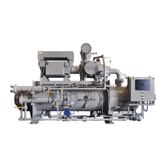
- Page 1 VSG/VSSG compressor unit Installation, operation & maintenance manual FOR UNITS BUILT AFTER JULY 1, 2013...
-
Page 3: Vsg/Vssg Standard Vilter Warranty Statement
Any suggestions by Seller or Seller’s agents regarding use, application or suitability of the products shall not be construed as an express warranty unless confi rmed to be such in writing by Seller. VSG/VSSG • Installation, Operation and Maintenance Manual •Vilter/Emerson • 35391STG... -
Page 4: Important Message
Equipment Identification Numbers: Vilter Order Number: _______________________Compressor Serial Number: _________________ Vilter Order Number: _______________________Compressor Serial Number: _________________ Vilter Order Number: _______________________Compressor Serial Number: _________________ Vilter Order Number: _______________________Compressor Serial Number: _________________ VSG/VSSG • Installation, Operation and Maintenance Manual •Vilter/Emerson • 35391STG... -
Page 5: Table Of Contents
Using Non-Vilter Oils ........................3-16 Unit Oil Charging and Priming ....................3-16 Priming Oil Cooler (Shell and Tube)and Piping................3-16 Priming Compressor and Oil Filters .................... 3-18 TOC - 1 VSG/VSSG • Installation, Operation and Maintenance Manual •Vilter/Emerson • 35391STG... - Page 6 Gate Rotor Thrust Bearing Removal/Installation ................. 5-31 Gate Rotor Roller Bearing Removal/Installation ................5-31 Slide Valve Actuator Assembly Replacement ..................5-32 Command Shaft Assembly Replacement ....................5-33 Command Shaft Seal Replacement ......................5-33 TOC - 2 VSG/VSSG • Installation, Operation and Maintenance Manual •Vilter/Emerson • 35391STG...
- Page 7 Torque Specifications ...................... A Appendix B Oil Analysis Report ......................B Appendix C Recommended Header Piping ..................C Appendix D Recommended Remote Air Cooled Oil Cooler Piping ............D TOC - 3 VSG/VSSG • Installation, Operation and Maintenance Manual •Vilter/Emerson • 35391STG...
- Page 8 Figure 4-1. Oil Operating Levels ......................4-1 Figure 4-2. Actuator Assembly ....................... 4-3 Figure 4-3. Overview, Main Menu and Instrument Calibration Screens (Compact Logix PLC) ....4-4 TOC - 4 VSG/VSSG • Installation, Operation and Maintenance Manual •Vilter/Emerson • 35391STG...
- Page 9 Figure 5-32. Thrust Bearing Installation ....................5-31 Figure 5-33. Roller Bearing Assembly ..................... 5-32 Figure 5-34. Command Shaft Seal ......................5-33 Figure 5-35. Command Shaft Seal Installation ..................5-34 TOC - 5 VSG/VSSG • Installation, Operation and Maintenance Manual •Vilter/Emerson • 35391STG...
-
Page 10: Vsg/Vssg • Installation, Operation And Maintenance Manual •Vilter/Emerson • 35391Stg
Blank / TOC VSG/VSSG • Installation, Operation and Maintenance Manual •Vilter/Emerson • 35391STG... -
Page 11: Section 1 • General Information
NOTE - Notes are shown when there are additional infor- mation pertaining to the instructions explained. 1 – 1 VSG/VSSG • Installation, Operation and Maintenance Manual •Vilter/Emerson • 35391STG... -
Page 12: Gas Compressor Unit Model Designations
GL = Glycol HN = High Stage no Oil Pump AIR = Air 6. Driver VFD = Variable Frequency Drive EMD = Electric Motor Drive ENG = Engine Drive 1 – 2 VSG/VSSG • Installation, Operation and Maintenance Manual •Vilter/Emerson • 35391STG... -
Page 13: System Unit Identification
A compressor unit typically a single screw compressor unit, is not mounted on a structural steel base. Package Unit A package unit is a complete system mounted on a structural steel base with interconnecting piping. 1 – 3 VSG/VSSG • Installation, Operation and Maintenance Manual •Vilter/Emerson • 35391STG... -
Page 14: Compressor Unit Component Identification
17 - Discharge Connection 8 - PLC Panel 18 - Oil Separator Inspection Port 10 - Oil Pump Figure 1-2. Gas Compressor Unit Components (1 of 3) 1 – 4 VSG/VSSG • Installation, Operation and Maintenance Manual •Vilter/Emerson • 35391STG... - Page 15 Section 1 • General Information Section 1 • General Information Figure 1-2. Gas Compressor Unit Components (2 of 3) 1 – 5 VSG/VSSG • Installation, Operation and Maintenance Manual •Vilter/Emerson • 35391STG...
- Page 16 2) 27 - RTD (Suction) 35 - RTD (Oil Separator) 28 - Volume Slide Valve Actuator OUTLET INLET Figure 1-2. Gas Compressor Unit Components (3 of 3) 1 – 6 VSG/VSSG • Installation, Operation and Maintenance Manual •Vilter/Emerson • 35391STG...
-
Page 17: Instrument Identification Letters
Flow Control Valve Control LALL Liquid Level Low Low Differential Pressure Flow/Relay/Convertor (Shutdown) Indication Level Controller PDIC Pressure Differential Gas Detecting Indicating Indicating Controller Level Probe (Element) Transmitter 1 – 7 VSG/VSSG • Installation, Operation and Maintenance Manual •Vilter/Emerson • 35391STG... - Page 18 Variable Frequency Drive Heater Element, Immersion, Tracing Block/Bleed, Gauge Valve Vibration Switch High Radiation VSHH Vibration Switch High Speed, Frequency High (Shutdown) Speed Control Vibration Transmitter Shutdown (Blind) 1 – 8 VSG/VSSG • Installation, Operation and Maintenance Manual •Vilter/Emerson • 35391STG...
-
Page 19: Symbol Identification
Use this list to identify major components shown in the Piping & Identifi cation Diagram. Shell and Tube Air Drive Filter Heat Exchanger Finned Tube Compressor Heat Exchanger Tank/Drum Vessel Damper or Heat Exchanger Louver Motor Engine Drive Positive Displacement Pump 1 – 9 VSG/VSSG • Installation, Operation and Maintenance Manual •Vilter/Emerson • 35391STG... -
Page 20: Control And Instrument Identification
X X X X X Electrical Signal Internal System Link (Software or Data Link) Mechanical Link Hydraulic Signal L L L L L Customer Field Piping Insulation 1 – 10 VSG/VSSG • Installation, Operation and Maintenance Manual •Vilter/Emerson • 35391STG... -
Page 21: Valve And Instrument Tagging
P - Pumps B - Blowers R - Reactors C - Compressors U - Filters, Strainers D - Drivers V - Vessels, Tanks, Separators, Scrubbers E - Heat Exchangers 1 – 11 VSG/VSSG • Installation, Operation and Maintenance Manual •Vilter/Emerson • 35391STG... -
Page 22: Pipe Line Data Identification
HR - Hydrocarbon Refrigerant D - Numerical Sequence Number E - Size #” - Nominal Pipe Size (Inches) F - Standard/Other Standard STD -Vilter 0 - Other Standard (Not Vilter) 1 – 12 VSG/VSSG • Installation, Operation and Maintenance Manual •Vilter/Emerson • 35391STG... -
Page 23: Section 2 • Theory Of Operation
The high pressure gas fl ows out to The life of the oil is directly affected by the quality of the 2 – 1 VSG/VSSG • Installation, Operation and Maintenance Manual •Vilter/Emerson • 35391SSG... -
Page 24: Control System
(8 or 9) is piped in parallel to the oil tem- perature control valve (oil mixing vlave) (10), which acts as a by-pass valve. This is a continuous cycle. 2 – 2 VSG/VSSG • Installation, Operation and Maintenance Manual •Vilter/Emerson • 35391SSG... -
Page 25: Section 3 • Installation
Use lifting chains/straps and spreader bar. Evenly distribute weight. Keep lifting chains and spreader bar clear of components to prevent damage. Figure 3-1. Rigging and Lifting Points 3 – 1 VSG/VSSG • Installation, Operation and Maintenance Manual •Vilter/Emerson • 35391STG... -
Page 26: Long Term Storage Recommendations
(approximately 6) every 3 months to prevent fl at spots on the bearing surfaces. If the compressor unit is installed, wired and charged with oil, open all oil 3 – 2 VSG/VSSG • Installation, Operation and Maintenance Manual •Vilter/Emerson • 35391STG... -
Page 27: Air Cooled Oil Coolers
Division 1 or Division 2 and with ability to overcome suction pressure) • Sockets and wrenches up to 2-1/2” (63.5 mm) • Torque Wrenches (with ranges from 0 to 600 ft-lbs) • Voltmeter 3 – 3 VSG/VSSG • Installation, Operation and Maintenance Manual •Vilter/Emerson • 35391STG... -
Page 28: Long Term Storage Log
Long Term Storage Log Company: Sales Order Number: Serial Number: Name (Please Print): Initial: Date (M/D/Y): PSI Nitrogen Pressure - Current PSI Nitrogen Pressure - Recharged (If pressure is low, identify and fi x leak prior to recharging, see Compressor Unit Leak Check procedure in Section 5) Nitrogen Leak Location (Briefl... -
Page 29: Foundation
• Lightening protection for outdoor installations • Ensure the foundation rests entirely on natural rock • Relief valve venting or entirely on solid earth, but never on a combination 3 – 5 VSG/VSSG • Installation, Operation and Maintenance Manual •Vilter/Emerson • 35391STG... -
Page 30: Figure 3-2. Concrete Pad With Compressor Unit Dimensions - Side View
Figure 3-4. Next, place your rebar in the forms as per the and prepare to grout. Vilter foundation drawing. When all rebars are in place the concrete can be poured. The concrete must then be 3 – 6 VSG/VSSG • Installation, Operation and Maintenance Manual •Vilter/Emerson • 35391STG... -
Page 31: Figure 3-3. Concrete Pad With Compressor Unit Dimensions - Front View
Figure 3-3. Concrete Pad with Compressor Unit Dimensions - Front View ISOLATION JOINT, 1" MINIMUM THICKNESS COMPRESSOR UNIT CHAMFER EDGE FOUNDATION CONCRETE SLAB IN BUILDING 6” Figure 3-4. Interior Foundation Isolation 3 – 7 VSG/VSSG • Installation, Operation and Maintenance Manual •Vilter/Emerson • 35391STG... -
Page 32: Figure 3-5. Foundation With Housekeeping Pads Dimensions - Top View
• Concrete poured on and permanently cast against the earth OVER ALL G.A. LENGTH + 4'-0" CENTER LINE GAS COMPRESSION SYSTEM Figure 3-5. Foundation with Housekeeping Pads Dimensions - Top View 3 – 8 VSG/VSSG • Installation, Operation and Maintenance Manual •Vilter/Emerson • 35391STG... -
Page 33: Figure 3-6. Housekeeping Pad Dimension Detail - Top View
Figure 3-6. Housekeeping Pad Dimension Detail - Top View COMPRESSOR UNIT LEVEL HOUSEKEEPING PADS SPHERICAL WASHERS Figure 3-7. Level Compressor Unit Using Top Surface of Spherical Washers 3 – 9 VSG/VSSG • Installation, Operation and Maintenance Manual •Vilter/Emerson • 35391STG... -
Page 34: Piping
IMPORTANT – piping elements shall be supported per the requirements of ASME B31.5 / B31.3 as applicable. See guidelines below, particularly with concern to mini- mizing loads on check valves. 3 – 10 VSG/VSSG • Installation, Operation and Maintenance Manual •Vilter/Emerson • 35391STG... -
Page 35: Table 3-2. Maximum Allowable Flange Loads
LINE IS MOUNTED HERE 5 PIPE DIAMETERS 3-4 PIPE 5 PIPE DIAMETERS DIAMETERS CHECK VALVE SUCTION LINE CUSTOMER SUPPORT CUSTOMER SUPPORT Figure 3-9. Maximum Allowable Flange Loads 3 – 11 VSG/VSSG • Installation, Operation and Maintenance Manual •Vilter/Emerson • 35391STG... -
Page 36: General Installation Guideline For Multiple Air Coolers Installed In A Common Area
We will look at each rule and provide pictorials and PREFERRED TOTAL INTAKE PERIMETER = 82 FEET Figure 3-10. Installation of Coolers - One Fan Diameter Next to Building 3 – 12 VSG/VSSG • Installation, Operation and Maintenance Manual •Vilter/Emerson • 35391STG... -
Page 37: Figure 3-11. Leg Height
500FPM. We know the following: NOT PREFERRED TOTAL INTAKE PERIMETER = 57 FEET Figure 3-12. Installation of Coolers - Next to Buildling 3 – 13 VSG/VSSG • Installation, Operation and Maintenance Manual •Vilter/Emerson • 35391STG... -
Page 38: Hot Air Recirculation
The best way to address this is to increase the leg heights on coolers 1 and 2 as shown in the preferred confi guration. 3 – 14 VSG/VSSG • Installation, Operation and Maintenance Manual •Vilter/Emerson • 35391STG... -
Page 39: Figure 3-13. Discharge Elevation Of Coolers
Section 3 • Installation NOT PREFERRED PREFERRED Figure 3-13. Discharge Elevation of Coolers NOT PREFERRED PREFERRED Figure 3-14. Cooler Placement and Spacing 3 – 15 VSG/VSSG • Installation, Operation and Maintenance Manual •Vilter/Emerson • 35391STG... -
Page 40: Pressure Testing
(9) is constant. Avoid skin contact with oil. Wear rubber gloves and a face shield when working with oil. Failure to comply may result in serious injury or death. 3 – 16 VSG/VSSG • Installation, Operation and Maintenance Manual •Vilter/Emerson • 35391STG... -
Page 41: Figure 3-15. Oil Operating Levels
View Rotate 180° View From Back - View Rotate 180° Oil Filter Shut-Off Valves Figure 3-16. Suction Oil Charging Valve, Oil Cooler Drain Valve and Oil Filter Shut-Off Valves 3 – 17 VSG/VSSG • Installation, Operation and Maintenance Manual •Vilter/Emerson • 35391STG... -
Page 42: Priming Compressor And Oil Filters
DRAIN OPEN CLOSE OIL FILTER CLOSE MOTOR OIL MIXING VALVE OIL PUMP OIL FILTER CLOSE DRAIN BLEED Figure 3-17. Priming Oil Cooler (Shell & Tube) and Piping 3 – 18 VSG/VSSG • Installation, Operation and Maintenance Manual •Vilter/Emerson • 35391STG... -
Page 43: Figure 3-18. Priming Compressor (With Shell & Tube Oil Cooler) And Piping
OPEN OIL FILTER OPEN MOTOR OIL MIXING VALVE OIL PUMP OIL FILTER OPEN DRAIN BLEED Figure 3-18. Priming Compressor (with Shell & Tube Oil Cooler) and Piping 3 – 19 VSG/VSSG • Installation, Operation and Maintenance Manual •Vilter/Emerson • 35391STG... -
Page 44: Priming Remote Oil Cooler And Piping (Initial Oil Charging)
1000W 1000W DRAIN OPEN CLOSE OIL FILTER CLOSE MOTOR OIL MIXING VALVE OIL PUMP OIL FILTER CLOSE DRAIN BLEED Figure 3-19. Priming Remote Oil Cooler and Piping 3 – 20 VSG/VSSG • Installation, Operation and Maintenance Manual •Vilter/Emerson • 35391STG... -
Page 45: Priming Compressor And Oil Filters
1000W 1000W 1000W DRAIN CLOSE OPEN OIL FILTER OPEN MOTOR OIL MIXING VALVE OIL PUMP OIL FILTER OPEN DRAIN BLEED Figure 3-20. Priming Compressor and Oil Filters 3 – 21 VSG/VSSG • Installation, Operation and Maintenance Manual •Vilter/Emerson • 35391STG... -
Page 46: Pre Start-Up
Refer to supplied GA drawing for connection points and piping sizes. (Continued on next page) 3 – 22 VSG/VSSG • Installation, Operation and Maintenance Manual •Vilter/Emerson • 35391STG... - Page 47 20. Keep a hard copy of the fi nal set points in case the micro-controller gets corrupted or if they are required by Vilter technicians for troubleshooting. 3 – 23 VSG/VSSG • Installation, Operation and Maintenance Manual •Vilter/Emerson • 35391STG...
-
Page 48: Start-Up
13. Verify operation of all safeties. 14. Set scaling for main motor amps in PLC. 15. Record running data and fi nal set points on data sheets. 16. Instruct Operators. 3 – 24 VSG/VSSG • Installation, Operation and Maintenance Manual •Vilter/Emerson • 35391STG... -
Page 49: Section 4 • Operation
Inspect oil level through sight glasses on the oil Normal Operating Level Maximum NON-Operating Level Minimum Operating Level Figure 4-1. Oil Operating Levels 4 – 1 VSG/VSSG • Installation, Operation and Maintenance Manual •Vilter/Emerson • 35391STG... -
Page 50: Control System Calibration
• Compressor unit starting up for the fi rst time. load and unload and vary the volume ratio in response • A new actuator motor has been installed. to the system demands. 4 – 2 VSG/VSSG • Installation, Operation and Maintenance Manual •Vilter/Emerson • 35391STG... -
Page 51: Figure 4-2. Actuator Assembly
If the compressor unit is starting for the fi rst time or a new actuator was installed, connect connec- tors of power cable and position transmitter cable to new actuator. 4 – 3 VSG/VSSG • Installation, Operation and Maintenance Manual •Vilter/Emerson • 35391STG... -
Page 52: Figure 4-3. Overview, Main Menu And Instrument Calibration Screens (Compact Logix Plc)
Section 4 • Operation Figure 4-3. Overview, Main Menu and Instrument Calibration Screens (Compact Logix PLC) 4 – 4 VSG/VSSG • Installation, Operation and Maintenance Manual •Vilter/Emerson • 35391STG... -
Page 53: Figure 4-4. Slide Calibration Screen (Compact Logix Plc)
This places the actuator in Press down on Photo-chopper to release tension from mo- calibration mode. The red LED will begin fl ashing tor shaft. rapidly. 4 – 5 VSG/VSSG • Installation, Operation and Maintenance Manual •Vilter/Emerson • 35391STG... -
Page 54: Table 4-1. Command Shaft Rotation Specifications
The brake can be disengaged by pushing on the motor shaft on the cone end. The shaft should be centered in its travel. Do not use excessive force manually operating the motor or damage may result. 4 – 6 VSG/VSSG • Installation, Operation and Maintenance Manual •Vilter/Emerson • 35391STG... - Page 55 16. Use the DOWN button to move the actuator to- wards its minimum position while watching the mV readout on the Control Panel screen. Discontinue pressing the DOWN button when the mV reading 4 – 7 VSG/VSSG • Installation, Operation and Maintenance Manual •Vilter/Emerson • 35391STG...
-
Page 56: Oil Temperature Control Valve (Oil Mixing Valve) Operation
If value is 0%, return actuator to CLOSE position as shown on the visual indicator. Actuator Visual Indicator Figure 4-6. Oil Temperature Control Valve (Oil Mixing Valve) 4 – 8 VSG/VSSG • Installation, Operation and Maintenance Manual •Vilter/Emerson • 35391STG... -
Page 57: Purging With Dry Nitrogen
Lockout/tagout valves. Close any other valves that may feed gas or oil to Discharge Status Stop Button Figure 4-7. PLC Main Screen 4 – 9 VSG/VSSG • Installation, Operation and Maintenance Manual •Vilter/Emerson • 35391STG... -
Page 58: Figure 4-8. Equalizing Solenoid
Figure 4-8. Equalizing Solenoid View Rotate 90° Discharge Bleed Valves Suction Oil Charging Valve View Rotate 90° Figure 4-9. Suction Oil Charging Valve and Discharge Bleed Valve 4 – 10 VSG/VSSG • Installation, Operation and Maintenance Manual •Vilter/Emerson • 35391STG... -
Page 59: Purging With Dry Gas
DISCHARGE OUTLET DRAIN SUCTION INLET OIL CHARGE REMOTE OIL COOLER BLEED MOTOR COMPRESSOR VENT BLEED OIL SEPARATOR DRAIN 1000W 1000W 1000W DRAIN Figure 4-10. Customer Purge Line 4 – 11 VSG/VSSG • Installation, Operation and Maintenance Manual •Vilter/Emerson • 35391STG... -
Page 60: Figure 4-11. Plc Main Screen
Failure to comply may result in damage to equipment. Discharge Status Stop Button Figure 4-11. PLC Main Screen 4 – 12 VSG/VSSG • Installation, Operation and Maintenance Manual •Vilter/Emerson • 35391STG... -
Page 61: Figure 4-12. Equalizing Solenoid
Section 4 • Operation Equalizing Solenoid for Suction Bypass Figure 4-12. Equalizing Solenoid Suction Oil Charging Valve View Rotate 90° Figure 4-13. Suction Oil Charging Valve 4 – 13 VSG/VSSG • Installation, Operation and Maintenance Manual •Vilter/Emerson • 35391STG... -
Page 62: Coalescing Oil Return Line Setup
While the unit is in operation, crack open needle valve and observe oil fl ow through sight-glass. Needle Valve Check Valve Coalescing Oil Return Line Sight-Glass Shut-Off Valve Figure 4-14. Coalescing Oil Return Line 4 – 14 VSG/VSSG • Installation, Operation and Maintenance Manual •Vilter/Emerson • 35391STG... -
Page 63: Section 5 • Maintenance/Service
Section 5 • Maintenance/Service Maintenance and Service Schedule Follow this table for maintaining and servicing the compressor unit at hourly intervals. 5 – 1 VSG/VSSG • Installation, Operation and Maintenance Manual •Vilter/Emerson • 35391STG... -
Page 64: Maintaining Proper Operation
Shut down the compressor unit, refer to Stopping/ Restarting procedure in Section 4. View Rotate 180° Suction Bypass Valve (Manual) Figure 5-1. Suction By-Pass Valve Location (Manual) (1 of 2) 5 – 2 VSG/VSSG • Installation, Operation and Maintenance Manual •Vilter/Emerson • 35391STG... -
Page 65: Compressor Unit Leak Check
Line from Oil Separator Separator Needle Shut-off to Shut-off Valve Line from Needle Valve Valve Valve to Suction Figure 5-1. Suction By-Pass Valve Location (Equalizing Solenoid) (2 of 2) 5 – 3 VSG/VSSG • Installation, Operation and Maintenance Manual •Vilter/Emerson • 35391STG... -
Page 66: Oil System Components
• Ensure samples are taken as scheduled in the Maintenance and Service Schedule. • Send samples immediately to the oil analysis lab after sampling, do not wait 24 hours. Figure 5-2. Oil Analysis Kit 5 – 4 VSG/VSSG • Installation, Operation and Maintenance Manual •Vilter/Emerson • 35391STG... -
Page 67: Oil Charging
View From Back - View Rotate 180° Oil Drain Valve (Oil Separator) Figure 5-3. Suction Oil Charging Valve, Oil Cooler Drain Valve and Oil Filter Shut-Off Valves 5 – 5 VSG/VSSG • Installation, Operation and Maintenance Manual •Vilter/Emerson • 35391STG... -
Page 68: Oil Draining
Cover Flange Element Cover Flange Elements Spring Plate Spring Plate Canister Canister Outlet Element Outlet Inlet Inlet Centering Piece Figure 5-4. Oil Filter Assemblies (Single and Dual) 5 – 6 VSG/VSSG • Installation, Operation and Maintenance Manual •Vilter/Emerson • 35391STG... -
Page 69: Figure 5-5. Oil Filter Drain, Vent And Shut-Off Valves
fi lter canister. Retain fi lter element centering piece. Thoroughly clean the oil fi lter canister, spring plate and centering piece. Inspect spring plate and 5 – 7 VSG/VSSG • Installation, Operation and Maintenance Manual •Vilter/Emerson • 35391STG... -
Page 70: Coalescing Oil Filter Replacement
Service Interval, see Table 5-1. Maintenance & Service 10. Install tubing over hold-down rod. Position tubing Interval. as far back as possible. 11. With assistance of second person, position 5 – 8 VSG/VSSG • Installation, Operation and Maintenance Manual •Vilter/Emerson • 35391STG... -
Page 71: Oil Pump Strainer
Nuts Strainer Cover View from back of oil pump strainer View rotated 180° Strainer Oil Pump Drain Valve Strainer Figure 5-7. Oil Pump Strainer and Drain Valve 5 – 9 VSG/VSSG • Installation, Operation and Maintenance Manual •Vilter/Emerson • 35391STG... -
Page 72: Table 5-3. Shaft And Hub Distances
Between Hub Size Straight Motor Shaft Straight Motor Shaft Faces Combination Combination BP38U BP41U BP47U 6.25” 5.125” 5.00” (158.75 mm) (130.18 mm) (127 mm) BP54U BP54U BP56U 5 – 10 VSG/VSSG • Installation, Operation and Maintenance Manual •Vilter/Emerson • 35391STG... -
Page 73: Drive Center Member (Form-Flex Bpu) Installation And Alignment
23. Install bolts and locking nuts to secure both disc packs to center member. Hub Distance Figure 5-8. Hub Distance (Axial Spacing) 5 – 11 VSG/VSSG • Installation, Operation and Maintenance Manual •Vilter/Emerson • 35391STG... -
Page 74: Figure 5-9. Angular Alignment And Parallel Offset
23 (31) 10 (13) BH47U 3/8-24 49 (66) 20 (27) BH54U 7/16-20 78 (106) 20 (27) BH56U 1/2-20 120 (163) 40 (54) DP42 1/2-20 120 (163) 20 (27) 5 – 12 VSG/VSSG • Installation, Operation and Maintenance Manual •Vilter/Emerson • 35391STG... -
Page 75: Drive Coupling (Type C Sure-Flex) Replacement
Remove hub and key from motor shaft. large washer and hub from shaft. 10. Loosen set screw in compressor hub securing key in keyway. 11. Loosen clamping bolts securing hub from 5 – 13 VSG/VSSG • Installation, Operation and Maintenance Manual •Vilter/Emerson • 35391STG... - Page 76 Screw Torque Specifi cations Type C ft-lbs (Nm) Coupling Size Clamping Key Set Bolts Screw 13 (18) 13 (18) 23 (31) 13 (18) 23 (31) 50 (68) 50 (68) 5 – 14 VSG/VSSG • Installation, Operation and Maintenance Manual •Vilter/Emerson • 35391STG...
-
Page 77: Compressor Replacement
30. Tighten nuts on ‘discharge pipe-to-compressor fl ange’ fi rst, then tighten nuts on ‘discharge pipe- to-oil separator fl ange’, see Appendix A. 5 – 15 VSG/VSSG • Installation, Operation and Maintenance Manual •Vilter/Emerson • 35391STG... -
Page 78: Figure 5-10. Compressor Replacement And Hardware Assembly (Models 2401-3001 Shown)
Check procedure. Compressor Lock Washer Flat Washer Spherical Frame Shim Washer Assembly Stud Flat Washer Lock Washer Figure 5-10. Compressor Replacement and Hardware Assembly (Models 2401-3001 Shown) 5 – 16 VSG/VSSG • Installation, Operation and Maintenance Manual •Vilter/Emerson • 35391STG... -
Page 79: Bare Shaft Compressor Lifting Points And Weights
Gate Rotor Cover Gate Rotor Bearing Housing Discharge Manifold Gate Rotor Bearing Housing Cover Model 1551-2101 Shown Figure 5-11. Bare Shaft Compressor Lifting Points and Component Weights 5 – 17 VSG/VSSG • Installation, Operation and Maintenance Manual •Vilter/Emerson • 35391STG... -
Page 80: Bare Shaft Compressor Center Of Gravity (Models 291-2101)
Lifting Eyes Main Compressor Discharge Assembly Manifold Center of Gravity Range Figure 5-13. Bare Shaft Compressor Center of Gravity - Discharge Manifold and Main Compressor Assembly (Models 291-2101) 5 – 18 VSG/VSSG • Installation, Operation and Maintenance Manual •Vilter/Emerson • 35391STG... -
Page 81: Bare Shaft Compressor Center Of Gravity (Models 2401-3001)
Lifting Eyes Center of Gravity Discharge Main Compressor Manifold Assembly Figure 5-15. Bare Shaft Compressor Center of Gravity - Discharge Manifold and Main Compressor Assembly (Models 2401-3001) 5 – 19 VSG/VSSG • Installation, Operation and Maintenance Manual •Vilter/Emerson • 35391STG... -
Page 82: Figure 5-16. Bearing Axial Float Inspection (Compressor)
Place lever arm and fulcrum behind compressor coupling half and push the coupling towards the motor. Record measurement. Figure 5-16. Bearing Axial Float Inspection Re-zero indicator, now position the fulcrum on the 5 – 20 VSG/VSSG • Installation, Operation and Maintenance Manual •Vilter/Emerson • 35391STG... -
Page 83: Gate Rotor Float And Gate Rotor Bearing Float Inspection
Rigidly attach dial indicator. Direction of shaft movement. Main Rotor Damper Pin Applied Force Bushing Figure 5-17. Bearing Radial Float Inspection Float Figure 5-18. Gate Rotor Float 5 – 21 VSG/VSSG • Installation, Operation and Maintenance Manual •Vilter/Emerson • 35391STG... -
Page 84: Table 5-10. Gate Rotor Float
Compressor Unit Leak Check procedure. Inspect main rotor and gate rotor for abnormal wear due to dirt or other contaminants. If dam- aged, replace gate rotor and/or main rotor. 5 – 22 VSG/VSSG • Installation, Operation and Maintenance Manual •Vilter/Emerson • 35391STG... -
Page 85: Gate Rotor And Support Clearance
Figure 5-20. Repeat steps 1 to 2 to check gap along entire gate rotor edge on both sides. Figure 5-20. Gate Rotor and Support Clearance - Minimum Clearances 5 – 23 VSG/VSSG • Installation, Operation and Maintenance Manual •Vilter/Emerson • 35391STG... -
Page 86: Figure 5-21. Gate Rotor And Support Clearance - Measuring
Straight Edge Gate Rotor Gate Rotor Support Straight Edge Gate Rotor Gate Rotor Support Straight Edge Gate Rotor Figure 5-21. Gate Rotor and Support Clearance - Measuring 5 – 24 VSG/VSSG • Installation, Operation and Maintenance Manual •Vilter/Emerson • 35391STG... -
Page 87: Gate Rotor Assembly Replacement (All Vsg & Vssg Compressors Except Vsg 301-701 Compressors)
Re-install two bolts into the threaded jacking holes 20. Place a piece of 0.003”-0.004” shim stock between to assist in removing thrust bearing cover. Retain gate rotor blade and shelf. 5 – 25 VSG/VSSG • Installation, Operation and Maintenance Manual •Vilter/Emerson • 35391STG... -
Page 88: Figure 5-22. Gate Rotor Assembly Removal And Tools
Position leading edge of main rotor groove fl ush with or slightly below back of gate rotor support. Figure 5-22. Gate Rotor Assembly Removal and Tools Figure 5-23. Gate Rotor Assembly Removal 5 – 26 VSG/VSSG • Installation, Operation and Maintenance Manual •Vilter/Emerson • 35391STG... -
Page 89: Figure 5-24. Gate Rotor Assembly And Tools
Check for 0.003-0.004” (0.076- 0.102 mm) clearance between gate rotor blade and partition. Figure 5-25. Gate Rotor and Shelf Clearance Figure 5-24. Gate Rotor Assembly and Tools 5 – 27 VSG/VSSG • Installation, Operation and Maintenance Manual •Vilter/Emerson • 35391STG... -
Page 90: Gate Rotor Assembly Replacement (Vsg 301-701 Compressors Only)
On dual gate versions, repeat the procedure for the remaining gate rotor support assembly. INSTALLATION Figure 5-26. Gate Rotor Assembly Breakdown 10. Install the gate rotor support. Carefully tilt the roller 5 – 28 VSG/VSSG • Installation, Operation and Maintenance Manual •Vilter/Emerson • 35391STG... -
Page 91: Figure 5-27. Gate Rotor Thrust Bearing
Check for 0.003-0.004” (0.076- 0.102 mm) clearance between gate rotor blade and partition. Figure 5-28. Gate Rotor and Shelf Clearance Figure 5-27. Gate Rotor Thrust Bearing 5 – 29 VSG/VSSG • Installation, Operation and Maintenance Manual •Vilter/Emerson • 35391STG... -
Page 92: Gate Rotor Disassembly
Figure 5-30. Gate Rotor Blade Installation Figure 5-29. Gate Rotor Blade Assembly 5 – 30 VSG/VSSG • Installation, Operation and Maintenance Manual •Vilter/Emerson • 35391STG... -
Page 93: Gate Rotor Thrust Bearing Removal/Installation
This means that the larger race. Install the snap ring retainer in the housing. 5 – 31 VSG/VSSG • Installation, Operation and Maintenance Manual •Vilter/Emerson • 35391STG... -
Page 94: Slide Valve Actuator Assembly Replacement
NOTE This procedure is applicable to both capacity and volume slide valve actuator assemblies. Shut down the compressor unit, refer to Stopping/ 5 – 32 VSG/VSSG • Installation, Operation and Maintenance Manual •Vilter/Emerson • 35391STG... -
Page 95: Command Shaft Assembly Replacement
(see tool (219B) from the seal cover using a brass drift and lists). hammer to tap it out from the back side of the seal 5 – 33 VSG/VSSG • Installation, Operation and Maintenance Manual •Vilter/Emerson • 35391STG... -
Page 96: Figure 5-35. Command Shaft Seal Installation
If the seal is not fully seated against the shoulder, the shaft seal carbon will be damaged when the seal cover is installed. Figure 5-35. Command Shaft Seal Installation 5 – 34 VSG/VSSG • Installation, Operation and Maintenance Manual •Vilter/Emerson • 35391STG... -
Page 97: Table 6-1. Slide Valve Actuator Troubleshooting Guide (1 Of 2)
Get the motor brake to where it op- correct position after a power loss properly erates freely and then recalibrate. The position sensor’s EEPROM Replace the actuator. memory has failed 6 – 1 VSG/VSSG • Installation, Operation and Maintenance Manual •Vilter/Emerson • 35391STG... - Page 98 Stripped gears inside the gear The motor runs but output shaft will motor or the armature has come un- Replace the actuator. not turn pressed from the armature shaft 6 – 2 VSG/VSSG • Installation, Operation and Maintenance Manual •Vilter/Emerson • 35391STG...
-
Page 99: Table 6-2. Slide Valve Actuator Led Blink Codes* (1 Of 2)
Shade the actuator when the cover is off for service and calibration. Do not operate the actuator with the cover off. 6 – 3 VSG/VSSG • Installation, Operation and Maintenance Manual •Vilter/Emerson • 35391STG... - Page 100 Note 2: The TS1 wire pads are where the motor thermal switch leads solder into the circuit board. They are clearly marked on the board silkscreen legend and are oriented at a 45 degree angle. 6 – 4 VSG/VSSG • Installation, Operation and Maintenance Manual •Vilter/Emerson • 35391STG...
-
Page 101: Table 6-3. Troubleshooting Guide - General Problems & Solutions (1 Of 3)
• Check cable connections at device, terminal strips, and PLC input card for readings correct wiring and shielding (RF noise). • Check calibration of RTDs and transducers. 6 – 5 VSG/VSSG • Installation, Operation and Maintenance Manual •Vilter/Emerson • 35391STG... - Page 102 • Command shaft broken Symptoms: • Slide valve rack or rack shaft damaged • Check balance piston movement • Reference Slide Valve Actuator Troubleshooting Guide • Check I/O fusing 6 – 6 VSG/VSSG • Installation, Operation and Maintenance Manual •Vilter/Emerson • 35391STG...
- Page 103 • Check condition of compressor and motor (i.e. alignments) • If there is more than normal motor backspin at shutdown, check suction Excessive Motor Backspin check valve for proper operation. 6 – 7 VSG/VSSG • Installation, Operation and Maintenance Manual •Vilter/Emerson • 35391STG...
- Page 104 6 – 8 / Blank VSG/VSSG • Installation, Operation and Maintenance Manual •Vilter/Emerson • 35391STG...
-
Page 105: Section 7 • Warranty And Parts
• Please include a copy of the RMA document in the box for identifi cation purposes when the part is received. Part to be evaluated. 7 – 1 VSG/VSSG • Installation, Operation and Maintenance Manual •Vilter/Emerson • 35391STG... -
Page 106: Explanation Of Rebuild Levels
Level 2 Compressor is in good condition, but requires new gate rotor blades. Replace all items in Level 1 plus new gate rotor blades and bushings. 7 – 2 VSG/VSSG • Installation, Operation and Maintenance Manual •Vilter/Emerson • 35391STG... -
Page 107: Appendix A Torque Specifications
Hex & Socket Head Cap Screws NOTE: Continue use of red loctite #271 (VPN 2205E) on currently applied locations. Use blue loctite #243 (VPN 2205F or 2205G) on all remaining locations. VSG/VSSG • Installation, Operation and Maintenance Manual •Vilter/Emerson • 35391STG... -
Page 108: Appendix B Oil Analysis Report
1-800-637-8628, or fax 1-989-496-2313 or email us at [email protected] CC List Accuracy of recommendations is dependent on representative oil samples and complete correct data on both unit and oil * Property values should not be construed as specifications VSG/VSSG • Installation, Operation and Maintenance Manual •Vilter/Emerson • 35391STG... -
Page 109: Appendix C Recommended Header Piping
Appendix C • Recommended Header Piping VSG/VSSG • Installation, Operation and Maintenance Manual •Vilter/Emerson • 35391STG... - Page 110 OUTLET ON TOP INLET ON BOTTOM Recommended location of drain connections as required. • Vertical drops should be no higher than 8 to 10 feet. • If there is no choice and the vertical drops need to be higher, then an electronic service valve needs to be installed in the return line at the compressor.
- Page 112 35391STG Rev. 0 (8/13) Emerson and Vilter are trademarks of Emerson Electric Co. or one of its affi liated companies. © 2013 Emerson Climate Technologies, Inc. All rights reserved. Printed in the USA.