
Related Manuals for Emerson Copeland Scroll YBVH021 1U-3E9


Summary of Contents for Emerson Copeland Scroll YBVH021 1U-3E9
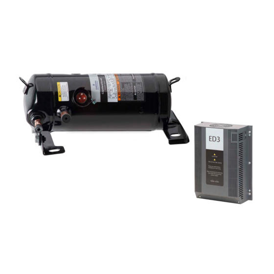
- Page 1 Application Guidelines Copeland Scroll Variable Speed ™ Horizontal Refrigeration Compressors for R290 Applications...
-
Page 2: Table Of Contents
About these guidelines ....................1 Safety instructions ................... 1 1.1 Icon explanation ....................... 1 1.2 Safety statements ......................2 1.3 General instructions ......................2 Product description ..................3 2.1 General information about Copeland Scroll™ compressors ........... 3 2.2 Matched-pairs of compressor and drive ................3 2.3 Variable speed advantages ..................... - Page 3 4.2.4 Removing the molded plug power cable ............18 4.3 Wiring diagrams ......................19 4.3.1 Motor windings ....................20 4.4 Protection devices ......................20 4.5 Crankcase heating function ................... 20 4.6 Pressure safety controls ....................20 4.6.1 High-pressure protection ..................20 4.6.2 Low pressure protection ..................
- Page 4 6.8 Oil additives ........................31 Troubleshooting ..................... 32 Dismantling & disposal .................. 35 DISCLAIMER ......................35 C6.2.38/0719/E...
-
Page 6: About These Guidelines
The purpose of these guidelines is to provide guidance in the application of Copeland Scroll™ compressors and Emerson control drives in users’ systems working with propane. They are intended to answer the questions raised while designing, assembling and operating a system with these products. -
Page 7: Safety Statements
Safety statements ▪ Refrigerant compressors must be employed only for their intended use. The system has to be labelled according to the applicable standards and legislation. ▪ Only qualified and authorized HVAC or refrigeration personnel are permitted to install commission and maintain this equipment. Only competent personnel (as specified in EN 13313) qualified for flammable refrigerant handling is permitted to commission, initiate and maintain the compressor/refrigeration systems;... -
Page 8: Product Description
(for example Emerson drive ED3), either single-phase or three-phase, referred to as the "ED3 drive" throughout these guidelines. NOTE: For more information on the motor control drive refer to the Emerson User Manual for ED3. Matched-pairs of compressor and drive... -
Page 9: Variable Speed Advantages
IP65, no mounting parts Application considerations 2.6.1 Qualified refrigerant and oil Oil recharge values can be taken from Copeland Scroll compressors brochures or Copeland™ brand products Select software available at www.climate.emerson.com/en-gb. Compressors YBVH021, YBVH029, YBVH046 Qualified refrigerant R290... -
Page 10: Oil Filling And Oil Level
A sample compressor equipped with an external oil sight tube can be ordered from Emerson for lab testing – see Figure 3. For all new systems with YBVH* compressors, it is mandatory to check and test the oil distribution and compressor oil filling using a dedicated sample compressor equipped with an external oil sight tube. -
Page 11: Test Procedure
The oil tests on sample compressors with an external oil sight tube must be carried out by the system designer in the lab. This will allow to investigate the oil return behaviour to the compressor. In case some oil remains in the system, eg, in the tubes, heat exchangers or other components, oil top-up is required. -
Page 12: Admissible Pressure, Temperature And Relative Humidity Ranges
10K is required. In the same way, the superheat at the compressor suction must always stay below a maximum limit specified by Emerson, depending on the model and for which the operating envelope is defined. - Page 13 Running outside the envelope is not allowed. Emerson’s recommendation is to start with a speed of 3000 rpm and to freeze the speed for minimum 30 seconds or longer until the system is in stable operation – see Figure 7 "Ramp up".
-
Page 14: Design Features
30 minutes but users must be aware that unloading noise from the compressor can occur. ▪ Fast speed changes can cause instable control, eg, on the superheat control. Per Emerson experience speed changes should be in the range of 10 to 60 rpm/s depending on the system reaction. -
Page 15: Dimensions
Dimensions The external dimensions of YBVH* compressors are shown in Figures 8 & 9 below. Figure 8: YBVH* compressors external dimensions – top view Figure 9: YBVH* compressors external dimensions – side view C6.2.38/0719/E... -
Page 16: Installation
Installation WARNING High pressure! Injury to skin and eyes possible! Be careful when opening connections on a pressurized item. Compressor and drive handling WARNING Static electricity! Personal injuries! Personnel handling the drives in a manufacturing plant environment should guard against static electricity by using the appropriate equipment - antistatic wrist straps and mats. -
Page 17: Compressor Brazing Procedure
Mounting parts YBVH021, YBVH029, YBVH046 – Soft mountings Figure 11: Rubber mounting part with sleeve Compressor brazing procedure WARNING Air/flammable refrigerant mixture! Creation of a potentially flammable atmosphere! Fire hazard! Remove all refrigerant before opening the system. When working on a refrigerant-filled system, make sure to follow the safety and working instructions given in Chapter 6 "Maintenance &... -
Page 18: Suction Accumulators
Such blockage can result in compressor failure. Sound shell No sound shell attenuation for YBVH* compressors is available from Emerson at this time. If a sound shell is still needed, particular attention shall be paid to the electrostatic charge of the insulation material, which could be a potential ignition source –... -
Page 19: Insulation Material
Since Copeland scroll compressors have a very high volumetric efficiency their displacements are lower than those of equivalent capacity reciprocating compressors. As a result, Emerson recommends that the capacity rating on reversing valves be no more than 1.5 to 2 times the nominal capacity of the compressor in order to ensure proper operation of the reversing valve under all operating conditions. -
Page 20: Sound And Vibrations
3.10 Sound and vibrations WARNING Vibration! Creation of flammable atmosphere! Carefully check the system for vibrations. It is necessary to ensure that the piping design is adequate when connecting a scroll compressor to a system. A scroll compressor makes both a rocking and twisting motion and enough flexibility must be provided in the pipe-lines to allow starting, stopping and steady state running of the compressor without transmitting excessive stress into any line attached to the unit. -
Page 21: Electrical Connection
Before connecting the compressor, ensure the supply voltage, the phases and the frequency match the nameplate data. For safety reasons, Emerson recommends that the electrical installation be executed in compliance with standard EN 60204-1 and/or other standards and regulations of application when dealing with A3 flammable refrigerants. -
Page 22: Terminal Connections
4.2.1 Terminal connections WARNING Ignition source in a potentially flammable atmosphere! Fire hazard! Any work on the energized terminals in the compressor terminals could create an ignition. Do not touch the energized terminals with a tool or cable when the compressor is energized. -
Page 23: Assembly Of The Molded Plug Cable
▪ Remove the molded plug connector from the connection pins. ▪ Disconnect the grounding from the compressor circle fence. NOTE: To select the appropriate molded plug power cables, please refer to the Emerson spare parts software available at www.climate.emerson.com/en-gb. C6.2.38/0719/E... -
Page 24: Wiring Diagrams
Wiring diagrams For the single-phase and three-phase matched pairs of YBVH* compressor and ED3 drive, the following circuit diagrams can be used: Power circuit Control circuit Legend B1 ..System controller K2 ..Contactor (optional) Q1 ..Main switch RCD ..Residual current device D .. -
Page 25: Motor Windings
5VDC signal. Normally the high-pressure cut-out limiter must be closed. If the limiter is open, the drive will not operate. NOTE: For the connection of the high-pressure limiter to the drive, please refer to the Emerson User Manual for ED3. 4.6.2 Low pressure protection WARNING Operation under ambient pressure! Fire hazard! During operation under ambient pressure, a flammable mixture can form inside the system. -
Page 26: Discharge Gas Temperature Protection
These conditions may result in compressor failure. Therefore, Emerson requires that all YBVH compressors without exception be fitted with a low- pressure protection in the suction line, meaning that no service valve between compressor and pressure limiter is allowed. -
Page 27: Compressor Discharge Gas Temperature Protection
ED3 inverter – see the Emerson User Manual for ED3 for correct connection and further details. The NTC-sensor must be attached to the compressor discharge line less than 12 cm from the compressor discharge fitting. -
Page 28: Start-Up & Operation
System contamination! Bearing malfunction! Use only dry nitrogen) for pressure testing. DO NOT USE other industrial gases. The compressor has been strength-tested in the Emerson factory. As the compressor complies with EN 60335-2-34, it is not necessary for the manufacturer/installer to strength-test the compressor. -
Page 29: Preliminary Checks - Pre-Starting
axially seal with the scroll set, with the higher pressure on the floating seal. Consequently, until the pressures equalise, the floating seal and scroll set can be held tightly together. The highest demands are placed on the leak-proof design of the installation and on the leak testing methods (please refer to EN 378). -
Page 30: Run-In Time
The drive controls the start and stop routine of the variable speed scroll. This routine allows for soft starting and controlled stopping, an advantage over traditional on/off control of fixed capacity units. For more information about this topic please refer to the Emerson User Manual for ED3. Starting sound During the very brief start-up, a clicking sound is audible, resulting from initial contacting of the spirals;... -
Page 31: Minimum Run Time
Emerson for oil return qualification and minimum oil level – see Chapter 2.6.3 "Oil filling and oil level". Install it in a system with the longest connecting lines that are approved for the system. -
Page 32: Maintenance & Repair
Maintenance & repair WARNING Conductor cables! Electrical shock! Follow the lockout/tag out procedure and the national regulations before carrying out any maintenance or service work on the system. Use compressor with grounded system only. Screwed electrical connections must be used in all applications. Refer to original equipment wiring diagrams. Electrical connections must be made by qualified electrical personnel. -
Page 33: Preparation And Work Procedure
Preparation and work procedure A work procedure shall be provided in the preparation stage. All maintenance staff and others working at the site shall be instructed on the nature of the work being carried out. If any work is to be conducted on the refrigeration systems or any associated parts, appropriate fire extinguishing equipment shall be provided. -
Page 34: Replacing A Compressor
CAUTION Low suction pressure operation! Compressor damage! Do not operate with a restricted suction. Do not operate with the low-pressure limiter bridged. Do not operate compressor at pressures that are not allowed by the operating envelope. Allowing the suction pressure to drop below the envelope limit for more than a few seconds may overheat scrolls and cause early drive bearing and moving parts damage. -
Page 35: Lubrication And Oil Removal
Since POE holds moisture more readily than mineral oil it is more difficult to remove it through the use of vacuum. Compressors supplied by Emerson contain oil with low moisture content, and it may rise during the system assembling process. Therefore, it is recommended that a properly sized filter-drier is installed in all POE systems. -
Page 36: Oil Additives
Oil additives Although Emerson cannot comment on any specific product, from our own testing and past experience, we do not recommend the use of any additives to reduce compressor bearing losses or for any other purpose. -
Page 37: Troubleshooting
Troubleshooting Most in-warranty electrical failures are the result of mechanical problems (particles in the oil, liquid refrigerant in the oil, etc.) and most mechanical problems are the result of system problems. Unless the reason for the failure is found, replacing the compressor will probably lead to another compressor failure. - Page 38 Condition Cause Corrective action Defective Check if the pressure control or thermostat works system control properly or if the controls are open. components Power circuit Check the fuse for a tripped circuit breaker or for an open open disconnected switch. ▪...
- Page 39 Too high Make sure the compressor operates within the compressor acceptable superheat range published by Emerson. superheat Excessive cooling/heating Check the load design; make sure that proper load or insulation is applied.
-
Page 40: Dismantling & Disposal
3. Emerson does not assume responsibility for the selection, use or maintenance of any product. Responsibility for proper selection, use and maintenance of any Emerson product remains solely with the purchaser or end user. - Page 41 The Emerson logo is a trademark and service mark of Emerson Electric Co. Emerson Climate Technologies Inc. is a subsidiary of Emerson Electric Co. Copeland is a registered trademark and Copeland Scroll is a trademark of Emerson Climate Technologies Inc.. All other trademarks are property of their respective owners.