
Related Manuals for Emerson Copeland Scroll ZB50KCE


Summary of Contents for Emerson Copeland Scroll ZB50KCE
- Page 1 Application Guidelines Copeland Scroll Compressors ™ for Refrigeration ZB50KCE to ZB114KCE, ZB66K5E to ZB114K5E ZF25K5E to ZF54K5E...
-
Page 2: Table Of Contents
About these guidelines ....................1 Safety instructions ................... 1 1.1 Icon explanation ....................... 1 1.2 Safety statements ......................1 1.3 General instructions ......................2 Product description ..................3 2.1 Common information about Copeland Scroll compressors ..........3 2.2 Nomenclature ........................3 2.3 BOM Variation ........................ - Page 3 5.3.3 Crankcase heaters ..................... 14 5.4 Pressure safety controls ....................14 5.4.1 High pressure control ..................14 5.4.2 Low pressure control ..................14 5.5 Discharge temperature protection ................. 15 5.5.1 ASTP Advanced Scroll Temperature Protection ..........15 5.5.2 Discharge line thermostat................... 15 5.6 Motor protection ......................
-
Page 4: About These Guidelines
Besides the support they provide, the instructions listed herein are also critical for the proper and safe functioning of the compressors. Emerson will not guarantee the performance and reliability of the product if it is misused in regard of these guidelines. -
Page 5: General Instructions
General instructions WARNING System breakdown! Personal injuries! Never install a system in the field and leave it unattended when it has no charge, a holding charge, or with the service valves closed without electrically locking out the system. System breakdown! Personal injuries! Only approved refrigerants and refrigeration oils must be used. -
Page 6: Product Description
Product description Common information about Copeland Scroll compressors The Scroll compressor has been under development at Emerson since 1979. It is the most efficient and durable compressor Emerson has ever developed for air conditioning, refrigeration and heating applications. These application guidelines deal with vertical single Copeland Scroll compressors ZB50KCE to ZB114KCE &... -
Page 7: Application Range
It is essential that the glide of refrigerant blends (primarily R407A and R407F) be carefully considered when adjusting pressure and superheat controls. Oil recharge values can be taken from Copeland Scroll compressors brochures or Copeland™ brand products Select software available at www.climate.emerson.com/en-gb. ZB*KCE ZB*K5E... -
Page 8: Installation
If the compressors are mounted in tandem or used in parallel, then the hard mountings (bolt M9 5/16") are recommended. The mounting torque should be 27 ± 1 Nm. It is possible to deliver these hard-mounting parts as a kit. See Emerson spare parts software for reference. C6.2.27/0716-0219/E... -
Page 9: Brazing Procedure
Mounting parts ZB50K* to ZB114K* and ZF25K* to ZF54K* - Soft mountings Figure 2: Mounting parts Brazing procedure IMPORTANT Blockage! Compressor breakdown! Maintain a flow of oxygen-free nitrogen through the system at very low pressure during brazing. Nitrogen displaces the air and prevents the formation of copper oxides in the system. -
Page 10: Shut-Off Valves And Adaptors
Rotalock 1 ¾" – 12 UNF 170 - 180 Table 3 NOTE: More information about adaptors and shut-off valves can be found in the "Spare parts list" available at www.climate.emerson.com/en-gb. Suction accumulators CAUTION Inadequate lubrication! Bearing destruction! Minimise liquid refrigerant returning to the compressor. -
Page 11: Screens
Screens CAUTION Screen blocking! Compressor breakdown! Use screens with at least 0.6 mm openings. The use of screens finer than 30 x 30 mesh (0.6 mm openings) anywhere in the system should be avoided with these compressors. Field experience has shown that finer mesh screens used to protect thermal expansion valves, capillary tubes or accumulators can become temporarily or permanently plugged with normal system debris and block the flow of either oil or refrigerant to the compressor. -
Page 12: Zf*K5E Compressors For Low Temperature Applications
ZF*K5E compressors for low temperature applications ZF*K5E compressors are designed and applicable for both liquid injection and vapour injection (EVI). For low temperature applications of ZF*K5E models, liquid or vapour injection is required to keep discharge gas temperatures within safe limits. The documented application limits (see Chapter 2.4.3 "Application limits"... -
Page 13: Compressor Or Valve Service
4.1.3 Compressor or valve service When replacing a ZF compressor using the DTC valve it is recommended to replace both the DTC valve and the compressor at the same time. The filter in the liquid line should also be replaced. ZF*K5E compressors with vapour injection 4.2.1 Economized Vapour Injection technology (EVI) The Economized Vapour Injection (EVI) technology has been developed to provide improved... -
Page 14: Zf*K5E Compressors With Wet Vapour Injection
Special care has to be given to the design of the heat exchanger and of the thermostatic expansion valve (TXV) to allow for part-load operation. Good refrigerant distribution is required in the common heat exchanger as well as sufficient velocities for oil return, even at part load. In the case of a large range of capacity modulation (more than 2 compressors in parallel), the use of an electronic expansion valve (EXV) or two different TXV’s controlled by individual solenoid valves, may be necessary. -
Page 15: Electrical Connection
Electrical connection General recommendations The compressor terminal box has a wiring diagram on the inside of its cover. Before connecting the compressor, ensure the supply voltage, the phases and the frequency match the nameplate data. Electrical installation Three-phase compressors (TF*) with internal motor protection: Power circuit Control circuit Motor terminal connections... -
Page 16: Terminal Box
Terminal box The protection class for the terminal box is IP21 for compressors ZB50KCE to ZB114KCE BOM 551 version, and IP54 for all ZB*K5E and ZF*K5E models, according to IEC 60034-5. Cable glands have an influence on the protection class of the terminal box. It is strongly recommended to use appropriate cable glands in order to reach the rated protection class. -
Page 17: Motor Windings
A molded plug version is available as an option for compressor models ZB50KCE to ZB114KCE BOM 651 version. The molded plug version is compliant with all CE and safety regulations and its protection class is IP66. The benefits of the molded plug version include ease of installation, reduced assembly time and consequent reduced customer’s applied costs. -
Page 18: Discharge Temperature Protection
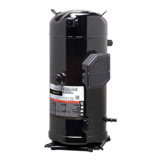
Discharge temperature protection 5.5.1 ASTP Advanced Scroll Temperature Protection Scroll compressor models ZB50KCE to ZB114KCE have the addition of the Advanced Scroll Temperature Protection (ASTP). The Advanced Scroll Temperature Protection is also a temperature sensitive thermo-disc that acts to protect the compressor from discharge gas overheating. - Page 19 Discharge thermostat DTC valve cap DTC valve Figure 15: Example of ZF*K5E-TFD installation, liquid injection with DTC valve and discharge thermostat on the discharge line Assembly of the discharge line thermostat For installation, please follow the recommendations below. ▪ Install the discharge line thermostat on the discharge tube 120 mm from top cap.
-
Page 20: Motor Protection
Emerson subjects all Scroll compressors to a high-voltage test after final assembly. Each motor phase winding is tested, according to EN 0530 or VDE 0530 part 1, at a differential voltage of 1000V plus twice the nominal voltage. -
Page 21: Starting Up & Operation
Starting up & operation WARNING Diesel effect! System explosion! The mixture of air and oil at high temperature can lead to an explosion. Avoid operating with air. IMPORTANT Oil dilution! Bearing malfunction! Turn the crankcase heater on 12 hours before starting the compressor. Strength pressure test The compressor has been strength-tested in the factory. -
Page 22: Charging Procedure
▪ Pressure and compound gauges fitted ▪ Correctly charged with refrigerant ▪ Compressor electrical isolator location & position Charging procedure CAUTION Low suction pressure operation! Compressor Damage! Do not operate with a restricted suction. Do not operate with the low-pressure cut-out bridged. Do not operate compressor without enough system charge to maintain at least 0.3 bar suction pressure. -
Page 23: Starting Sound
(available from Emerson) and install it in a system with the longest connecting lines that are approved for the system. The minimum on time becomes the time required for oil lost during compressor start- up to return to the compressor sump and restore a minimal oil level that will ensure oil pick-up through the crankshaft. -
Page 24: Shut-Off Sound
6.13 Shut-off sound Scroll compressors incorporate a device that minimizes reverse rotation. The residual momentary reversal of the scrolls at shut-off will cause a clicking sound, but it is entirely normal and has no effect on compressor durability. 6.14 Frequency There is no general release of standard Copeland Scroll compressors for use with variable speed AC drives. -
Page 25: Maintenance & Repair
Maintenance & repair Exchanging the refrigerant Qualified refrigerants and oils are shown in section 2.4.1. It is not necessary to replace the refrigerant with new unless contamination due to an error such as topping up the system with an incorrect refrigerant is suspected. To verify correct refrigerant composition, a sample can be taken for chemical analysis. -
Page 26: Oil Additives
Compressors supplied by Emerson contain oil with low moisture content, and it may rise during the system assembling process. Therefore it is recommended that a properly sized filter-drier is installed in all POE systems. -
Page 27: Dismantling & Disposal
3. Emerson does not assume responsibility for the selection, use or maintenance of any product. Responsibility for proper selection, use and maintenance of any Emerson product remains solely with the purchaser or end user. - Page 28 The Emerson logo is a trademark and service mark of Emerson Electric Co. Emerson Climate Technologies Inc. is a subsidiary of Emerson Electric Co. Copeland is a registered trademark and Copeland Scroll is a trademark of Emerson Climate Technologies Inc.. All other trademarks are property of their respective owners.