beautypg.com
Manuals
Brands
Emerson Manuals
Air Compressor
Vilter VSSG
Emerson Vilter VSSG Manuals
Manuals and User Guides for Emerson Vilter VSSG. We have
1
Emerson Vilter VSSG manual available for free PDF download: Installation, Operation & Maintenance Manual
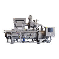
Emerson Vilter VSSG Installation, Operation & Maintenance Manual (112 pages)
Compressor unit
Brand:
Emerson
| Category:
Air Compressor
| Size: 6.01 MB
Table of Contents
VSG/VSSG Standard Vilter Warranty Statement
3
Important Message
4
Table of Contents
5
Section 1 • General Information
11
How to Use this Manual
11
Gas Compressor Unit Model Designations
12
Figure 1-1. Gas Compressor Unit Model Designation
12
System Unit Identification
13
Compressor Unit Component Identification
14
Figure 1-2. Gas Compressor Unit Components
14
Instrument Identification Letters
17
Symbol Identification
19
Major Component Identification
19
Control and Instrument Identification
20
Line Type Designations
20
Valve and Instrument Tagging
21
Equipment Number Identification
21
Pipe Line Data Identification
22
Section 2 • Theory of Operation
23
Gas Flow
23
Oil Life and Oil Flow
23
Figure 2-1. Gas Compressor Unit P&ID
23
Control System
24
Rtds and Pressure Transducers
24
Section 3 • Installation
25
Delivery Inspection
25
Rigging and Lifting
25
Figure 3-1. Rigging and Lifting Points
25
Long Term Storage Recommendations
26
Compressor Motor
26
Air Cooled Oil Coolers
27
Compressor Unit Inspections Prior to Storage or Installation
27
Recommended Onsite Tools
27
Long Term Storage Log
28
Foundation
29
Figure 3-2. Concrete Pad with Compressor Unit Dimensions - Side View
30
Figure 3-3. Concrete Pad with Compressor Unit Dimensions - Front View
31
Figure 3-4. Interior Foundation Isolation
31
Figure 3-5. Foundation with Housekeeping Pads Dimensions - Top View
32
Figure 3-6. Housekeeping Pad Dimension Detail - Top View
33
Figure 3-7. Level Compressor Unit Using Top Surface of Spherical Washers
33
Piping
34
Header Piping and Drains
34
Remote Air Cooled Oil Cooler Piping
34
Figure 3-8. Concrete Pad Housekeeping Detail
34
Table 3-2. Maximum Allowable Flange Loads
35
Figure 3-9. Maximum Allowable Flange Loads
35
General Installation Guideline for Multiple Air Coolers Installed in a Common Area
36
Free Flow
36
One Fan Diameter
36
Intake Velocity
36
Figure 3-10. Installation of Coolers - One Fan Diameter Next to Building
36
Figure 3-11. Leg Height
37
Hot Air Recirculation
38
Figure 3-13. Discharge Elevation of Coolers
39
Figure 3-14. Cooler Placement and Spacing
39
Pressure Testing
40
Initial Oil Charging
40
Using Non-Vilter Oils
40
Unit Oil Charging and Priming
40
Priming Oil Cooler (Shell and Tube)And Piping
40
Figure 3-15. Oil Operating Levels
41
Priming Compressor and Oil Filters
42
Section 3 • Installation (Continued)
42
Figure 3-17. Priming Oil Cooler (Shell & Tube) and Piping
42
Figure 3-18. Priming Compressor (with Shell & Tube Oil Cooler) and Piping
43
Figure 3-19. Priming Remote Oil Cooler and Piping
44
Priming Remote Oil Cooler and Piping (Initial Oil Charging)
44
Figure 3-20. Priming Compressor and Oil Filters
45
Priming Compressor and Oil Filters
45
Pre Start-Up
46
Start-Up
48
Section 4 • Operation
49
Oil Inspection
49
Dual Oil Filters
49
Figure 4-1. Oil Operating Levels
49
Control System Calibration
50
Starting, Stopping and Restarting the Compressor
50
Calibrate Slide Valve Actuators
50
Figure 4-2. Actuator Assembly
51
Figure 4-3. Overview, Main Menu and Instrument Calibration Screens (Compact Logix PLC)
52
Figure 4-4. Slide Calibration Screen (Compact Logix PLC)
53
Figure 4-5. Photo-Chopper
53
Table 4-1. Command Shaft Rotation Specifications
54
Oil Temperature Control Valve (Oil Mixing Valve) Operation
56
Manual Override
56
Figure 4-6. Oil Temperature Control Valve (Oil Mixing Valve)
56
Purging with Dry Nitrogen
57
Figure 4-7. PLC Main Screen
57
Figure 4-8. Equalizing Solenoid
58
Figure 4-9. Suction Oil Charging Valve and Discharge Bleed Valve
58
Purging with Dry Gas
59
Figure 4-10. Customer Purge Line
59
Figure 4-11. PLC Main Screen
60
Figure 4-12. Equalizing Solenoid
61
Figure 4-13. Suction Oil Charging Valve
61
Coalescing Oil Return Line Setup
62
Figure 4-14. Coalescing Oil Return Line
62
Section 5 • Maintenance/Service
63
Maintenance and Service Schedule
63
Maintaining Proper Operation
64
Compressor Unit Isolation for Maintenance/Service
64
Compressor Unit Leak Check
65
Oil System Components
66
Oil Sampling
66
Figure 5-2. Oil Analysis Kit
66
Oil Charging
67
Oil Draining
68
Oil Filter Replacement
68
Table 5-2. Oil Filter Elements and Compressor Models
68
Figure 5-4. Oil Filter Assemblies (Single and Dual)
68
Figure 5-5. Oil Filter Drain, Vent and Shut-Off Valves
69
Coalescing Oil Filter Replacement
70
Figure 5-6. Oil Separator Manhole Cover and Coalescing Filter Assembly
70
Oil Pump Strainer
71
Figure 5-7. Oil Pump Strainer and Drain Valve
71
Table 5-3. Shaft and Hub Distances
72
Drive Center Member (Form-Flex BPU) Installation and Alignment
73
Figure 5-8. Hub Distance (Axial Spacing)
73
Figure 5-9. Angular Alignment and Parallel Offset
74
Drive Coupling (Type C Sure-Flex) Replacement
75
Compressor Replacement
77
Figure 5-10. Compressor Replacement and Hardware Assembly (Models 2401-3001 Shown)
78
Bare Shaft Compressor Lifting Points and Weights
79
Figure 5-11. Bare Shaft Compressor Lifting Points and Component Weights
79
Table 5-7. Bare Shaft Compressor Component Weights
79
Table 5-8. Bare Shaft Compressor Component Lifting Hole Sizes
79
Bare Shaft Compressor Center of Gravity (Models 291-2101)
80
Figure 5-12. Bare Shaft Compressor Assembly Center of Gravity (Models 291-2101)
80
Figure 5-13. Bare Shaft Compressor Center of Gravity - Discharge Manifold and Main Compressor Assembly (Models 291-2101)
80
Bare Shaft Compressor Center of Gravity (Models 2401-3001)
81
Figure 5-14. Bare Shaft Compressor Assembly Center of Gravity (Models 2401-3001)
81
Figure 5-15. Bare Shaft Compressor Center of Gravity - Discharge Manifold and Main Compressor Assembly (Models 2401-3001)
81
Figure 5-16. Bearing Axial Float Inspection (Compressor)
82
Gate Rotor Float and Gate Rotor Bearing Float Inspection
83
Table 5-9. Maximum Bearing Float (Compressor Shaft)
83
Figure 5-17. Bearing Radial Float Inspection (Compressor)
83
Figure 5-18. Gate Rotor Float
83
Table 5-10. Gate Rotor Float
84
Figure 5-19. Gate Rotor Bearing Float
84
Gate Rotor and Support Clearance
85
Figure 5-20. Gate Rotor and Support Clearance - Minimum Clearances
85
Figure 5-21. Gate Rotor and Support Clearance - Measuring
86
Gate Rotor Assembly Replacement (All VSG & VSSG Compressors Except VSG 301-701 Compressors)
87
Table 5-11. Gate Rotor Tool Sets
87
Figure 5-22. Gate Rotor Assembly Removal and Tools
88
Figure 5-24. Gate Rotor Assembly and Tools
89
Figure 5-25. Gate Rotor and Shelf Clearance
89
Gate Rotor Assembly Replacement (VSG 301-701 Compressors ONLY)
90
Figure 5-26. Gate Rotor Assembly Breakdown
90
Figure 5-27. Gate Rotor Thrust Bearing
91
Figure 5-28. Gate Rotor and Shelf Clearance
91
Gate Rotor Disassembly
92
Gate Rotor Blade Removal/Installation
92
Figure 5-29. Gate Rotor Blade Assembly
92
Figure 5-30. Gate Rotor Blade Installation
92
Gate Rotor Thrust Bearing Removal/Installation
93
Gate Rotor Roller Bearing Removal/Installation
93
Figure 5-31. Gate Rotor Thrust Bearing
93
Figure 5-32. Thrust Bearing Installation
93
Slide Valve Actuator Assembly Replacement
94
Figure 5-33. Roller Bearing Assembly
94
Command Shaft Assembly Replacement
95
Command Shaft Seal Replacement
95
Figure 5-34. Command Shaft Seal
95
Figure 5-35. Command Shaft Seal Installation
96
Table 6-1. Slide Valve Actuator Troubleshooting Guide (1 of 2)
97
Table 6-2. Slide Valve Actuator LED Blink Codes* (1 of 2)
99
Table 6-3. Troubleshooting Guide - General Problems & Solutions (1 of 3)
101
Section 7 • Warranty and Parts
105
On Site Service Support
105
Explanation of Rebuild Levels
106
Bare Shaft Compressor Description
106
Warranty Claim Processing
105
Appendix A Torque Specifications
107
Appendix B Oil Analysis Report
108
Appendix C Recommended Header Piping
109
Related Products
Emerson Vilter VSG
Emerson VILTER VSR
Emerson Vilter VSS
Emerson Vilter VSM
Emerson Vilter VSH
Emerson Vilter VSSH
Emerson VILTER VSG
Emerson VILTER VSSG
Emerson VSG & VSSG
Emerson Vilter VSG145
Emerson Categories
Controller
Control Unit
Transmitter
Measuring Instruments
Fan
More Emerson Manuals