beautypg.com
Manuals
Brands
Emerson Manuals
Air Compressor
Vilter VSH
Emerson Vilter VSH Manuals
Manuals and User Guides for Emerson Vilter VSH. We have
2
Emerson Vilter VSH manuals available for free PDF download: Installation, Operation & Maintenance Manual, Installation, Operation And Service Manual
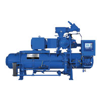
Emerson Vilter VSH Installation, Operation & Maintenance Manual (250 pages)
Compressor Unit
Brand:
Emerson
| Category:
Air Compressor
| Size: 14.94 MB
Table of Contents
Standard Vilter™ Warranty Statement
3
Important Message
5
EC Declaration of Incorporation
6
Table of Contents
7
Section 1 • General Information
15
How to Use this Manual
15
Additional Important Notes
15
Refrigeration Compressor Unit Model Designations
16
System Unit Identification
17
Compressor Unit Component Identification
18
Figure 1-1. Refrigeration Compressor Unit Components
18
Instrument Identification Letters
21
Symbols Identification
23
Major Component Identification
23
Control and Instrument Identification
24
Line Type Designations
24
Valve and Instrument Tagging
25
Equipment Number Identification
25
Pipe Line Data Identification
26
Section 2 • Theory of Operation
27
Refrigerant Flow
27
Oil Life and Oil Flow
27
Oil Cooling
28
Water Cooled Oil Cooling
28
Liquid Injection Oil Cooling
28
V-Plus Oil Cooling
28
Thermosyphon Oil Cooling
28
Control System
29
Temperature Elements, Pressure Transmitters and Indicators
29
Section 3 • Installation
31
Figure 3-1. Rigging and Lifting Points (VSS-2101 Compressor Unit Shown)
31
Delivery Inspection
31
Rigging and Lifting of Compressor Unit
31
Compressor Unit Inspections Prior to Installation
32
Recommended On-Site Tools
32
Long Term Storage Recommendations
33
Compressor Motor
33
Long Term Storage Log
34
Foundation
35
Considerations Prior to Starting
35
Foundation Materials
35
Building the Foundation
35
Compressor Unit Installation
36
Figure 3-2. Concrete Pad with Compressor Unit Dimensions - Side View
36
Leveling and Grouting
37
Figure 3-3. Concrete Pad with Compressor Unit Dimensions - Front View
37
Figure 3-4. Interior Foundation Isolation
37
Additional Information
38
Operation and Performance
38
General Design Requirements
38
Figure 3-5. Foundation with Housekeeping Pads Dimensions - Top View
38
Figure 3-6. Housekeeping Pad Dimension Detail - Top View
39
Figure 3-7. Level Compressor Unit Using Top Surface of Spherical Washers
39
Figure 3-8. Concrete Pad Housekeeping Detail
40
Figure 3-9. Stop/Check Valve Orientation
41
Stop/Check Valve Installation
41
Piping
42
Table 3-1. Maximum Allowable Flange Loads
43
Figure 3-10. Maximum Allowable Flange Loads
43
Flange Loads
43
Figure 3-11. Recommended Remote Air Cooled Oil Cooler Piping
44
Remote Air-Cooled Oil Cooler Piping
44
Electrical Connections
45
Field Wiring Instructions
45
Testing Refrigeration System for Leaks
48
Ammonia Systems
48
Halocarbon Refrigerant Systems
48
CO2 Systems
49
Evacuating the System
49
Notice on Using Non-Vilter Oils
50
Unit Oil Charging and Priming
50
Unit Initial Oil Charging
51
Priming Oil Lines and Compressor
51
System Refrigerant Charging
52
Low Side Equipment
52
Compressors
52
Condensers
52
Controls
52
Initial High Side Charging
52
Notice on Using Non-Vilter Oils
55
Operation
55
Oil Inspection
55
Section 4 • Operation
55
Dual Oil Filters
56
Control System
56
Calibration
56
Starting, Stopping and Restarting the Compressor
56
Emergency Shutdown
57
Slide Valve Actuator Operation
57
Calibrate Slide Valve Actuators (for Units Using Vission20/20™)
58
Table 4-1. Command Shaft Rotation Specifications
62
Calibrate Slide Valve Actuators (for Units Using Compact Logix PLC)
64
Compressor Control with Vission20/20™ Micro-Controller (no Slide Operation)
69
Coalescing Oil Return Line Setup
70
Suction Equalizing Line Setup - for VSS/VSM Compressors
71
Dual Oil Filter Setup for Oil Filters with Filter Head Assemblies
72
Table 4-2. Stop/Check Valve Open Positions
73
Stop/Check Valve Operation
73
Maintenance and Service Schedule - for VSS/VSM Unit Only
75
Section 5 • Maintenance/Service
75
Maintenance and Service Schedule - for VSH/VSSH Unit Only
76
Preventive Maintenance, Checks and Services
78
Daily
78
Weekly
78
Monthly
78
Trimonthly
78
Annually
78
Compressor Unit Isolation for Maintenance/Service (Compressors with Slide Valves)
79
Recommendations When Servicing (Compressors Without Slide Valves)
80
Preparation of Unit for Servicing
80
Compressor Unit Leak Check after Servicing
81
Oil System Components
81
Oil Sampling
81
Recommendations
81
Installation of the Oil Sampler Valve
82
Pre-Sampling
82
Sampling Procedure
82
Oil Sample Analysis Report
84
Oil Draining
85
Oil Charging
86
Tool Required
86
Charging During Operation
86
Charging During Shutdown
86
Filter Element Replacement (Single Oil Filter Assembly) and Oil Pump Strainer Servicing
87
Drain Oil from Isolated Oil Line
87
Table 5-3. Oil Filter Replacement Parts Required
87
Oil Filter Element Removal (for 3111A Oil Filter Housing)
88
Oil Filter Element Removal (for 3110A or 3112A Oil Filter Housing)
88
Oil Pump Strainer Screen Removal and Service
88
Oil Pump Strainer Screen Installation
89
Oil Filter Element Installation (for 3111A Oil Filter Housing)
89
Oil Filter Element Installation (for 3110A or 3112A Oil Filter Housing)
89
Filter Element Replacement (Duplex Oil Filter Assembly)
90
Removal
90
Filter Element Replacement (Dual Oil Filter Assembly)
90
Switching Oil Filters for Maintenance
92
Drain Oil from Isolated Oil Filter
93
Oil Filter Element Removal (for 3111A Oil Filter Housing)
93
Oil Filter Element Removal (for 3110A or 3112A Oil Filter Housing)
94
Oil Filter Element Installation (for 3111A Oil Filter Housing)
94
Oil Filter Element Installation (for 3110A or 3112A Oil Filter Housing)
94
Oil Separator Coalescing Filter Replacement
95
Removal
95
Installation
95
Oil Separator Heater Cartridge Replacement
97
Parts Required
97
Removal
97
Installation
98
Drive Coupling Hub (Form-Flex BPU) Installation
98
Straight Bore Hubs
98
Tapered Bore Hubs
98
Table 5-4. Shaft and Hub Distances
98
Table 5-5. Hub Clamp Bolt and Set Screw Torque Specifications
99
Table 5-6. Disc Pack Installation Torque Specifications
99
Drive Center Member Installation and Alignment
99
Drive Coupling Hub (Form-Flex BPU) and Center Member Removal
101
Drive Coupling (Type C Sure-Flex) Replacement
101
Removal
101
Installation
102
Coupling Guard Replacement
103
Removal
103
Installation
103
Compressor Replacement
104
Removal
104
Installation
105
Table 5-8. Bareshaft Compressor Component Weights
105
Table 5-9. Bareshaft Compressor Component Lifting Hole Sizes
105
Bareshaft Compressor Lifting Points and Weights
105
Bareshaft Compressor Center of Gravity (Models 291-2101)
107
Bareshaft Compressor Center of Gravity (Models 2401-3001)
108
Compressor Inspection
109
Compressor Shaft Bearing Clearance Inspections
109
Determine Maximum Applied Force
109
Main Rotor Bearing Axial Clearance Inspection
109
Main Rotor Bearing Radial Clearance Inspection
110
Table 5-10. Maximum Main Rotor Bearing Clearance
110
Gaterotor Bearing Inspection
111
Table 5-11. Maximum Gaterotor Bearing Clearance
111
Gaterotor Inspection
112
A) Gaterotor - Main Housing Shelf Clearance
112
B) Gaterotor Float Measurement
113
Table 5-12. Gaterotor Float
113
C) Gaterotor Backlash Inspection
114
Table 5-13. Backlash Range
115
Important Notes
116
Additional Inspections
116
Post Inspection
116
Gaterotor Assembly Replacement (All Compressors Except VSM 301-701 & VSM 97-127 Compressors)
116
Removal
116
Table 5-14. Gaterotor Tool Kits
116
Installation
117
Gaterotor Assembly Replacement (VSM 301-701 Compressors Only)
120
Removal
120
Installation
120
Gaterotor Assembly Replacement (VSM 97-127 Compressors Only)
122
Removal
122
Installation
122
Gaterotor Disassembly (All Compressors Except VSM 97-127 Compressors)
124
Gaterotor Blade Removal
124
Gaterotor Blade Installation
125
Gaterotor Thrust Bearing Removal
125
Gaterotor Thrust Bearing Installation
125
Gaterotor Roller Bearing Removal
126
Gaterotor Roller Bearing Installation
126
Gaterotor Disassembly (VSM 97-127 Compressors Only)
127
Gaterotor Blade Removal
127
Gaterotor Blade Installation
127
Gaterotor Thrust Bearing Removal
128
Gaterotor Thrust Bearing Installation
128
Gaterotor Roller Bearing Removal
128
Gaterotor Roller Bearing Installation
128
Compressor Shaft Seal Replacement
129
Shaft Seal Assembly
129
Handling Seal Face with Care
129
Compressor Shaft Seal Replacement - for VSS/VSM Units
130
Tools
130
Removal
130
Installation
130
Table 5-15. Shaft Seal Tool Kits
130
Compressor Shaft Seal Replacement - for VSH/VSSH Units
132
Shaft Seal Removal -For Part# 25985Y and 25985YA
132
Table 5-16. VSH/VSSH Shaft Seals
132
Shaft Seal Removal - for Part# 28985W and 28985WA
133
Prior to Shaft Seal Installation
134
Shaft Seal Installation for Part# 25985Y and 25985YA
135
Shaft Seal Installation - for Part# 28985W and 28985WA
136
Slide Valve Actuator Assembly Replacement
137
Removal
137
Installation
137
Actuator Installation Using Anti-Rotation Bolts
138
Slide Valve Command Shaft Assembly Replacement
139
Removal
139
Installation
139
Liquid Injection Control Valve Station
140
Table 5-17. Coils for Solenoid Valves (ICFE)
141
Table 5-18. Parts for Motorized Valve Station (ICF)
141
Table 5-19. Torque Specifications (Ft-Lbs)
142
Main Rotor Assembly
142
Torque Specifications
142
Nord-Lock ® Washers
143
Using a Torque Wrench Correctly
143
Table 6-1. Slide Valve Actuator Troubleshooting Guide (1 of 3)
145
Section 6 • Troubleshooting
145
Table 6-2. Slide Valve Actuator LED Blink Codes (1 of 2)
148
Table 6-3. Troubleshooting Guide - General Problems & Solutions (1 of 3)
150
Slide Valve Actuator Troubleshooting Guide
151
Warranty Claim Processing
153
Section 7 • Warranty and Parts
153
On-Site Service Support
155
Remanufactured Bare Shaft Single Screw Compressor Process
155
Explanation of Rebuild Levels
155
Bare Shaft Compressor Description
155
Section 8 • Spare Parts List
157
Gaterotor
160
Shaft Seal
167
Main Rotor
168
Slide Valve Cross Shafts and End Plate
170
End Plate (VSS 2401 - VSS 3001 Only)
172
Slide Valve Carriage Assembly
174
Miscellaneous Frame Components
178
Miscellaneous Frame Components Tubing and Fittings
181
Replacement Tools
184
Replacement Parts
185
Gaterotor Assembly
188
Shaft Seal
190
Main Rotor
191
Slide Valve Carriage Assembly
194
Miscellaneous Frame Components
197
Housing Accessories
199
Replacement Tools
200
Kits
203
Appendix A Torque Specifications
205
Appendix B Vilter Oil
207
Appendix C Vibration Measurements - Single Screw Compressor
211
Wiring the ICAD
223
Troubleshooting
228
The Manual Tool
228
Service Parameters
228
Alarms
229
Common Questions
230
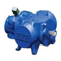
Emerson Vilter VSH Installation, Operation And Service Manual (206 pages)
Single Screw Bare Shaft Compressor
Brand:
Emerson
| Category:
Air Compressor
| Size: 49.27 MB
Table of Contents
Table of Contents
7
Important Message
3
Standard Vilter™ Warranty Statement
4
Standard Vilter™ 5/15 Warranty Statement
5
EC Declaration of Incorporation
6
Table of Contents
7
Table / Figure
12
Table of Contents
12
Additional Important Notes
13
How to Use this Manual
13
Section 1 • General Information
13
System Unit Identification
14
Bare Shaft Refrigeration and Heat Pump Compressor Model Designations
15
Capacity and Volume Control
17
Compressor
17
Section 2 • Theory of Operation
17
Refrigerant and Oil System
18
Refrigerant Flow
18
Oil Life and Oil Flow
18
Figure 2-1. Refrigeration Compressor Unit P&ID (Thermosyphon Oil Cooling with Single Oil Filter Shown)
19
Control System
20
Temperature Elements, Pressure Transmitters and Indicators
20
Critical Application Guidelines
20
Alarm and Shutdown Readings
21
Figure 2-2. Basic Single Screw Compressor System
22
Single Screw Package Requirements
22
Bareshaft Compressor Lifting Points and Weights
23
Delivery Inspection
23
Rigging and Lifting of the Compressor
23
Section 3 • Installation
23
Table 3-1. Bareshaft Compressor Component Weights
23
Table 3-2. Bareshaft Compressor Component Lifting Hole Sizes
23
Figure 3-1. Bareshaft Compressor Lifting Points and Component Weights
24
Figure 3-2. Bareshaft Compressor Assembly Center of Gravity (Models 97-127)
24
Bareshaft Compressor Center of Gravity (Models 291-2101)
25
Figure 3-3. Bareshaft Compressor Assembly Center of Gravity (Models 291-2101)
25
Figure 3-4. Bareshaft Compressor Center of Gravity - Discharge Manifold and Main Compressor Assembly
25
Bareshaft Compressor Center of Gravity (Models 2401-3001)
26
Figure 3-5. Bareshaft Compressor Assembly Center of Gravity (Models 2401-3001)
26
Figure 3-6. Bareshaft Compressor Center of Gravity - Discharge Manifold and Main Compressor Assembly
26
Compressor Inspections Prior to Installation
27
Compressor Mounting
27
Notice on Using Non-Vilter Oils
27
Recommended On-Site Tools
27
Long Term Storage Recommendations
28
Long Term Storage Log
29
Figure 3-7. Stop/Check Valve Orientation
30
Stop/Check Valve Installation
30
Piping
31
Figure 3-8. Maximum Allowable Flange Loads
32
Flange Loads
32
Table 3-3. Maximum Allowable Flange Loads
32
Slide Valve Actuator Installations Instructions
33
Installation
33
Overview
33
Actuator Motor Control Module Calibration Procedure
33
Instrumentation Requirements
34
Pressure
34
Temperature
34
Figure 3-9. Additional Instruments
34
Miscellaneous
35
Testing Refrigeration System for Leaks
35
Ammonia Systems
35
Halocarbon Refrigerant Systems
35
Control System
37
Starting, Stopping and Restarting the Compressor
37
Emergency Shutdown
38
Capacity and Volume Ration Control through Slide Valve Actuators
38
Figure 4-1. Slide Valve Motor Location
38
Notice on Using Non-Vilter Oils
37
Operation
37
Section 4 • Operation
37
Slide Valve Actuator Operation
39
Calibrate Slide Valve Actuators (for Units Using Vission20/20™)
40
Figure 4-2. Actuator Assembly
40
Figure 4-3. Slide Valve Calibration Screen (Vission 20/20)
41
Figure 4-4. Menu Screen and Slide Calibration Button (Vission 20/20)
42
Figure 4-5. Wire Connections for Capacity and Volume Actuators
43
Table 4-1. Command Shaft Rotation Specifications
44
Figure 4-6. Photo-Chopper
45
Calibrate Slide Valve Actuators (for Units Using Compact Logix PLC)
46
Figure 4-7. Actuator Assembly
46
Figure 4-8. Overview, Main Menu and Instrument Calibration Screens (Compact Logix PLC)
48
Figure 4-10. Photo-Chopper
49
Figure 4-9. Slide Calibration Screen (Compact Logix PLC)
49
Compressor Control with Vission20/20™ Micro-Controller (no Slide Operation)
51
Suction Equalizing Line Setup - for VSS/VSM Compressors
52
Stop/Check Valve Operation
53
Table 4-2. Stop/Check Valve Open Positions
53
Maintenance and Service Schedule - for VSS/VSM Unit Only
55
Section 5 • Maintenance/Service
55
Maintenance and Service Schedule - for VSH/VSSH Unit Only
56
Preventive Maintenance, Checks and Services
58
Daily
58
Weekly
58
Monthly
58
Trimonthly
58
Annually
58
Compressor Unit Isolation for Maintenance/Service (Compressors with Slide Valves)
59
Preparation of Unit for Servicing
60
Recommendations When Servicing (Compressors Without Slide Valves)
60
Compressor Unit Leak Check after Servicing
61
Oil Sampling
61
Recommendations
61
Installation of the Oil Sampler Valve
62
Pre-Sampling
62
Sampling Procedure
62
Oil Sample Analysis Report
64
Compressor Replacement
65
Removal
65
Installation
66
Compressor Inspection
67
Compressor Shaft Bearing Clearance Inspections
67
Determine Maximum Applied Force
67
Main Rotor Bearing Axial Clearance Inspection
67
Main Rotor Bearing Radial Clearance Inspection
68
Table 5-3. Maximum Main Rotor Bearing Clearance
68
Gaterotor Bearing Inspection
69
Table 5-4. Maximum Gaterotor Bearing Clearance
69
Gaterotor Inspection
70
A) Gaterotor - Main Housing Shelf Clearance
70
B) Gaterotor Float Measurement
71
Table 5-5. Gaterotor Float
71
C) Gaterotor Backlash Inspection
72
Table 5-6. Backlash Range
73
Important Notes
74
Additional Inspections
74
Post Inspection
74
Gaterotor Assembly Replacement (All Compressors Except VSM 301-701 and VSM 97-127 Compressors)
74
Removal
74
Table 5-7. Gaterotor Tool Kits
74
Installation
75
Gaterotor Assembly Replacement (VSM 301-701 Compressors Only)
78
Removal
78
Installation
78
Gaterotor Assembly Replacement (VSM 97-127 Compressors Only)
80
Removal
80
Installation
80
Gaterotor Disassembly (All Compressors Except VSM 97-127 Compressors)
82
Gaterotor Blade Removal
82
Gaterotor Blade Installation
83
Gaterotor Thrust Bearing Removal
83
Gaterotor Thrust Bearing Installation
83
Gaterotor Roller Bearing Removal
84
Gaterotor Roller Bearing Installation
84
Gaterotor Disassembly (VSM 97-127 Compressors Only)
85
Gaterotor Blade Removal
85
Gaterotor Blade Installation
85
Gaterotor Thrust Bearing Removal
86
Gaterotor Thrust Bearing Installation
86
Gaterotor Roller Bearing Removal
86
Gaterotor Roller Bearing Installation
86
Compressor Shaft Seal Replacement
87
Shaft Seal Assembly
87
Handling Seal Face with Care
87
Compressor Shaft Seal Replacement - for VSS/VSM Units
88
Tools
88
Removal
88
Installation
88
Table 5-8. Shaft Seal Tool Kits
88
Compressor Shaft Seal Replacement - for VSH/VSSH Units
90
Table 5-9. VSH/VSSH Shaft Seals
90
Prior to Shaft Seal Installation
92
Shaft Seal Installation - for Part# 25985Y and 25985Y
93
Shaft Seal Installation - for Part# 28985W and 28985WA
94
Slide Valve Actuator Assembly Replacement
95
Removal
95
Installation
95
Actuator Installation Using Anti-Rotation Bolts
96
Slide Valve Command Shaft Assembly Replacement
97
Removal
97
Installation
97
Liquid Injection Control Valve Station (Danfoss ICF 20-40 Valve Station)
98
Table 5-10. Coils for Solenoid Valves (ICFE)
99
Table 5-11. Parts for Motorized Valve Station (ICF)
99
Main Rotor Assembly
100
Table 5-12. Torque Specifications (Ft-Lbs)
100
Torque Specifications
100
Nord-Lock ® Washers
101
Section 6 • Troubleshooting
103
Table 6-1. Slide Valve Actuator Troubleshooting Guide (1 of 3)
103
Table 6-2. Slide Valve Actuator LED Blink Codes (1 of 2)
106
Using a Torque Wrench Correctly
101
Troubleshooting Guide - General Problems & Solutions
108
Section 7 • Warranty and Parts
111
Warranty Claim Processing
111
On-Site Service Support
113
Remanufactured Bare Shaft Single Screw Compressor Process
113
Explanation of Rebuild Levels
113
Bare Shaft Compressor Description
113
Section 8 • Spare Parts List
115
Gaterotor
118
Shaft Seal
125
Main Rotor
126
Slide Valve Cross Shafts and End Plate
128
End Plate (VSS 2401 - VSS 3001 Only)
130
Slide Valve Carriage Assembly
132
Miscellaneous Frame Components
136
Miscellaneous Frame Components Tubing and Fittings
139
Replacement Tools
142
Replacement Parts
143
Gaterotor Assembly
146
Shaft Seal
148
Main Rotor
149
Slide Valve Cross Shafts and End Plate
150
Slide Valve Carriage Assembly
152
Miscellaneous Frame Components
155
Housing Accessories
157
Replacement Tools
158
Kits
161
Appendix A Torque Specifications
163
Appendix B Vilter Oil
165
Appendix C Vibration Measurements - Single Screw Compressor
169
Appendix D Liquid Injection Valve Setup Instructions and ICM/ICAD Motorized Valve Quick Start Guide
175
Table of Contents
178
Installation
180
Wiring the ICAD
181
ICAD Overview
184
ICAD Programming
185
Troubleshooting
186
The Manual Tool
186
Service Parameters
186
Alarms
187
Tips
187
Common Questions
188
Appendix E Liquid Injection Valve Station ICF 20-40 Installation Guide
189
Appendix F Hand-Held Slide Valve Calibration Tool
201
Related Products
Emerson Vilter VSG
Emerson Vilter VSSG
Emerson VILTER VSR
Emerson Vilter VSS
Emerson Vilter VSM
Emerson Vilter VSSH
Emerson VILTER VSG
Emerson VILTER VSSG
Emerson VSG 301
Emerson Vilter VSG222
Emerson Categories
Controller
Control Unit
Transmitter
Measuring Instruments
Fan
More Emerson Manuals