GE MDS Mercury Series Reference Manual
Wireless ip/ethernet transceiver, covering ap and remote units
Hide thumbs
Also See for MDS Mercury Series:
- Setup manual (4 pages) ,
- Setup manual (4 pages) ,
- Reference manual (76 pages)

Related Manuals for GE MDS Mercury Series


Summary of Contents for GE MDS Mercury Series
- Page 1 MDS Mercury Series Wireless IP/Ethernet Transceiver Covering AP and Remote Units DRAFT MDS 05-4446A01, Rev. 02 AUGUST 2008...
-
Page 3: Table Of Contents
1.1.2 Online Access to Manuals ......................3 1.1.3 Conventions Used in This Manual ....................3 1.2 PRODUCT DESCRIPTION....................4 1.2.1 Model Offerings ..........................6 1.2.2 GE MDS P23 Protected Network (Redundant) Configuration ............7 1.2.3 External GPS PPS Option ......................7 1.3 APPLICATIONS ........................7 1.3.1 Mobile/Fixed Data System ......................8 1.3.2 Wireless LAN ..........................8... - Page 4 2.4 STEP 3 — CONNECT PC TO THE TRANSCEIVER............23 2.5 STEP 4 — REVIEW TRANSCEIVER CONFIGURATION ............ 23 2.5.1 Getting Started .........................23 2.5.2 Procedure ..........................23 2.5.3 Basic Configuration Defaults ....................23 2.6 STEP 5 — CONNECT LAN OR SERIAL DATA EQUIPMENT ..........24 2.7 STEP 6 —...
- Page 5 3.7.3 IEEE 802.1x Device Authentication ..................89 3.7.4 Manage Certificates .........................91 3.8 REDUNDANCY CONFIGURATION (AP ONLY) ..............93 3.9 GPS CONFIGURATION (REMOTE ONLY) ................ 98 3.10 DEVICE INFORMATION MENU ..................100 3.11 PERFORMANCE INFORMATION MENU............... 101 3.12 MAINTENANCE/TOOLS MENU ..................113 3.12.1 Auto Firmware Upgrade Menu (AP Only) ................124 3.13 PERFORMANCE OPTIMIZATION..................
- Page 6 We also became experts in wireless communication standards and system applications worldwide. The result of our efforts is that today, thousands of utilities around the world rely on GE MDS-based wireless networks to manage their most critical assets.
- Page 7 As your wireless needs change you can continue to expect more from GE MDS. We’ll always put the performance of your network above all. Visit us at www.GEmds.com...
- Page 8 These systems will reuse or recycle most of the materials found in this equipment in a sound way. Please contact GE MDS or your supplier for more information on the proper disposal of this equipment.
-
Page 9: Product Overview And Applications
1.1.3 Conventions Used in This Manual ..........3 1.2 PRODUCT DESCRIPTION ............4 1.2.1 Model Offerings ................6 1.2.2 GE MDS P23 Protected Network (Redundant) Configuration ..7 1.2.3 External GPS PPS Option ............. 7 1.3 APPLICATIONS................7 1.3.1 Mobile/Fixed Data System ............8 1.3.2 Wireless LAN ................ - Page 10 Mercury Reference Manual 05-4446A01, Rev. C...
-
Page 11: About This Manual
1.1 ABOUT THIS MANUAL This Reference Manual is one of two publications provided for users of the Mercury Series transceiver system. It contains detailed product information, an overview of common applications, a screen-by-screen review of the menu system, technical specifications, suggested settings for various scenarios, and detailed troubleshooting information. -
Page 12: Product Description
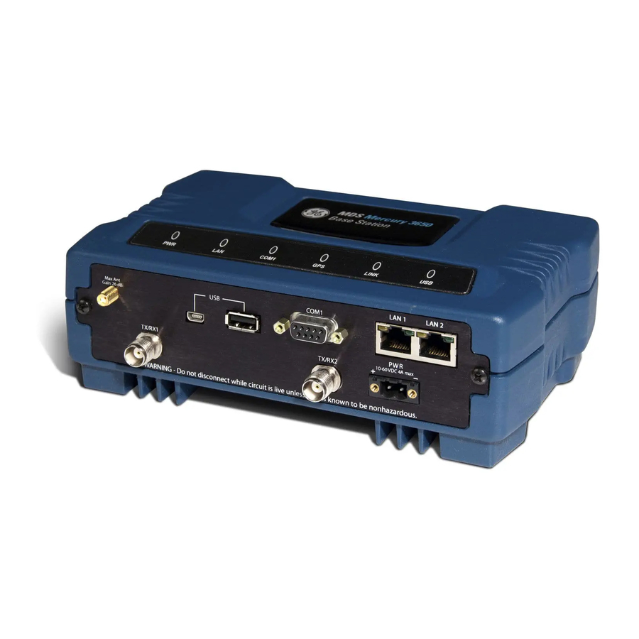
Mercury system the best combination of security, range, and speed of any industrial wireless solution on the market today. Invisible place holder Figure 1-1. The GE MDS Mercury Series Transceiver (Remote unit shown, AP is similar in appearance) - Page 13 Security is not a one-step process that can simply be turned on and for- gotten. It must be practiced and enforced at multiple levels, 24 hours-a-day and 7 days-a-week. See “GE MDS CYBER SECURITY for more information about the transceiver’s secu- SUITE” on Page 16 rity tools.
-
Page 14: Model Offerings
• Built-in GPS Receiver—GPS technology is used for timing and location data. The only external equipment needed for this func- tionality is a GPS antenna (several types are available from GE MDS). 1.2.1 Model Offerings The transceiver comes in two primary models—Access Point and Remote. -
Page 15: Ge Mds P23 Protected Network (Redundant) Configuration
–A it shows a suffix, it is a Remote. –R 1.2.2 GE MDS P23 Protected Network (Redundant) Configuration For mission-critical applications, a Protected Network Station is also offered. This unit incorporates two Access Points, two power supplies, and a switchover logic board that automatically selects between Trans- ceiver A and Transceiver B as the active radio. -
Page 16: Mobile/Fixed Data System
1.3.1 Mobile/Fixed Data System Mercury transceivers support high-speed data communications in a mobile environment. In this application, Remote radios “roam” between different Access Points, providing seamless transitions and continuous coverage throughout a municipal area. Figure 1-3 shows an example of an integrated system employing both mobile and fixed Mercury trans- ceivers. -
Page 17: Point-To-Point Lan Extension
IP format. A Remote transceiver with its serial port connected to a GE MDS serial-based radio, such as the MDS x790/x710, MDS TransNET and others, provides a path for bringing the data from the older radio into the IP/Ethernet environment of a Mercury-based system. -
Page 18: Multiple Protocols And/Or Services
Invisible place holder Serial Device Serial Conn. MDS 4710 Remote Serial Remote Serial MDS 4790 Device NETWORK ROUTER Master MDS 4710 Remote ROUTER Serial Device Serial Conn. Access Point MDS 9710 Remote Remote Serial Serial MDS 9790 Master Device MDS 9710 Remote NMS Control SCADA Host Point... -
Page 19: Wireless Lan With Mixed Services
By using a single radio, the cost of deployment is cut in half. Beyond requiring only one radio instead of two, the biggest cost reduction comes from using half of the required infrastructure at the remote site: one antenna, one feedline, one lightning protector and ancillary hardware. Other cost reductions come from the system as a whole, such as reduced management requirements. -
Page 20: Upgrading Older Wireless Network With Serial Interfaces
Millions of wireless data products have been installed in the last two decades for licensed and license-free operation, many of them manufac- tured by GE MDS. There are several ways that these systems can benefit from incorporating Mercury equipment. The chief advantages are inter- face flexibility (serial and Ethernet in one unit), and higher data throughput. - Page 21 tions. In this case, using high-gain Yagi antennas at each location pro- vides more reliable communications than their counterparts— omnidirectional antennas. Invisible place holder Remote REPEATER Access Point Ethernet Access Remote Point Crossover Cable Remote Remote LAN/WAN Figure 1-9. Typical LAN with a Repeater Link Two transceivers may be connected “back-to-back”...
-
Page 22: Protected Network Operation Using Multiple Access Points
1.4.2 Protected Network Operation using Multiple Access Points Although GE MDS transceivers have a very robust design and have undergone intensive testing before being shipped, it is possible for iso- lated failures to occur. In mission-critical applications, down time can... -
Page 23: Collocating Multiple Radio Networks
protected configuration for the Access Point to greatly reduce the possi- bility of this occurrence. Two or more Access Points can be configured identically, each with its own independent antenna. In this scenario, Remotes will associate with one of the available Access Points. In case of a failure of that AP, the Remotes will quickly associate with another Access Point, re-estab- lishing connectivity to the end devices. -
Page 24: Ge Mds Cyber Security Suite
(See “A Word About Radio Interference” on for more details.) Page 156 1.5 GE MDS CYBER SECURITY SUITE Today, the operation and management of an enterprise is increasingly dependent on electronic information flow. An accompanying concern becomes the cyber security of the communication infrastructure and the security of the data itself. -
Page 25: Accessories
Table 1-2. Security Risk Management Security Vulnerability GE MDS Cyber Security Solution • Unprotected access to configuration via Implement SNMPv3 secure SNMPv1 operation • Intrusion detection Provides early warning via SNMP through critical event reports (unauthorized, logging attempts, etc.) •... - Page 26 Table 1-3. Accessories (Continued) Accessory Description GE MDS Part No. 2-Pin Power Mates with power connector on transceiver. 73-1194A39 Plug Screw terminals provided for wires, threaded locking screws to prevent accidental disconnect. Ethernet RJ-45 Cable assembly used to connect an Ethernet...
-
Page 27: Tabletop Evaluation And Test Setup
TABLETOP EVALUATION AND TEST SETUP 2 Chapter Counter Reset Paragraph Contents 2.1 OVERVIEW ................21 2.2 STEP 1—CONNECT THE ANTENNA PORTS ......21 2.3 STEP 2—CONNECT THE PRIMARY POWER......22 2.4 STEP 3—CONNECT PC TO THE TRANSCEIVER ....23 2.5 STEP 4—REVIEW TRANSCEIVER CONFIGURATION ... 23 2.5.1 Getting Started ................ - Page 28 Mercury Reference Manual 05-4446A01, Rev. C...
-
Page 29: Overview
2.1 OVERVIEW GE MDS recommends that you set up a “tabletop network” to verify the basic operation of the transceivers. This allows experimenting with net- work designs, configurations, or network equipment in a convenient location. This test can be performed with any number of radios. -
Page 30: Step 2-Connect The Primary Power
(RSSI) at each transceiver during the test. In no case should a signal greater than –50 dBm be applied to any transceiver in the test setup. GE MDS recom- mends an RF power output level of +20 dBm from the AP. -
Page 31: Step 3-Connect Pc To The Transceiver
2.4 STEP 3—CONNECT PC TO THE TRANSCEIVER Connect a PC’s Ethernet port to the port using an Ethernet cross- over cable. The LED should light. Alternatively, you can use a serial cable to connect to the port (Figure 2-3 on Page 25). -
Page 32: Step 5-Connect Lan Or Serial Data Equipment
Table 2-1. Basic Configuration Defaults Item Menu Location Default Values/Range Network Name Main Menu>> MDS-Mercury • 1–15 alphanumeric Radio Configuration>> characters Network Name • Case-sensitive; can be mixed case IP Address Main Menu>> 192.168.1.1 Contact your network Network Configuration>> administrator IP Address RF Output Main Menu>>... - Page 33 Invisible place holder LED INDICATOR LAN PORT PANEL COM1 SERIAL PORT RX2 ANTENNA PORT DC POWER INPUT GPS ANTENNA TX/RX1 (10—30 VDC, 2.5A) CONNECTION ANTENNA PORT Figure 2-3. Transceiver Interface Connectors • —Displays the basic operating status of LED INDICATOR PANEL the transceiver.
-
Page 34: Step 6-Check For Normal Operation
2.7 STEP 6—CHECK FOR NORMAL OPERATION Once the data equipment is connected, you can check the transceiver for normal operation. Observe the LEDs on the top cover for the proper indications. In a nor- mally operating system, you will see the following LED indications within 45seconds of start-up: •... - Page 35 Table 2-2. Transceiver LED Functions (Continued) LED Label Activity Indication Internal GPS receiver is synchronized with the satellite network. Blinking AP modem is synchronizing with the GPS timing. Internal GPS receiver is not synchronized with the satellite network. LINK Default state (Access Point) Not transmitting.
- Page 36 Mercury Reference Manual 05-4446A01, Rev. C...
-
Page 37: Embedded Management System
EMBEDDED MANAGEMENT SYSTEM 3 Chapter Counter Reset Paragraph Contents 3.1 MS INTRODUCTION..............31 3.1.1 Differences in the User Interfaces ..........31 3.2 ACCESSING THE MENU SYSTEM .......... 33 3.2.1 Methods of Control ..............34 3.2.2 PC Connection and Log In Procedures ........34 3.2.3 Navigating the Menus ..............38 3.3 BASIC OVERVIEW OF OPERATION........ - Page 38 3.9 GPS CONFIGURATION (REMOTE ONLY)....... 98 3.10 DEVICE INFORMATION MENU..........100 3.11 PERFORMANCE INFORMATION MENU ......101 3.12 MAINTENANCE/TOOLS MENU..........113 3.12.1 Auto Firmware Upgrade Menu (AP Only) .......124 3.13 PERFORMANCE OPTIMIZATION ........127 3.13.1 Proper Operation—What to Look For ...........129 Mercury Reference Manual 05-4446A01, Rev.
-
Page 39: Ms Introduction
Ethernet-based interfaces. Essentially, the same capabilities are avail- able through any of these paths. For support of SNMP software, a set of MIB files is available for down- load from the GE MDS Web site at . An overview of www.GEmds.com... - Page 40 Figure 3-1. Embedded Management System—Top-Level Flowchart Mercury Reference Manual 05-4446A01, Rev. C...
-
Page 41: Accessing The Menu System
Figure 3-2. View of MS with a text-based program— (Console Terminal shown—Telnet has similar appearance) Invisible place holder Figure 3-3. View of the MS with a Browser (Selections at left provide links to the various menus) 3.2 ACCESSING THE MENU SYSTEM The radio has no external controls or adjustments. -
Page 42: Methods Of Control
3.2.1 Methods of Control Access the unit’s configuration menus in one of several ways: • Local Console—This is the primary method used for the exam- ples in this manual. Connect a PC directly to the port COM1 using a serial communications cable and launch a terminal com- munications program such as HyperTerminal (found on most PCs by selecting Start>>Programs>>Accessories>>Communica-... - Page 43 Invisible place holder Transceiver To COM1 or LAN Port (see text) PC Running Terminal Session (115,200 bps, 8N1) Figure 3-4. PC Configuration Setup 1. Connect a serial communications cable between the PC and the Starting a Local unit’s port. If necessary, a cable may be constructed for this Console Session COM1 (Recommended for...
- Page 44 5. Enter your password (default password is ). For security, your admin password keystrokes do not appear on the screen. Press ENTER NOTE: Passwords are case sensitive. Do not use punctuation mark characters. You may use up to 13 alpha-numeric characters. The unit responds with the Starting Information Screen (Figure 3-6).
- Page 45 TIP: You can start a Telnet session on most PCs by selecting: Start>>Pro- . At the command prompt grams>>Accessories>>Command Prompt window, type the word , followed by the unit’s IP address telnet (e.g., ). Press to receive the Telnet log in telnet 10.1.1.168 ENTER screen.
-
Page 46: Navigating The Menus
Invisible place holder Figure 3-7. Log-in Screen when using a Web Browser NOTE: Passwords are case sensitive. Do not use punctuation mark characters. You may use up to 13 alpha-numeric characters. 5. Click . The unit responds with a startup menu screen similar to that shown in Figure 3-8. - Page 47 associated screen where settings may be viewed or changed. In most cases, pressing the key moves the screen back one level in the ESCAPE menu tree. In general, the top portion of menu screens show read-only information (with no user selection letter). The bottom portion of the screen contains parameters you can select for further information, alteration of values, or to navigate to other submenus.
-
Page 48: Basic Overview Of Operation
NOTE: In the menu descriptions that follow, parameter options/range, and any default values are displayed at the end of the text between square brackets. Note that the default setting is always shown after a semicolon: available settings or range; default setting 3.3 BASIC OVERVIEW OF OPERATION 3.3.1 Starting Information Screen Once you have logged into the Management System, the Starting Infor-... - Page 49 • —The unit is has detected one or more alarms that Alarmed have not been cleared. At Remote: • —The unit is looking for an Access Point beacon Scanning signal. • —Unit is adjusting power, timing, and frequency Ranging with an AP. •...
-
Page 50: Main Menu
3.3.2 Main Menu The Main Menu is the entry point for all user-controllable features. The transceiver’s appears at the top of this and all other screens Device Name as a reminder of the unit you are currently controlling. Figure 3-10. Main Menu (AP) (AP screen shown;... -
Page 51: Configuring Network Parameters
• —Status information relating to the radio Performance Information and data layer’s performance in the radio network. (See “PERFORMANCE INFORMATION MENU” on Page 101) • —Tools for upgrading firmware code and test- Maintenance/Tools ing major unit capabilities. (See “MAINTENANCE/TOOLS MENU” on Page 113) 3.4 CONFIGURING NETWORK PARAMETERS... - Page 52 • —Presents a submenu for configuring an AP Location Push Config AP to automatically force connected remotes to receive the AP Locations file from the AP. See “AP Location Push Config Menu” on Page 55 for details. • —Address of SNTP server (RFC 2030) from which SNTP Server the transceiver will automatically get the time-of-day.
- Page 53 VLAN Configuration Menu The VLAN Configuration menu (Figure 3-13) becomes active and vis- ible when you enable on the Network Interface Configura- VLAN Status tion Menu, and you press the Enter key. CAUTION:The VLAN Status parameter must be consistent at both the Access Point and Remote radios in order for data to flow correctly.
- Page 54 Network Interface Configuration Menu—VLAN Items Invisible place holder Figure 3-13. VLAN Configuration Menu • —Defines whether the radio handles Ethernet VLAN Status frames in “extended” 802.1Q mode or in “normal” mode in the Ethernet port. If configured with a trunk port, the Mercury passes all tagged traffic regardless of the VLAN ID.
- Page 55 • —Presents a screen where you can view Data VLAN Subnet Config or set the IP mode and address information (see Figure 3-17 on Page 49). • —Presents a screen where you can view DHCP Server Config (Data) or set DHCP server status and address information for data functions (see Figure 3-16 on Page 49).
- Page 56 A transceiver can provide automatic IP address assignments to other IP DHCP Server devices in the network by providing DHCP (Dynamic Host Configura- Configuration (Data and Mgmt) tion Protocol) services. This service eliminates setting an individual device IP address on Remotes in the network, but it requires some plan- ning of the IP address range.
- Page 57 Invisible place holder Figure 3-16. DHCP Server Configuration (Data) Menu • —Enable/Disable the response to DHCP DHCP Server Status requests to assign an IP address. [ Disabled/Enabled; Disabled • —IP netmask to be assigned along with the IP DHCP Netmask address in response to a DHCP request.
- Page 58 • —Defines the source of this device’s IP address. IP Address Mode Only static IP addressing mode is available when VLAN Status is enabled [ Static; Static • —The IPv4 local IP address. [ IP Address 192.168.1.1 • —The IPv4 local subnet mask. This value is used IP Netmask when the radio attempts to send a locally initiated message, from either the terminal server or the management process.
-
Page 59: Ethernet Port Configuration Menu
• —The IPv4 local subnet mask. This field is Static IP Netmask unnecessary if DHCP is enabled. [ 255.255.0.0 • —The IPv4 address of the network gateway Static IP Gateway device, typically a router. This field is unnecessary if DHCP is enabled. -
Page 60: Bridge Configuration
• —Allows enabling/disabling filtering and Ethernet Filtering Config specifying of Ethernet addresses. Ethernet Filtering Configuration Menu Invisible place holder Figure 3-20. Ethernet Filtering Configuration Menu • —Activates Ethernet filtering. Enable Filtering enabled, disabled; disabled • —Ethernet address fields. When filtering is Address 1, 2, 3, 4 enabled, the Mercury only accepts traffic on its Ethernet port from the configured addresses. -
Page 61: Snmp Agent Configuration
• —View/set spanning tree hello time. This Bridge Hello Time parameter affects how often the bridge sends a spanning tree Bridge Protocol Data Unit (BPDU). [ 1-10 seconds; 2 seconds • —View/set spanning tree forwarding delay. Bridge Forward Delay Affects how long the bridge spends listening and learning after initialization. - Page 62 Invisible place holder Figure 3-22. SNMP Server Configuration Menu This menu provides configuration and control of vital SNMP functions. • —SNMP community name with Read Community String SNMPv1/SNMPv2c read access. This string can contain up to 30 alpha-numeric characters. • —SNMP community name with Write Community String SNMPv1/SNMPv2c write access.
-
Page 63: Ap Location Push Config Menu
• —This specifies which version of SNMP is used to Trap Version encode the outgoing traps. The choices are v1_traps v2_traps . When is selected, v2-style traps are sent, v3_traps v3_traps but with a v3 header. [ v1_traps, v2_traps, v3_traps •... - Page 64 • —Name of the AP Locations file on the AP Locations Filename server. [ any valid filename string; ap_locations.txt • —A setting to force connected Auto AP Location Download remotes to download immediately the AP Locations file on the AP. Remotes that associate to an AP with this feature will also download the file.
-
Page 65: Sntp Server Configuration
• —Name of a grouping of Access Points. A Remote con- GROUP figured with enabled does not disable its Eth Follows Association wired port when moving between APs of the same group.This is useful when two or more APs are on the same subnet. •... -
Page 66: Radio Configuration
Invisible place holder Figure 3-25. SNTP Server Entry (on Network Configuration Menu) When is selected (item H), the area to the right of the param- SNTP Server eter becomes active, allowing you to enter a valid SNTP server address. Press the Return key to make the address entry active. 3.5 RADIO CONFIGURATION There are two primary layers in the transceiver network—radio and data. - Page 67 Figure 3-27. Radio Configuration Menu (From Remote Unit) • —The user-defined name for the wireless network. Network Name Any 40 character string; MDS-Mercury • (AP Only)—Sets/displays RF power output level Transmit Power in dBm. This setting should reflect local regulatory limitations and losses in antenna transmission line.
- Page 68 Frequency Control Menu The items shown on this menu vary depending on the Frequency Mode Selection ( ). Examples Single Channel Static Hopping Hopping w/Hand-offs of all three screens are provided below, followed by a description of the menu items. Invisible place holder Figure 3-28.
- Page 69 Invisible place holder Figure 3-30. Frequency Control Menu (Hopping w/Hand-offs Freq. Mode [Remote only]) • —The unit can operate on one selected fre- Frequency Mode quency or frequency hop. Remotes have the option of using a static hopping configuration or using the AP locations file to select an AP and perform hand-offs.
- Page 70 Table 3-1. Channel/Frequency Allocations Channel 1.75 MHz B/W 3.5 MHz B/W 921.400000 923.400000 925.200000 927.000000 • —View/set the radio’s RF operating bandwidth. RF Bandwidth Radios are factory-configured for either 1.75 MHz or 3.5 MHz maximum bandwidth. Determine the factory configuration of a radio by viewing the “CONFIG”...
- Page 71 using Offset 0. The hand-off configured Remote, using its AP Locations file, may connect to AP1, AP2, or AP3. The Remote does this by determining the Offset for each AP, then configur- ing its radio. AP 1 AP 2 AP 3 Pattern A Pattern A Pattern A...
- Page 72 hand-off parameters for Remote transceivers and explains how they operate under different signal conditions. Table 3-2. Remote Hand-Off Parameters Strict Strict Strict Signal and Signal, Dis- Distance Connection Signal Distance tance, and Bearing Description The Remote The Remote will The Remote Operates the Operates the always chooses...
- Page 73 Advanced Configuration Menu Invisible place holder Figure 3-31. Advanced Configuration Menu • —Enables automatic selection of modulation Adaptive Modulation and FEC rate based on SNR. [ enabled, disabled; enabled • —A number of decibels of SNR added to the Protection Margin minimum SNR required for a given modulation and FEC rate.
- Page 74 • —Enables the Automatic Repeat Request function. enable, disable; enabled • —The maximum number of blocks to send ARQ Window Size before receiving an acknowledgement. [ 1–1024; 512 • —ARQ is applied to payload data in blocks of this ARQ Block Size size.
-
Page 75: Serial Port Configuration
For example, the third SNR value in Column D is 11.4 dB (8.4 + 3 = 11.4 dB), and the third SNR value in Column E is 17.1 (11.1 + 3 + 3 = 17.1 dB). Note that with a Hysteresis Margin of 3 dB, there is an overlap of 3 between the Max SNR of one modulation and the Min SNR of the next higher modulation. - Page 76 NOTE: To restore the port to support Management System COM1 services, connect a terminal to the port, select the proper baud rate (115,200 is default), and enter an escape sequence ( ) to reset it to the console mode. There is a configuration parameter for the console baud rate another parameter for the .
- Page 77 Data Buffering connect EIA-232 serial devices to the transceiver, review these parame- ters carefully. Serial Configuration Wizard GE MDS recommends the Serial Configuration Wizard, available through the , for configuration of the serial Serial Port Configuration Menu terminal services. The wizard uses a step-by-step process, eliminates possible conflicting settings, and streamlines complex configurations.
- Page 78 Figure 3-33. Serial Configuration Wizard • —Tool for configuring serial ports using a Begin Wizard step-by-step process. • —Displays all setable options. Varies View Current Settings depending on the selected IP protocol. Configuring for UDP Invisible place holder Point-to-Multipoint Figure 3-34. UDP Point-to-Multipoint Menu Use UDP point-to-multipoint to send a copy of the same packet to mul- tiple destinations, such as in a polling protocol.
- Page 79 • —Receive IP data from this source and pass it RX IP Port through to the connected serial device. The port number must be used by the application connecting to local TCP or UDP socket. [ Any valid IP port; 30010 •...
- Page 80 Invisible place holder Figure 3-35. UDP Point-to-Point Menu Use UDP point-to-point configuration to send information to a single Configuring for UDP device. Point-to-Point • —Enable/Disable the serial data port. Status • —UDP Point-to-Point. This is the type of IP port IP Protocol offered by the transceiver’s serial device server.
- Page 81 • —Save and execute changes Commit Changes and Exit Wizard made on this screen (shown only after changes have been entered). Configuring for TCP Invisible place holder Mode Figure 3-36. TCP Client Menu (Remote) • —Enable/Disable the serial data port. Status •...
- Page 82 • —Maximum amount of characters that the Remote Buffer Size end buffers locally before transmitting data through the serial port. [ 1–255; 255 • —A measurement representing the Inter-Frame Packet Delay end of a message, measured in tenths of a second. default = 1 (that is, 1/10th of a second) •...
- Page 83 • —Save and execute changes Commit Changes and Exit Wizard made on this screen (shown only after changes have been entered). IP-to-Serial Application Example You must choose UDP or TCP to establish communications. This depends on the type of device you are communicating with at the other end of the IP network.
- Page 84 Point-to-Point Serial-to-Serial Application Example Once you have configured the transceivers, they begin processing data presented at the ports. Data presented at the Access Point’s port is packetized and sent via UDP to the Remote. Upon receiving the packet, the Remote strips the data out of the UDP packet and sends it out port.
- Page 85 Access Point, stripped, and sent out the Access Point’s port (see Figure 3-40, Table 3-6, Figure 3-41, and Figure 3-42 on Page 78). Invisible place holder 192.168.0.2 192.168.0.10 192.168.0.1 EIA-232 Remote 192.168.0.3 EIA-232 EIA-232 Access Point Terminal Remote or Computer EIA-232 192.168.0.4 Remote...
- Page 86 Figure 3-41. Serial Port Configuration—Access Point Figure 3-42. Radio Serial Port Configuration—Remote Mixed Modes In this example, the TCP mode does not involve the Access Point. Thus, the transceiver in a single network can run in both modes at the same time.
- Page 87 • Communicate with RTU A by Telneting to Remote 1, port 30010. Operation and Data Flow • Communicate with RTU B by Telneting to Remote 2, port 30010. • Communicate with RTUs C and D by sending and receiving data from the Access Point’s port.
-
Page 88: Modbus / Tcp Server Configuration
Table 3-7. Serial Port Application Configuration (Continued) Transceiver Location Menu Item Setting Receive on Port 30010 Receive on Address 224.254.1.1 (The multicast IP address used for the AP’s Send To Address above) 3.6 MODBUS / TCP SERVER CONFIGURATION Modbus is a serial communications protocol developed by Schneider Electric (Modicon) for communication between programmable logic controllers (PLCs), remote terminal units (RTUs) and other industrial electronic devices. - Page 89 management system. Follow the steps below to proceed with Modbus/TCP configuration. 1. From the Serial Configuration Wizard opening screen (Figure 3-44 on Page 81), select to begin the wizard. Invisible place holder Figure 3-44. Configuration Wizard Opening Screen 2. Choose the IP protocol you wish to use (TCP, UDP, or Mod- bus/TCP) by selecting the appropriate letter from the menu.
- Page 90 Figure 3-46. Modbus/TCP Server Listening Port 4. On the next screen (Figure 3-47), press to change the Modbus serial format, then press the space bar to toggle between the avail- able formats ( ). Press to enter the MODBUS/RTU MODBUS/ASCII Modbus serial timeout value in milliseconds.
- Page 91 5. When the next screen appears (Figure 3-48), press to select the desired data baud rate and to select the data byte format. Press continue. Figure 3-48. Select Data Baud Rate and Byte Format 6. The screen shown in Figure 3-49 appears next.
- Page 92 Invisible place holder Figure 3-50. Serial Port Status Screen 8. Review all settings on the summary screen shown in Figure 3-51. If all settings are correct, press to confirm and exit the wizard. If not, select the letter of the item(s) you wish to change. Invisible place holder Figure 3-51.
-
Page 93: Security Configuration Menu
3.7 SECURITY CONFIGURATION MENU The transceiver’s security features are grouped into four major catego- ries and are accessible from the Security Configuration Menu (see Figure 3-52). These categories are: —Contains settings for controlling access to the radio Device Security itself for configuration and management. —Controls how and when radios communicate with Wireless Security each other, as well as how data traffic is handled. -
Page 94: Device Security Menu
3.7.1 Device Security Menu The Device Security Menu (Figure 3-53) controls how the radios can be accessed either locally or remotely for configuration and management. Invisible place holder Figure 3-53. Device Security Menu • —Controls Telnet access to the transceiver’s man- Telnet Access agement system. -
Page 95: Wireless Security Menu
User Passwords Menu Invisible place holder Figure 3-54. User Passwords Menu To change the Administrator or Guest password, select the appropriate menu item (A or B). A flashing cursor appears to the right. From here, type the new password, which can be any alpha-numeric string up to 13 characters long. - Page 96 Invisible place holder Figure 3-55. Wireless Security Menu • —View/set the device’s authentication method. Device Auth Mode None, Local, IEEE 802.1X; None • —Controls the over-the-air payload data’s Data Encryption AES-128 bit encryption. [ enable, disable; disabled • —View/set the phrase used to generate encryp- Encryption Phrase tion keys when encrypting over-the-air payload.
-
Page 97: Ieee 802.1X Device Authentication
3.7.3 IEEE 802.1x Device Authentication This section covers the configuration needed for the radios to access the IEEE 802.1x device authentication server, which provides Device Level Security and for Wireless Access Security. GE MDS does not provide the server software. Operation of Device Authentication Device authentication forces the radio to authenticate before allowing user traffic to traverse the wireless network. - Page 98 Each Access Point and Remote radio must be identified/recognized by the device authentication server through the Common Name (Serial number) and IP address entries. NOTE: Consult your network administrator for assistance in configu- ration, or for help with other issues that may arise. To activate device authentication, select and set Device Auth Method...
-
Page 99: Manage Certificates
RADIUS Configuration Menu Invisible place holder Figure 3-57. Radius Configuration Menu • —The IP address of the authentication Auth Server Address server. [ any valid IP address; 0.0.0.0 • —The UDP Port of the authentication server. Auth Server Port 1812, 1645, 1812 •... - Page 100 Invisible place holder Figure 3-58. Manage Certificates Menu • — —IP address of the com- (Telnet/Terminal only) TFTP Host Address puter on which the TFTP server resides. This same IP address is used in other screens/functions (reprogramming, logging, etc.). Changing it here also changes it for other screens/functions. Any valid IP address;...
-
Page 101: Redundancy Configuration (Ap Only)
Invisible place holder Figure 3-59. Transfer Options Menu • —The time the client radio will wait for a response TFTP Timeout from the server before ending the transfer. • —The amount of data sent in each TFTP packet. TFTP Block Size 3.8 REDUNDANCY CONFIGURATION (AP ONLY) For operation in protected (redundant) mode, an AP must be in a Pack-... - Page 102 Invisible place holder Figure 3-60. Redundancy Configuration Menu (AP Only) • —Enable/disable redundancy switcho- Redundancy Configuration ver for AP. [ enabled, disabled; disabled • —This selection opens a submenu Network Event Triggers (Figure 3-61 on Page 95) where you can set/view the trigger sta- tus for Network Events.
- Page 103 Network Event Triggers Menu Invisible place holder Figure 3-61. Network Events Triggers Menu • —This setting determines whether or not a Network Interface Error network interface error will cause redundancy switchover. enabled, disabled; disabled Radio Event Triggers Invisible place holder Figure 3-62.
- Page 104 Hardware Event Triggers Invisible place holder Figure 3-63. Hardware Event Triggers • —This setting determines whether or not an Init/Hardware Error initialization or hardware error results in a redundancy switcho- ver. [ enabled, disabled; disabled Redundancy Configuration Options Menu Use this menu (Figure 3-64) to set the thresholds for the Lack of Asso- ciated Remotes and Packet Receive Errors.
- Page 105 • —This selection opens a Packet Receive Errors Exceeded Threshold submenu (Figure 3-66 on Page 97) where you can view or change the maximum allowable number of receive errors. Lack of Associated Remotes Exceeded Invisible place holder Threshold Menu Figure 3-65. Lack of Associated Remotes Exceeded Threshold Menu •...
-
Page 106: Gps Configuration (Remote Only)
• —Select this item to change the maxi- Maximum Receive Errors mum allowable number of receive errors. When the number of errors exceeds this number, a redundancy switchover occurs. 0-1000; 500 3.9 GPS CONFIGURATION (REMOTE ONLY) This menu allows you to view or set important parameters for the built-in Global Positioning System (GPS) receiver in the Mercury Remote. - Page 107 Invisible place holder Figure 3-68. GPS Streaming Configuration Menu • —Seconds between GGA string outputs, the satellite GGA Polling fix information. • —Seconds between GLL string outputs, the latitude GLL Polling and longitude information. • —Seconds between GSA string outputs, the overall GSA Polling satellite data.
-
Page 108: Device Information Menu
3.10 DEVICE INFORMATION MENU Figure 3-69 shows the menu that displays basic administrative data on the unit to which you are connected. It also provides access to user-spe- cific parameters such as date/time settings and device names. Figure 3-69. Device Information Menu •... -
Page 109: Performance Information Menu
• —Fields used at user’s discretion for general Device Names administrative purposes. The Device Name field is shown on all menu screen headings. (See Figure 3-70 on Page 101) NOTE: The transceivers do not save time and date information when power is removed. - Page 110 Invisible place holder Figure 3-71. Performance Information Menu • —Access this menu for managing the unit’s opera- Event Log tional activities log. (See Figure 3-74 on Page 104 for details.) • —Multiple radio and network operating statis- Packet Statistics tics. (See Figure 3-76 on Page 106 for details.) •...
- Page 111 Invisible place holder Figure 3-72. Performance Trend Screen Invisible place holder Figure 3-73. Bridge Status Menu 05-4446A01, Rev. C Mercury Reference Manual...
- Page 112 Event Log Menu Invisible place holder Figure 3-74. Event Log Menu • —Shows active alarms (if any) reported by the Current Alarms transceiver. • —Displays a log of radio events arranged by event View Event Log number, date, and time. (Example shown in Figure 3-75 on Page 105).
- Page 113 View Event Log Invisible place holder Menu Figure 3-75. View Event Log Menu The transceiver’s microprocessor monitors many operational parame- ters and logs them. Events are classified into four levels of importance, which are described in Table 3-8. Some of these events result from a condition that prevents normal operation of the unit.
- Page 114 Invisible place holder Figure 3-76. Packet Statistics Menu • —Data packets received by this unit. Packets Received • —Data packets sent by this unit. Packets Sent • —Data bytes received by this unit. Bytes Received • —Data bytes sent by this unit. Bytes Sent •...
- Page 115 GPS Status Menu Invisible place holder Figure 3-77. GPS Status Menu • —The serial number of the GPS unit in the GPS Serial Number radio. • —The firmware version running on the GPS Firmware Version GPS chip. • —Indicates whether or not the unit has Satellite Fix Status achieved signal lock with the minimum required number of GPS satellites.
- Page 116 GPS Information Invisible place holder Menu Figure 3-78. GPS Information Menu Wireless Network Status Menu The Wireless Network Status screen provides information on a key operating process of the transceiver—the association of the Remote with the Access Point. The following is a description of how this process takes place and is monitored by the menu system.
- Page 117 Invisible place holder Figure 3-79. Wireless Network Status Menu (AP) Invisible place holder Figure 3-80. Wireless Network Status Menu (Remote) • —Displays the overall operating condition of the Device Status transceiver. [ Operational, Alarmed • (AP Only)—Shows the number of Remote Associated Remotes transceivers currently associated with the AP.
- Page 118 • (Remote Only)—Displays the current state of Connection Status the wireless network communication as follows: Scanning, Rang- . A complete ing, Connecting, Authenticating, Associated, Alarmed explanation of these operating states is provided in Table 4-3 on Page 138. • —Displays the Ethernet MAC address of Current AP Eth Address the current AP.
- Page 119 Invisible place holder Figure 3-83. Remote Database Details Menu (AP) Internal Radio Status Menu (Remote Only) Invisible place holder Figure 3-84. Internal Radio Status (Remote Only) • —Indicates whether or not the Remote station Connection Status has associated with an AP. [ Associated, Scanning, Ranging, Con- necting, Authorizing •...
- Page 120 • —Shows average signal-to-noise-ratio (SNR) of Average SNR received signals, displayed in dB. This is a measurement of the quality of the incoming signal. It is possible for incoming sig- nals to be strong, yet be affected by interference or other noise, resulting in a low SNR.
-
Page 121: Maintenance/Tools Menu
3.12 MAINTENANCE/TOOLS MENU In the course of operating your network, you may wish to upgrade trans- ceiver firmware to take advantage of product improvements, work with configuration scripts, conduct “ping” tests of your system, or reset oper- ating parameters to factory default settings. All of these tasks are per- formed using the Maintenance/Tools Menu (Figure 3-86). - Page 122 Invisible place holder Figure 3-87. Firmware Versions Menu Figure 3-88. Telnet Utility Menu • —The IP address of the target device. Host Address • —Connect to the target device at the host address. Connect Reprogramming Menu The factory sometimes offers upgrades to the transceiver firmware. Loading new firmware into the unit will not alter any privileges pro- vided by Authorization Keys and does not require you to take the trans- ceiver off-line until you want to operate the unit with the newly installed...
- Page 123 NOTE: Always read the release notes for downloaded firmware. These notes contain important information on compatibility and any special steps needed for proper installation. All units and versions have two resident images. Version 1.4.4 had two .mpk files, one for the Access Point and one for the Remote. As of ver- sion 2.1.0, there is only one .mpk file which you can use with both Access Points and Remotes.
- Page 124 (See “Starting Information Screen” Starting Information Screen on Page 40.) A TFTP server is available on the GE MDS Web site at: www.GEmds.com/Resources/TechnicalSupport/ TIP: If you do not know your computer’s address on a Windows PC, you can use the...
- Page 125 Invisible place holder TRANSCEIVER LOCAL WINDOWS PC WITH CONFIG. FILES PORT IP ADDRESS: 172.0.0.B IP ADDRESS: 172.0.0.A INITIATE UPLOAD FROM HERE Figure 3-90. Firmware Upgrade Setup—Option 1 (TFTP Server and Firmware File on Same CPU) Invisible place holder REMOTE PC W/FIRMWARE FILES TFTP HUB/LAN/WAN/MAN...
- Page 126 1. Launch a TFTP server on a PC connected either directly or via a LAN to the Ethernet port ( ) of the radio. Point the server towards the directory containing the firmware image file. 2. Connect to the Management System by whichever means is conve- nient: browser or Telnet via the , or Terminal emulator via the port.
- Page 127 Table 3-9. Common Errors During TFTP Transfer (Continued) Error Message Likely Cause/Corrective Action Flash Error Flash memory error. Contact factory for assistance. Bad CRC Cyclic Redundancy Check reporting a corrupted file. Attempt to re-load, or use a different file. Version String Mismatch Invalid file detected.
- Page 128 Invisible place holder Figure 3-92. Configuration Scripts Menu • —IP address of the computer on which the TFTP Host Address TFTP server resides. [ Any valid IP address • —Name of file containing this unit’s configura- Config Filename tion profile that will be transferred to the TFTP server. The con- figuration information is in plain-text ASCII format.
- Page 129 Modify the configura- tion files using a text editor or an automated process. (These applica- tions are not provided by GE MDS). We recommend that you review and update the following parameters for each individual unit.
- Page 130 Ping Utility Menu Invisible place holder Figure 3-93. Ping Utility Menu • —Address to send a Ping. [ Address to Ping Any valid IP address • —Number of Ping packets to be sent. Count • —Size of each Ping data packet (bytes). Packet Size •...
- Page 131 Authorization Codes Invisible place holder Figure 3-95. Authorization Codes Menu • —For entering an Authorization Key into the Authorization Key transceiver’s non-volatile memory. • —List of the transceiver’s authorized fea- Authorized Features tures. Each item shows according to the set- enabled disabled tings allowed by the Authorization Key entered into the radio.
-
Page 132: Auto Firmware Upgrade Menu (Ap Only)
Invisible place holder Figure 3-96. Reset to Factory Defaults Action (Note challenge question at bottom of screen) 3.12.1Auto Firmware Upgrade Menu (AP Only) Invisible place holder Figure 3-97.Auto Firmware Upgrade Menu • —Causes all of the Remotes associated to this Firmware Upgrade AP to read the AP’s specified (by ) firmware... - Page 133 NOTE: To use the Auto Upgrade/Reboot feature, both the AP and Remotes must already be running version 2.1.0 or newer firm- ware. • —Specifies the firmware version that the Firmware for Upgrade Remotes should download, if they do not already have it. Radio Test Menu Using this menu, you can manually key the radio transmitter for perfor- mance checks and set several parameters that will be used when the...
- Page 134 • —Sets/displays the transmitter’s power set- Test Transmit Power ting. Make a numerical entry within the allowable range. -30 to +30 dBm • —Sets/displays the radio’s test channel number. Test Channel Make a numerical entry within the allowable range. 0-13; 0 •...
-
Page 135: Performance Optimization
Figure 3-100. Spectrum Analyzer Display 3.13 PERFORMANCE OPTIMIZATION After checking basic radio operation, you can optimize the network’s performance. The effectiveness of these techniques varies with the design of your system and the format of the data being sent. There are two major areas for possible improvement—the radio and the data network. - Page 136 Table 3-11. Recommended Settings for Common Scenarios For Fixed Locations, where best combination of range and throughput is desired. Remote Units Notes Network User User AP and Remote must match. Name discretion discretion Transmit Power In most cases, power can be set to +30 dBm (AP)/ and left alone.
-
Page 137: Proper Operation — What To Look For
For Optimal Sensitivity (Trades off throughput for best possible sensitivity. AP more susceptible to interference) Remote Units Notes Radio Receive Sets AP receiver for highest gain. Configuration Power When Heavy Interference Exists at AP (Trades off range for robustness in the face of interference) Remote Units Notes... - Page 138 Table 3-12. Mercury Remote Transceiver (Continued) (Performance Information>>Internal Radio Status Menu) Name Target Value Notes Strong signal (bench A low SNR may be caused by (Signal-to-Noise Ratio) setting): 25-28 dB noise or interfering signals. Operational: 3-30 dB Typ. System: 10-20 dB TX Freq.
- Page 139 • Use connectionware—The use of connectionware in the mobile lap- tops is highly recommended for better operation of a mobile data system. GE MDS provides connectionware from one of the vendors in this market. Contact your factory representative for details.
- Page 140 Mercury Reference Manual 05-4446A01, Rev. C...
-
Page 141: Troubleshooting & Radio Measurements
TROUBLESHOOTING & RADIO MEASUREMENTS 4 Chapter Counter Reset Paragraph Contents 4.1 TROUBLESHOOTING ............135 4.1.1 Interpreting the Front Panel LEDs ..........135 4.1.2 Troubleshooting Using the Embedded Management System ...136 4.1.3 Using Logged Operation Events ..........139 4.1.4 Alarm Conditions ...............140 4.1.5 Correcting Alarm Conditions .............141 4.1.6 Logged Events ................142 4.2 RADIO (RF) MEASUREMENTS.......... - Page 142 Mercury Reference Manual 05-4446A01, Rev. C...
-
Page 143: Troubleshooting
If problems cannot be resolved using the guidance provided here, review Factory Assistance the GE MDS web site’s technical support area for recent software/firm- ware updates, general troubleshooting help, and service information. Additional help is available through our Technical Support Department. -
Page 144: Troubleshooting Using The Embedded Management System
resolving common system difficulties using the LEDs, and Table 4-2 on Page 137 provides other simple techniques. Table 4-1. Troubleshooting Using LEDs—Symptom-Based Symptom Problem/Recommended System Checks PWR LED does not a. Voltage too low—Check for the proper supply voltage at turn on the power connector. - Page 145 Table 4-2. Basic Troubleshooting Using the Management System Symptom Problem/Recommended System Checks Cannot access the a. Connect to unit via Telnet or Web browser. MS through COM1 b. Disable the serial mode for COM1 (Serial Gateway Configuration>>Com1 Serial Data Port>>Status>>Disabled). Or, if you know the unit’s data configuration: a.
- Page 146 connect to the Management System, see “STEP 3—CONNECT PC TO THE TRANSCEIVER” on Page Starting Information Screen (See Starting Information Screen on Page The Management System’s home page provides some valuable bits of data. One of the most important is the field.
-
Page 147: Using Logged Operation Events
Packet Statistics Menu (See Packet Statistics Menu on Page 105) This screen provides detailed information on data exchanges between the unit being viewed and the network through the wireless and the Ethernet (data) layers. These include: Wireless Packet Statistics • Packets received •... -
Page 148: Alarm Conditions
permanent memory (Flash memory) until cleared by user request. Table 4-4 summarizes these classifications. Table 4-4. Event Classifications Level Description/Impact Storage Alarms Transceiver has detected one or Flash more alarm conditions Memory Informational Normal operating activities Flash Memory Temporary Transient conditions or events Informational Minor Does not affect unit operation... -
Page 149: Correcting Alarm Conditions
Table 4-5. Alarm Conditions (Alphabetical Order) (Continued) Alarm Condition Reported Event Log Entry SNMP Trap EVENT_RSSI_CAL RSSI Not Calibrated rssiCal(9) EVENT_SYSTEM_ERROR* System Error Cleared; systemError(16) Please Reboot EVENT_TFTP_CONN TFTP connectivity tftpConnection(73) achieved EVENT_TFTP_ERR Attempted TFTP tftpConnFailed(79) connection failed * User can correct condition, clearing the alarm. 4.1.5 Correcting Alarm Conditions (See Event Log Menu on Page... -
Page 150: Logged Events
4.1.6 Logged Events (See Event Log Menu on Page 104) The following events allow the transceiver to continue operation and do not make the LED blink. Each is reported through an SNMP trap. The left hand column, Event Log Entry, is what shows in the Event Log. Table 4-7. -
Page 151: Radio (Rf) Measurements
Table 4-7. Non-Critical Events—Alphabetical Order (Continued) Event Log Entry Severity Description SNR Within threshold/Below INFORM Self explanatory threshold System Bootup (power on) INFORM Self explanatory Telnet Access Locked for MAJOR Self explanatory 5 Min Telnet User Logged MAJOR Self explanatory Out/Logged In User Selected Reboot MAJOR... -
Page 152: Antenna Aiming-For Directional Antennas
Record the current transmitter power output level, then set it to 30 dBm for the duration of the test to provide an adequate signal level for the directional wattmeter. Procedure 1. Place a directional wattmeter between the antenna connector and the antenna system. - Page 153 strength. The transceiver has a built-in received signal strength indicator (RSSI) that can tell you when the antenna is in a position that provides the optimum received signal. RSSI measurements and Wireless Packet Statistics are based on mul- tiple samples over a period of several seconds. The average of these measurements is displayed by the Management System.
- Page 154 7. If the RSSI peak results in an increase in the Wireless Packets Dropped and Received Error, the antenna may be aimed at an undes- ired signal source. Try a different antenna orientation. End of procedure. Mercury Reference Manual 05-4446A01, Rev. C...
-
Page 155: Planning A Radio Network
PLANNING A RADIO NETWORK 5 Chapter Counter Reset Paragraph Contents 5.1 INSTALLATION PLANNING ............ 149 5.1.1 General Requirements ..............149 5.1.2 Site Selection ................151 5.1.3 Terrain and Signal Strength ............151 5.1.4 Antenna & Feedline Selection ...........151 5.1.5 How Much Output Power Can be Used? ........155 5.1.6 Conducting a Site Survey ............155 5.1.7 A Word About Radio Interference ..........156 5.2 dBm-WATTS-VOLTS CONVERSION CHART...... - Page 156 Mercury Reference Manual 05-4446A01, Rev. C...
-
Page 157: Installation Planning
5.1 INSTALLATION PLANNING This section provides tips for selecting an appropriate site, choosing an antenna system, and reducing the chance of harmful interference. 5.1.1 General Requirements There are three main requirements for installing a transceiver—ade- quate and stable primary power, a good antenna system, and the correct interface between the transceiver and the data device. - Page 158 mounting location that provides easy access to the connectors on the end of the radio and an unobstructed view of the LED status indicators. VIEW 6.75″ (17.15 cm) 1.4″ FRONT (3.56 cm) VIEW Figure 5-2. Transceiver Dimensions Invisible place holder Invisible place holder 8 5/8″...
-
Page 159: Site Selection
5.1.2 Site Selection Suitable sites should provide: • Protection from direct weather exposure • A source of adequate and stable primary power • Suitable entrances for antenna, interface, or other required cabling • An antenna location that provides a transmission path that is as unobstructed as possible in the direction of the associated sta- tion With the exception of the transmission path, you can quickly determine... - Page 160 Antennas The radio equipment can be installed with a number of antennas. The exact style used depends on the physical size and layout of a system. Contact your factory representative for specific recommendations on antenna types and hardware sources. In general, an omnidirectional antenna (Figure 5-4) is used at the Access Points and mobile Remote stations.
- Page 161 Invisible place holder Figure 5-5. Typical Yagi Antenna (mounted to mast) Diversity Reception (RX2) Antenna Port Reserved for future functionality. Future releases of the product will allow you to connect a second antenna to the transceiver for space diver- sity reception. GPS Antennas A number of GPS antennas (both active and passive) are available for use with the transceivers.
- Page 162 4.00 dB The tables below outline the minimum lengths of RG-214 coaxial cable that must be used with common GE MDS omnidirectional antennas in order to maintain compliance with FCC maximum limit of +36 dBi. If other coaxial cable is used, make the appropriate changes in loss figures.
-
Page 163: How Much Output Power Can Be Used
NOTE: There is no minimum feedline length required when a 6 dBi gain or less antenna is used, as the EIRP will never exceed 36 dBm which is the maximum allowed, per FCC rules. Only the manufacturer or a sub-contracted professional installer can adjust the transceiver’s RF output power. -
Page 164: A Word About Radio Interference
reported RSSI value. (See “Antenna Aiming—For Directional for details.) If you cannot obtain adequate Antennas” on Page 144 signal strength, it might be necessary to mount the station antennas higher, use higher gain antennas, select a different site, or install a repeater station. - Page 165 chance of causing unnecessary interference to nearby systems. If you are not familiar with these interference-control techniques, con- tact your factory representative for more information. Calculating System Gain To determine the maximum allowable power setting of the radio, per- form the following steps: 1.
-
Page 166: Dbm-Watts-Volts Conversion Chart
5.2 dBm-WATTS-VOLTS CONVERSION CHART Table 5-4 is provided as a convenience for determining the equivalent voltage or wattage of an RF power expressed in dBm. Table 5-4. dBm-Watts-Volts conversion—for 50 ohm systems dBm V dBm V dBm mV dBm µV 100.0 200W .225 1.0mW... - Page 167 TECHNICAL REFERENCE 6 Chapter Counter Reset Paragraph Contents 6.1 DATA INTERFACE CONNECTORS ........161 6.1.1 LAN Port ..................161 6.1.2 COM1 Port ................162 6.2 SPECIFICATIONS ..............162 6.3 NOTES ON SNMP ..............165 6.3.1 Overview ...................165 05-4446A01, Rev. C Mercury Reference Manual...
- Page 168 Mercury Reference Manual 05-4446A01, Rev. C...
-
Page 169: Data Interface Connectors
6.1 DATA INTERFACE CONNECTORS Two types of data interface connectors are provided on the front panel of the transceiver—an RJ-45 LAN port, and a DB-9 serial port ( COM1) which uses the RS-232 (EIA-232) signaling standard. CAUTION The transceiver meets U.S.A.’s FCC Part 15, Class A limits when used with shielded data cables. -
Page 170: Com1 Port
6.1.2 COM1 Port serial port is a DB-9 female connector. Connect a PC to the COM1 transceiver via this port with a DB-9M to DB-9F “straight-through” cable. These cables are available commercially, or may be constructed using the pinout information in Figure 6-2 Table 6-2. - Page 171 TFTP • Serial: Encapsulation over IP (tunneling) for serial async multi- drop protocols including MODBUS™, DNP.3, DF1, BSAP GE MDS Cyber Security Suite, Level 1 • Encryption: AES-128. • Authentication: 802.1x, RADIUS, EAP/TLS, PKI, PAP, CHAP • Management: SSL, SSH, HTTPS Management •...
- Page 172 • IC RSS-210 “Issue 7” NOTE: GE MDS products are manufactured under a quality system certified to ISO 9001. GE MDS reserves the right to make changes to specifications of products described in this manual at any time without notice and without obligation to notify any person of such changes.
-
Page 173: Notes On Snmp
6.3 NOTES ON SNMP 6.3.1 Overview The firmware release described in this manual contains changes to the transceiver’s SNMP Agent, several new MIB variables, and new Agent configuration options. This guide reviews the changes and shows how to properly configure the Agent to take advantage of these new features. SNMPv3 Support The updated SNMP Agent now supports SNMP version 3 (SNMPv3). - Page 174 Admin accounts: /Viewer accounts: context_a context_v All accounts share the same default passwords: Authentication default password: /Privacy default pass- MDSAuthPwd word: MDSPrivPwd Passwords can be changed either locally (via the console) or from an SNMP Manager, depending on how the Agent is configured. If pass- words are configured and managed locally, they are non-volatile and will survive a power-cycle.
- Page 175 • Passwords are currently managed locally. The local passwords (Auth) and (Priv). Configuration is Fairport Churchville changed to handle the passwords from the Manager. The same passwords will continue to be used, but now the Manager can change them. • Passwords are currently managed locally. The local passwords (Auth) and (Priv).
- Page 176 Table 6-3. SNMP Traps (Sorted by Code) (Continued) SNMP Trap Severity Description modemRestart(55) MAJOR Modem restarted internalError(56) MAJOR Internal error gpsRestarted(57) MAJOR GPS Restarted remoteConnection(58) INFORM Remote associated/disassociated imageCopyStarted(59) INFORM Firmware image copy started imageCopyComplete(60) INFORM Firmware image copy complete imageCopyFailed(61) MAJOR Firmware image copy failed...
- Page 177 GLOSSARY OF TERMS AND ABBREVIATIONS 7 Chapter Counter Reset Paragraph If you are new to wireless IP/Ethernet systems, some of the terms used in this manual might be unfamiliar. The following glossary explains many of these terms and will prove helpful in understanding the opera- tion of your radio network.
- Page 178 from the number and order of bits in a data string. This value is com- pared with a locally-generated value and a match indicates that the mes- sage is unchanged, and therefore valid. Data Circuit-terminating Equipment—See DCE. Data Communications Equipment—See DCE. Datagram—A data string consisting of an IP header and the IP message within.
- Page 179 Digital Signal Processing—See DSP. DSP—Digital Signal Processing. DSP circuitry is responsible for the most critical real-time tasks; primarily modulation, demodulation, and servicing of the data port. DTE—Data Terminal Equipment. A device that provides data in the form of digital signals at its output. Connects to the DCE device. Encapsulation—Process in by which, a complete data packet, such as MODBUS™...
- Page 180 communications device. When the buffer approaches overflow, the radio drops the clear-to-send (CTS) line, that instructs the connected device to delay further transmission until CTS again returns to the high state. Host Computer—The computer installed at the master station site, that controls the collection of data from one or more remote sites.
- Page 181 Access Point and all Remotes within a given system should have the same network address. Network-Wide Diagnostics—An advanced method of controlling and interrogating GE MDS radios in a radio network. NTP—Network Time Protocol Packet—The basic unit of data carried on a link layer. On an IP net- work, this refers to an entire IP datagram or a fragment thereof.
- Page 182 Portability refers to the ability of a station to connect to an access point from multiple locations without the need to reconfigure the network set- tings. For example, a remote transceiver that is connected to an access point may be turned off, moved to new site, turned back on, and, assuming the right information is entered, can immediately reconnect to the access point without user intervention.
- Page 183 SNTP—Simple Network Time Protocol SSL—Secure Socket Layer SSH—Secure Shell STP—Spanning Tree Protocol Standing-Wave Ratio—See SWR. SWR—Standing-Wave Ratio. A parameter related to the ratio between forward transmitter power and the reflected power from the antenna system. As a general guideline, reflected power should not exceed 10% of the forward power (≈...
- Page 184 Mercury Reference Manual 05-4446A01, Rev. C...
- Page 185 INDEX application Numerics 100BaseT 51, 149 IP-to-Serial 75 10BaseT 51, 149 Mixed-Modes 79 16QAM 67 Point-to-Multipoint Serial-to-Serial 76 64QAM 67 Point-to-Point Serial-to-Serial 76 802.11b 11 Serial Port 79 approvals Access Point (AP), defined 169 agency 164 accessories 17 Approved Remotes 88 Active Scanning, defined 169 ARQ 66 adapter...
- Page 186 BPDU 53 file 23, 135 defined 169 IP address 50 BPS, defined 169 network 43 BPSK 67 P23 7 Bridge protected network 7 Configuration 43 radio parameters 58–80 Forward Delay 53 RADIUS 91 Hello Time 53 redundant 7 Priority 52 script 113, 119 Protocol Data Unit 53 SNMP Agent 53...
- Page 187 Delete event All Remotes 89 Alarms 140 Remote 89 Critical 140 Delimiter, defined 170 Informational 140 deployment costs 11 Major 140 Description 101 Minor 140 Device Temporary Informational 140 Auth Mode 88 Event Log 102, 105, 138, 139, 140, 141, 142 Authentication 89 clear 104 Information 42...
- Page 188 IEEE gain 802.1Q 45, 46, 172 antenna, defined 169 802.1X 172 system 157 defined 172 gateway IEEE 802.1x current IP 50 Device Authentication 4, 48, 89 Glossary 169–175 IETF standard RFC1213 53 IGMP 69 antenna 153 defined 172 Configuration 42 Image defined 171 Copy 115...
- Page 189 Latency, defined 172 Modbus Latitude 107 TCP Server 80 Mode 57, 70 COM1 26 Device, defined 170 LAN 26, 36, 37, 136 mixed 78 LINK 26, 27, 136, 145, 155 Model 100 PWR 26, 105, 136, 140, 142 modulation protection 66 use during troubleshooting 135 MTBF, defined 173 Local...
- Page 190 packets protocol dropped 106, 139 DHCP 50 received 106 HTTP 31 sent 106 HTTPS 31 password ICMP 45 admin 87 defined 172 guest 87 IP 11, 24, 48, 67 Pattern Offset 131 SNMP 31, 45, 48, 53, 165 defined 174 connection to transceiver 23 SNTP 44, 175 host 78...
- Page 191 Remote security add 89 Configuration 42 associated 89 Menu 85 approved 88 device level 89 Database 109 general information 5 delete 89 monitoring 11 all 89 password 23 risk management 16 Address 72 suite 16 Port 72 wireless access 89 Max 6 Send Performance Database 109...
- Page 192 SSH 34, 90 Transmission Access 86 Control Protocol, defined 175 defined 175 range 11 SSL, defined 175 transmit Standing Wave Ratio 175 max power 59 Starting power 59, 111, 129 Information Screen 36, 42 transparent encapsulation 68 Static IP Trap Address 46, 47, 50 Community String 54 Gateway 51...
- Page 193 volts-dBm-watts conversion 158 watts-dBm-volts conversion 158 Web browser 34, 67 session 37 Wireless LAN 8 Network Status 102 Menu 108 Security 85 Menu 87 wizard serial configuration 69 Write community String 54 Yagi antenna 153 05-4446A01, Rev. C Mercury Reference Manual...
- Page 194 I-10 Mercury Reference Manual 05-4446A01, Rev. C...
- Page 195 IN CASE OF DIFFICULTY... GE MDS products are designed for long life and trouble-free operation. However, this equipment, as with all electronic equipment, may have an occasional component failure. The following information will assist you in the event that servicing becomes necessary.
- Page 196 GE MDS, LLC 175 Science Parkway Rochester, NY 14620 General Business: +1 585 242-9600 FAX: +1 585 242-9620 Web: www.GEmds.com...