GE MDS SD Series Technical Manual
Secure, long range ip/ethernet & serial wireless transceiver
Hide thumbs
Also See for MDS SD Series:
- Reference manual (148 pages) ,
- Technical manual (124 pages) ,
- Quick start manual (4 pages)
Table of Contents
Quick Links
See also:
Reference Manual, Technical Manual
Table of Contents

Related Manuals for GE MDS SD Series


Summary of Contents for GE MDS SD Series
- Page 1 MDS™ SD Series Secure, Long Range IP/Ethernet & Serial Covering ES/SS Units with Firmware Version 5.4.0 Applies to all modes EXCEPT those operated in x710 Mode. For x710 mode operation, refer to Publication 05-4670A01. MDS 05-4846A01, Rev. J JUNE 2016...
- Page 2 Quick-Start instructions for this product are contained in publication 05-4847A01. Visit our website for downloadable copies of all documentation at www.gemds.com.
-
Page 3: Table Of Contents
TABLE OF CONTENTS 1.0 INTRODUCTION ........................... 1 1.1 Conventions Used in This Manual ......................1 1.2 New Features in this Release ....................... 2 2.0 PRODUCT DESCRIPTION ........................3 2.1 Front Panel Connectors and Indicators ....................3 2.2 Key Product Features ..........................3 Media Access Control (MAC) ...................... - Page 4 Inter-Packet Gap Settings ......................30 Baud Rate Setting .......................... 30 Ethernet Settings ..........................31 Antenna SWR Check ........................31 6.0 USING THE DEVICE MANAGER ....................... 32 6.1 Navigating the Screens ........................32 Overview Screen ..........................33 6.2 Management Tasks ..........................34 6.3 Configuration Screens .........................
- Page 5 Copyright and Trademark This manual and all software described herein is protected by Copyright: 2015 GE MDS, LLC. All rights reserved. GE MDS, LLC reserves its right to correct any errors and omissions in this publication. Modbus ® is a registered trademark of Schneider Electric Corporation. All other trademarks and product names are the property of their respective owners.
- Page 6 These systems will reuse or recycle most of the materials found in this equipment in a sound way. Please contact GE MDS or your supplier for more information on the proper disposal of this equipment.
- Page 7 A power connector with screw-type retaining screws as supplied by GE MDS must be used. Do not disconnect equipment unless power has been switched off or the area is known to be non-hazardous.
- Page 8 Decoded: • II - Equipment Group - Electrical equipment intended for use in places with an explosive gas atmosphere other than mines susceptible to firedamp • 3 G - Zone 2 - Normal Protection level Gas - Provides a low level of protection and is in- tended for use in a Zone 2 hazardous area •...
-
Page 9
WPA Supplicant Copyright (c) 2003-2010, Jouni Malinen
-
Page 11: Introduction
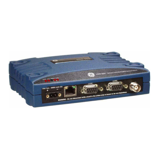
1.0 INTRODUCTION This manual is one of two publications for users of the MDS SD Series Transceiver shown in Figure 1. It contains an overview of common applications, installation planning data, specifica- tions, troubleshooting, and instructions for using the web-based Device Manager. This manual is intended for technical personnel who perform network design, configuration, and troubleshoot- ing of the equipment. -
Page 12: New Features In This Release
1.2 New Features in this Release The SD transceiver has been updated to include the following functionality in the latest release of the product: • Over-the-Air Compression to maximize bandwidth (See Page 44) • Internal Modbus TCP to RTU Conversion added for IP Payloads (see Page 56) •... -
Page 13: Product Description
2.0 PRODUCT DESCRIPTION The transceiver is a software-configurable, industrial radio for use in licensed data acquisition networks. It may be interfaced with a variety of data control equipment including remote termi- nal units (RTUs), programmable logic controllers (PLCs), flow computers, and similar devices. Data interface connections may be made for both serial (RS-232/RS-485) and Ethernet protocols. -
Page 14: Media Access Control (Mac)
• Terminal Server capability to enable IP addressing of serial interface ports on individual ra- dios • Store and Forward capability • Frequency Re-use that offers approximately 20 dB of additional co-channel isolation when operating networks on the same frequency. •... -
Page 15: Vlan Capability
VLAN Capability A Virtual Local Area Network (VLAN) is essentially a limited broadcast domain, meaning that all members of a VLAN receive broadcast frames sent by members of the same network, but not frames sent by members of a different network. The radio supports port-based VLAN at the Ethernet interface and over the air, in accordance with the IEEE 802.1Q standard. -
Page 16: Sd Model Offerings
To use this feature, a network must consist of all SDx radios. This feature is applicable only on digital modems (B modems are excluded). Note that this feature does not affect adjacent channel performance, but only co-channel performance. 2.3 SD Model Offerings The radio is offered in three model types, using one hardware platform: •... -
Page 17: Accessories And Spares
A retrofit kit is available for connector conversion (see Accessories & Spare Items). 2.5 Accessories and Spares Table 1 lists common accessories and spare items for the transceiver. GE MDS also offers an Accessories Selection Guide listing additional items that may be used with the product. Visit or contact your factory representative to obtain a copy of the guide. -
Page 18: Protected Network Station
Protected Network Station The transceiver is available in a protected network configuration, known as the SDxP (Figure 4), where x denotes the particular model of SD transceiver installed inside the chassis (i.e., SD1, 2, 4, 9, etc.). The SDxP is a tabletop or rack-mount unit designed to hold two transceivers, two power sup- plies, and a switchover logic board that automatically selects between transceiver A or B as the active unit. -
Page 19: Typical Applications
This section describes common scenarios the transceiver may be used in. A number of variations are possible; if you have unique requirements not found here, it is recommended that you consult a support specialist at GE MDS. Contact information is provided at the back of this manual. 3.1 Operating Parameters The transceiver can operate in both poll-response and “push”... -
Page 20: Example Systems
3.2 Example Systems The following sections describe common system arrangements for the transceiver. Other varia- tions are possible, and if you have questions about a specific application not covered here, you may contact your factory representative using the information at the back of this guide. For typi- cal radio settings in these systems, refer to Table 2 on Page 9. -
Page 21: Point-To-Point System
Point-to-Point System Where permitted, the transceiver may also be used in a point-to-point arrangement. A point-to- point system consists of just two radios — one Master and one Remote (see Figure 7). It pro- vides a simplex (or half-duplex) and a duplex communications link for the transfer of data be- tween two locations. -
Page 22: Port Sharing With Multiple Hosts
Figure 8. IP/Ethernet Polling Example The type of network shown in Figure 8 can also be used for general Ethernet bridging as sup- ported by the over-the-air bandwidth of the system. Bridge filters in the radio may be set to re- duce Ethernet traffic over the RF channel, and improve performance. -
Page 23: Push Communication (Report-By Exception)
eration for port sharing systems. See “Understanding the Use of Virtual Radio Channels (VRCs)” on Page 55. NOTE An option exists to operate in Packet mode without MAC. However, this Packet mode option should only be used for systems that use legacy methods of collision avoidance including Multihost and Listen Before Transmit (LBT). -
Page 24: Ip Polling Of Serial Remotes
DNP3 and IEC 104 are examples of protocols that implement push communication. Note that both the serial and Ethernet versions of DNP3 support push communication. IP Polling of Serial Remotes The transceiver is ideal for use in systems employing a mix of serial and Ethernet protocols. While many variations are possible, Figure 10 shows a typical arrangement with an Ethernet host at the Master Unit that is polling serial-based RTUs at Remote sites. - Page 25 By default, the radio’s port is configured for serial management functions with a connected COM1 PC, but it may be configured for data service using the web interface. This arrangement allows two telemetry networks to share a single radio system. Packet w/MAC is the recommended method of operation when both serial ports are used to pass payload data if there are two hosts (e.g., Port Sharing with multiple host case).
-
Page 26: Installation Planning
4.0 INSTALLATION PLANNING This section covers pre-installation factors that should be considered when installing the trans- ceiver in the field. Careful planning will help achieve optimal performance from the transceiver. After reviewing this section, refer to the step-by-step installation procedures beginning on Page Figure 12 shows a typical station arrangement. -
Page 27: Mounting Bracket Options
Figure 13. Transceiver Dimensions 4.2 Mounting Bracket Options The transceiver is normally provided with flat mounting brackets attached to the bottom of the radio as shown in Figure 14. An optional 35 mm DIN rail mounting bracket is also available, and is described below. -
Page 28: Antennas And Feedlines
A directional Yagi (Figure 16) or corner reflector antenna is generally used at remote sites to minimize interference to and from other users. Antennas of this type are available from several manufacturers, including GE MDS. Contact your factory representative for details. Figure 16. Typical Yagi Antenna (mounted to mast) Feed lines The selection of an antenna feed line is very important. -
Page 29: Dc Power Connection
The tables which follow show the approximate losses that will occur when using various lengths and types of coaxial cable in the 200, 400 and 900 MHz bands, respectively. Regardless of the type used, the cable should be kept as short as possible to minimize signal loss. Table 3. -
Page 30: Grounding Considerations
NOTE Early SD4 models supported 10.5 to 16 VDC power, not 10 to 30 VDC. Always check the labeling above the power connector to confirm the operating range for your unit. A power connector with screw terminals is provided with each unit (see Figure 17). Strip the wire leads to 6 mm (1/4 inch) and insert in the wire ports, tightening securely. -
Page 31: Serial Data Interfaces
NOTE Not all PCs have a serial port. If one is not available, a USB-to-Serial adapter and ap- propriate driver software may be used to provide serial connectivity. These adapters are available from several manufacturers, including GE MDS. COM1 (Serial) Connection The default factory settings for the radio’s... -
Page 32: Com2 (Data) Connections
wish to use serial or Telnet control, refer to the SD Serial/Telnet Management Supplement, Part No. 05-6193A01. Figure 19. COM1 Connector (DB-9F) As viewed from outside the unit For typical applications, a straight-through DB-9 cable may be used for PC management on . - Page 33 NOTE In addition to RS-485 mode, the radio is capable of operating in RS-422 mode. RS-485 must be selected in the menu, and the pin descriptions/wiring arrangements shown in Table 9 apply. Figure 21. COM2 Connector (DB-9F) As viewed from outside the radio NOTE The radio is hard-wired as a DCE device.
- Page 34 Table 9. COM2 Pin Descriptions — Radio in RS-485 Mode Radio Input/ Number Output Pin Description board. Alarm Output — Behavior is user-configurable. Default behavior: A high on this pin indicates an alarm condition; a low indicates normal operation. RXD+/RXB (Received Data +) — Non-inverting receiver input TXD+/TXB (Transmitted Data +) —...
-
Page 35: Step-By-Step Installation
5.0 STEP-BY-STEP INSTALLATION In most cases, the steps given here are sufficient to install the transceiver. Refer to “INSTALLATION PLANNING” on Page 16 for additional details, as required. 1. Mount the transceiver. Attach the mounting brackets to the bottom of the transceiver case (if not already installed), using the three 6-32 x 1/4 inch (6 mm) screws supplied. -
Page 36: Web-Based Management
Web-Based Management The Device Manager is the recommended method for user management. It is a built-in software tool that works with your PC’s browser to provide an intuitive, web-style presentation of all ra- dio information, settings, and diagnostics. The Device Manager also contains a “wizard” function to assist in setting up a radio with a min- imum of user actions. - Page 37 Figure 23. PC Connection to Radio for Web Management Logging On 1. Connect the radio to a PC via an Ethernet connection. 2. Configure your PC network settings to an IP address on the same subnet as the radio. The default subnet mask is 255.255.0.0 3.
- Page 38 pending on ordering options. If no frequencies have been set, an alarm condition is gen- erated and the LED flashes. These will be cleared after the frequencies are set. In all cases, users must verify that the frequencies are properly set according to the station license.
-
Page 39: Alternative Management Methods
Serial control, but may be performed either through a local connection, or over a net- work. For more information on alternative management methods, refer to the SD Serial/Telnet Man- agement Supplement, Part No. 05-6193A01, available from the GE MDS website at www.gemds.com 5.2 Initial Startup & Checkout In-service operation of the transceiver is completely automatic. -
Page 40: Ethernet Connector Leds
Table 10. LED Status Indicators LED Name Description These LEDs show data activity on the DB-9 serial payload DATA1 ports (COM1/COM2). DATA2 When lit, indicates that a communication link exists with LINK the Master Unit. Ethernet Connector LEDs The 10/100 Base-T Ethernet connector has two embedded LEDs. A flashing green indicator shows data activity, and a yellow indicates 100 Mbps operation has been achieved. -
Page 41: Ethernet Settings
NOTE Baud rate settings that are matched or higher than the modem speed should be used in all cases. If the baud rate must be lower than the modem speed, the Data Key Hold Time-out can be adjusted. See “ ”... -
Page 42: Using The Device Manager
6.0 USING THE DEVICE MANAGER The radio contains a built-in management system known as a Device Manager. This web-based tool is accessed with a PC connected to the radio’s Ethernet port as shown in Figure 26. It offers an intuitive method for managing your radio and performing common maintenance tasks. NOTE The Device Manager is the preferred method for managing the transceiver. -
Page 43: Overview Screen
Figure 27. Overview Summary Screen Overview Screen screen (Figure 27) provides a read-only view of all key settings and operating con- Overview ditions for the radio. The , in particular, can help you quickly spot Health & Maintenance Summary changes in operating conditions. By becoming familiar with expected readings, you can identify parameters that are outside their normal ranges, and take corrective action. -
Page 44: Management Tasks
Logging Out To exit the Device Manager, click in the upper right hand side of any screen. The session Logout is terminated. NOTE To maintain security, it is best to log-out of the Device Manager as soon as you are done working with it. - Page 45 Table 11. Device Manager Quick Reference Task Refer to this If you wish to... Category Screen/Section Set RF Output Power, Modem Type, RX/TX Configuration>>Radio, Frequency Basic Settings, Page 40 View/Set OTA Compression Configuration>>Radio, Packet Settings, Page 44 View/Set Soft-Carrier Dekey status, RX/TX Configuration>>...
- Page 46 Table 11. Device Manager Quick Reference Task Refer to this If you wish to... Category Screen/Section View Serial No., Model 1 (software), Model 2 Overview>> SD Summary, Page 33 (hardware) version, Firmware Version, Build Date Set Owner Name/Message, enable/disable Configuration>> Sleep Mode, set COM LED mode, Radio Mode Radio>>Device Settings, Page 43...
- Page 47 Table 11. Device Manager Quick Reference Task Refer to this If you wish to... Category Screen/Section Configuration>> Configure the IP settings (Static IP Address, Static IP Netmask, Static Default Gateway, Communication Ports>> DHCP enable/disable, Virtual Radio Channels– IP Configuration, Page 64 VRCs) Configure Ethernet Bridging, enable/disable Configuration>>...
- Page 48 Table 11. Device Manager Quick Reference Task Refer to this If you wish to... Category Screen/Section Maintenance & Status>> Start radio network reprogramming (and Firmware Utilities>> monitor progress) Remote Reprogramming, Page 78 Maintenance & Status>> Perform Ethernet PING to local Ethernet Radio Test>>Ping Test, host Page 75...
-
Page 49: Configuration Screens
NOTE The Device Manager screens shown in this manual were obtained from a radio operating in a lab environment and are provided as examples only. Not all content will be legible in these reduced size examples. Also, the parameters and settings shown may differ from those seen in field service conditions. -
Page 50: Radio
Radio Basic Settings screen contains important RF and modem selections for radio operation. Basic Settings • — The RF output power may be set between 20 and 37 dBm (0.1 to RF Output Power (dBm) 5 watts) in 1 dB increments. The default setting is . - Page 51 Table 12. Modem Selection vs. Speed, Bandwidth & Sensitivity Modem Type Over-the-air B/W (kHz) Approximate ETSI Selection Speed (bps) Sensitivity Compliance Modem 38400N 38400 25.0 -99 dBm Modem 65000 65000 50.0 -102 dBm Modem 65000N 65000 50.0 -94 dBm Modem 32000 32000 50.0 -104 dBm...
- Page 52 Figure 29. System ID Example — Valid Arrangement Figure 30. System ID Example — Invalid Arrangement (Will not operate properly with SD Transceivers) SD Series Technical Manual MDS 05-4846A01, Rev. I...
- Page 53 Device Settings • — An owner name and message may be entered for the radio Owner Name/Owner Message for informational purposes. These are “free-form” fields which do not affect the opera- tion of the radio in any way. Such fields might be used to identify the network adminis- trator/company name, and include a site-specific message (i.e., Unit 2 at North Tower site Up to 30 alpha-numeric characters may be entered (there is no minimum), and any print-...
- Page 54 • — This parameter selects the method of radio management for the Seri- User Interface al/Telnet interface. It has no effect on the web interface. The default selection is Menu Alternatively, you may select , which switches the radio to a Command Line Interface. With this interface, commands are entered in text-based fashion, as described in the SD Serial/Telnet Management Supplement, Part No.
-
Page 55: Media Access Control
Media Access Control (AP menu shown) • — Selects , or . An Access Point serves Device Type Access Point Remote Store and Forward as the Controller of the RF network. Only one radio is configured as an AP. Typically this is the “polling master.”... - Page 56 Figure 31 below depicts a typical single unit SAF network. This network supports a single SAF hop. Chained SAF hops are not allowed. However, multiple SAF radios are supported provided their RF coverage areas do not overlap, as this would create radio interference and severely re- duce throughput.
- Page 57 cal coverage area, keeping efficiency high. The transceiver achieves these steps automatically, and does not require user input. The following is an explanation of how this routing scheme is achieved. Initially, all Remote device routes are unknown. The Master/AP assumes that all undiscovered Remotes can potentially be on the SAF link.
- Page 58 • — This setting specifies the TCP port for DLINK communication. The ad- Dlink TCP Port dress for Ethernet-based DLINK communication is given by the radio's IP address (from screen) and the port number specified here. Overview Advanced Settings • —...
- Page 59 (i.e. 9790, 2100, x310) when running 9600B modem. Custom 2 allows SDx to communicate with 2710N units running 9600M modem. This value should al- ways be set to normal unless instructed to change it by GE MDS technical support for specific applications.
-
Page 60: Features
— Feature to enhance over-the-air data when using 38400N, Modem Transmit Tolerance 19200N and 4800F modems. This value should always be set to normal unless instructed to change it by GE MDS technical support for specific applications. Features Bridge Configuration •... - Page 61 • — When set as SMART, this filter prevents any packets which were transmitted Lan filter from one endpoint to another which are connected through a hub on a single transceiver. Default is AUTO NOTE This feature should be disabled if there is a redundant bridge in the network. VLAN Configuration A VLAN is essentially a limited broadcast domain, meaning that all members of a VLAN re- ceive broadcast frames sent by members of the same VLAN but not frames sent by members of a...
- Page 62 the data VLAN. This ID is used for filtering and tagging purposes. Any valid ID from may be entered. The Default Mgmt VLAN ID is 4095 • — Read only parameter (Reserved for Future use) Access Mode Tag • — Defines the native VLAN interface as .
- Page 63 • — These settings refer to the time period (in milliseconds) to Min/Max Channel Wait (ms) wait after the channel is free before transmission is allowed. Minimum wait time: Normally, the minimum channel wait time should not be changed from its default setting of unless performing advanced operations, such as staggering 0 ms the responses from multiple Remotes.
- Page 64 The radio supports Ethernet operation on three IP payload ports. These settings are made on the as shown in the screen which follows later in this section. IP Payload Configuration (1, 2, or 3) Menu In the Master unit only, Multihost may need to be enabled if more than one IP Payload port is required.
-
Page 65: Understanding The Use Of Virtual Radio Channels (Vrcs)
• — Used to specify a port number for the RJ-45 modular connector on Local Radio IP Port the radio’s front panel. As a general rule, port numbers below 2000 should be avoided, as some are reserved for special applications in data networks. •... - Page 66 Any combination of the three VRC numbers may be entered in the selection fields. Figure 32 illustrates the relationship between the VRC settings and the routing of data between units. Figure 32. Virtual Radio Channel (VRC) Concept Terminal Server COM1/2 Configuration The radio’s Terminal Server feature allows IP addressing of the COM1 and COM2 serial inter- face ports.
-
Page 67: Using The Terminal Server - Typical Example
NOTE Available selections vary depending on the mode selected. • — Enables or disables the Terminal Server feature. Status • — Sets the operating mode for the IP port. It may be set to Mode UDP Socket TCP Client , or to match the service in which it will Socket TCP Server Socket... - Page 68 Figure 33. Terminal Server Example IP/Radio Network Setup and Configuration The following conditions are assumed for this example: • Radio (RF) link is good between AP and Remote 1, and AP and Remote 2. • IP addresses are properly configured as shown in Figure 33. •...
- Page 69 Baud Rate: 115200 bps Format: 8 char bits, no parity, 1 stop bit Buffer: Data Handling ON Device: DCE Talk on: VRC-1 Listen to: ALL 3. Click after the changes are made. Commit Configuration To test the functionality of the Terminal Server, open a HyperTerminal session on PC1 and con- nect to the Remote 1 Terminal Server as shown in Figure 34.
- Page 70 Figure 36. Remote 2 Terminal Server Connection On PC3, open a HyperTerminal session and connect to Remote 2’s COM2 port as shown in Fig- ure 37. Figure 37. Remote 2 COM2 Port Connection Type “hello” in the Remote 1 Terminal Server window. Note delivery of the message only to the Remote 1 COM2 Port window (see Figure 38).
- Page 71 Figure 38. Remote 1 Terminal Server/COM2 Port Communication Type “how are you” in the Remote 2 terminal server window (see Figure 39). Note delivery of the message only to the Remote 2 COM2 Port window. Type “good” in the Remote 2 COM2 Port window.
-
Page 72: Communications Ports
• — Enables or disables multihost capability. Multihost Enable • — Sets the desired delay time (in ms) for switching between hosts during Multihost Delay multihost operation. Peer-to-Peer (Peer2Peer) • — Determines if the AP will allow enabled Peers to com- Rebroadcast Allowed (AP only) municate through the AP to other enabled Peers (serial data only). - Page 73 • — The mode setting for the port may be changed on demand ( Current Mode COM1 Console ) using this selection. Data • — The default data rate for , but it may be set to any of Data Baud Rate COM1 115200 bps the following speeds: 300, 600, 1200, 2400, 4800, 9600, 19200, 38400, 57600, 115200.
- Page 74 8 character bits, even parity, 2 stop bits 7 character bits, no parity, 1 stop bit 7 character bits, no parity, 2 stop bits 7 character bits, odd parity, 1 stop bit 7 character bits, odd parity, 2 stop bits 7 character bits, even parity, 1 stop bit 7 character bits, even parity, 2 stop bits •...
- Page 75 • — Read-only indication of the current default gateway pro- Current Default Gateway grammed. • — The radio requires a local IP address to support remote management Static IP Address and serial device (terminal server) services. An IPv4 IP address should be entered in this field, unless DHCP is enabled, in which case it is not required.
-
Page 76: Security
ing new devices on the network with minimal manual intervention. The assigned parame- ters are valid for a specific “lease” time, at which point they can be reassigned or re- newed. Security The transceiver offers a number of safeguards against unauthorized management access and pro- tection of payload data. - Page 77 NOTE If web access has been disabled accidently via the web Device Manager, the user must re-enabled it via the console or Telnet interface. Wireless Security • — When on, applies encryption to payload data stream. The default se- Payload Encryption lection is Login Password •...
-
Page 78: Maintenance & Status Screens
NOTE If the radio login password is lost or forgotten, contact GE MDS for assistance. Proof of authorized user is required for a new password, and the radio will revert to its default settings. It is recommended that users periodically export their configuration file so that it can be loaded back into the radio if their old one requires replacement. -
Page 79: Event Log
Figure 40. Maintenance & Status Screen Event Log The Event Log is used to display all events stored by the transceiver, even if the radio has been power-cycled. It also shows a running total of the alarms stored. • — Displays the number of events that have been logged by the Total Event Log Events transceiver. - Page 80 This menu is read only. Status Conditions and Events This screen shows status conditions reported since power-up of the transceiver. This includes normal, informational events such as booting up the system and re-initializing. This menu is read only. Alarm Signal Configuration This screen contains settings to determine what events are detected, and what will be done with them.
-
Page 81: Performance
• — This parameter may be set to either . An ac- Alarm Signal Sense Active High Active Low tive high means that Pin 6 on the port will output a high DC signal when an alarm COM2 exists. (This is the default behavior.) An active low means that Pin 6 on the port COM2 will output a low DC signal when an alarm exists. - Page 82 • — Read-only indication of the measured RF output power (in dBm). Measured RF Power • — Read-only indication of the signal-to-noise ratio of received signal. Signal to Noise • —Displays the signal to noise and distortion ratio of the analog signal - Read only SINAD when not in x710/Analog mode.
- Page 83 • — Clicking this button resets the displayed statistic counts. Clear Statistics MAC Routes function pertains to Packet w/MAC operation and it is used as a networking tool. MAC Routes It works on both APs and Remotes, but is generally most meaningful from an AP perspective. screen shows all currently communicating radios in a network running in Packet MAC Routes w/MAC mode.
- Page 84 Note that because the radio network is point-to-multipoint (from a Remote radio's perspective), function only contains information about the Access Point. MAC Route Radio Test The Radio Test functions are a collection of tools useful for testing the RF performance of the transceiver.
- Page 85 • — Enter the number of times for the message to be sent across the radio Linktest Count link. • — Enter the time (in milliseconds) that will result in a timeout if Response Timeouts (msec) no response is received within that period. •...
- Page 86 To use the Spectrum Graph, you must first specify a center frequency and a span frequency. The center frequency is the frequency that you wish the spectrum display to be centered on. The span frequency defines the width of the overall spectrum to be examined. •...
-
Page 87: Firmware Utilities
Firmware Utilities Version Information This screen shows Bootloader version information and indicates which firmware image (1 or 2) is currently active, as well as the firmware version of each image. The information on this screen is read-only. This section is read only. NOTE The latest firmware version for this product can be obtained at www.gemds.com. - Page 88 TFTP Reprogramming screen contains settable parameters for TFTP file transfers and selec- TFTP Reprogramming tions for retrieving files, such as radio firmware or configuration files. • — Use this field to enter a valid IP address for the host computer (where file to be Host IP transferred resides).
- Page 89 • — Set to either intrusive or passive as desired. Channel Usage • — Used to specify the size of the reprogramming data packets. Default Packet Data Size size is • — Used to specify the number of times a transmission is repeated when a Retry Count packet is not received correctly.
- Page 90 Copy Image • — Shows the firmware package currently being used by the transceiver (1 or Active Image • — Shows the version of firmware package 1. Package 1 • — Shows the version of firmware package 2. Package 2 •...
-
Page 91: Configuration Files
• — A factory furnished code used to enable operating features of the Authorization Key transceiver. An error message is returned if an invalid authorization key is entered. Con- tact your factory representative for ordering details. Configuration Files NOTE It is recommended that users periodically export their configuration file so that it can be loaded back into the radio if their old one requires replacement. - Page 92 • — Enter a valid IP address here for the host computer (where the configu- Host IP Address ration file resides or where you want to send it). • — Enter the exact name of the configuration text file that will be used by the ra- Filename dio to import or export configuration data.
-
Page 93: Troubleshooting
7.0 TROUBLESHOOTING Successful troubleshooting of the radio system requires a logical approach. It is best to begin troubleshooting at the Master unit, as the rest of the system depends on the Master for polling commands. If the Master unit has problems, the overall operation of the network will be affected. It is good practice to start by checking the simple things. -
Page 94: Led Indicators
Correct as necessary. c. Re-enable Sleep Mode on Device Settings Screen, re- connect device to COM2, and check for proper operation. Password lost or Contact GE MDS for password reset authorization code. Proof of forgotten authorized user required. Alarm message No load on Antenna connector or poor/shorted/open load. -
Page 95: Checking For Alarms/Events
Table 15 contains a listing of event codes that may be reported by the transceiver. The codes shown are a subset of a larger pool of codes used for various GE MDS products. For this reason, the table does not show a sequential listing of all code numbers. Only the codes applicable to this product series are shown. - Page 96 Table 15. Event Codes Event Code Event Class Description Not currently implemented. Major Not currently implemented. Major Frequency not programmed. Major Authorization fault detected. Major RF synthesizer out-of-lock condition. Major Not currently implemented. Major Not currently implemented. Major Not currently implemented. Major Radio not calibrated.
-
Page 97: Operating Constraints
Table 15. Event Codes Event Code Event Class Description tolerance, operation may fail. Not currently implemented. Minor Not currently implemented. Minor RF Output Power not in valid range. Minor Not currently implemented. Minor Internal temperature approaching limit. Minor Booting up. Inform System initialization complete. - Page 98 Table 16. Operating Constraints Constraint Detailed Information RSSI display in strong The RSSI facility limits the maximum displayed signal signal environments strength to –60 dBm. Signal levels that are higher than -60 dBm will appear as > -60 dBm. Radio operation in strong Operation with very strong receive signals (>...
-
Page 99: Technical Reference
Diagnostics data from a remote radio can be obtained by connecting a laptop or personal com- puter running GE MDS diagnostic software, such as MDS PulseNET or MDS InSite to any radio in the network. InSite is designed for operation with a serial-based (COM1) connection, unless using a terminal server. -
Page 100: Setting Up Diagnostics
NOTE This section of the manual focuses on the use of the radio’s Ethernet port for diagnostic configuration (i.e., PulseNET-based diagnostics, or InSite with a terminal server). Alter- natively, the COM1 port may be used for serial diagnostics. See the SD Serial/Telnet Management Supplement, Part No. - Page 101 operation means that the payload application data will be interrupted while program- Intrusive ming data is sent over the air. This is the fastest method of programming radios over the air, but it comes at the cost of interruptions in the primary use of the radio network. See Table 17 for the approximate times needed for intrusive reprogramming.
-
Page 102: Broadcast Reprogramming Suggestions By Network Type
NOTE It is possible for Remote radios receiving a firmware upgrade to complete reprogram- ming before the initiating station does. This is because transmissions are sent out “broadcast style” and will be sent up to the number of times entered in the Retry Count parameter of the radio. -
Page 103: Cancelling Ota Reprogramming
ceiving stations. This last option instructs the receivers to reboot to a specific firmware revision if available, and not already running at that revision. Cancelling OTA Reprogramming During the reprogramming operation the user has the ability to cancel reprogramming at any time either on the initiator, which will affect all radios, or on individual receiving stations. -
Page 104: Com1 Operating Modes
Data mode or Management mode, where user input can be accepted via either a menu interface, a command line interface, or a diagnostic interface such as GE MDS- proprietary DLINK protocol. The list below shows all possible modes for the... -
Page 105: Implementing Sleep Mode
NOTE The COM1 operating mode may also be set using a PC terminal connected directly to the port. See SD Serial/Telnet Management Supplement, Part No. 05-6193A01 for de- tails. 8.4 Implementing Sleep Mode Sleep Mode places the transceiver into a low power “hibernating” state, with a nominal current draw of less than 12 mA (at 13 VDC) and a “wake-up”... -
Page 106: Technical Specifications
SD9: 5.0, 12.5, 25.0, 50.0 kHz NOTE: This information subject to change depending on specific modem configuration. For emission designator information, consult the FCC website for latest “GE MDS” grants: http://transition.fcc.gov/oet/ea/fccid/. Emission designators are subject to change pending new FCC additions and approvals. - Page 107 SD4: E5MDS-SD4 SD9: E5MDS-SD9-1 IC ID SD1: 101D-SD1 SD2: 101D-SD2-1 SD4: 101D-SD4 SD9: 101D-SD9-1 DATA CHARACTERISTICS Signaling Types RS-232/485; DB-9 Female connector Ethernet 10/100 Mbps; RJ-45F connector COM2 Data Rates 300–115200 bps, asynchronous Data Latency 11 ms typical (transparent) PRIMARY POWER Voltage 10.0 to 30 VDC (Negative ground only) NOTE: Early SD4 models supported 10.5 to 16 VDC power, not 10 to 30 VDC.
-
Page 108: Dbm-Watts-Volts Conversion Chart
8.6 dBm-Watts-Volts Conversion Chart Table 20 is provided as a convenience for determining the equivalent wattage or voltage of an RF power expressed in dBm. Table 20. dBm-Watts-Volts Conversion — for 50 Ohm Systems µV 100.0 200W .225 1.0mW 0.80 70.7 100W .200... -
Page 109: Glossary Of Terms & Abbreviations
The transceiver described in this manual is hardwired as a DCE device. Digital Signal Processing — See DSP. DLINK — Data Link Mode. This is a GE MDS-proprietary protocol used when the transceiver is in diagnostics mode. MDS 05-4864A01, Rev. I... - Page 110 DSP — Digital Signal Processing. The transceiver’s DSP is the core operating unit of the trans- ceiver through which nearly all functions depend. DTE — Data Terminal Equipment. A device that provides data in the form of digital signals at its output.
- Page 111 Multiple Address System — See MAS. Network-Wide Diagnostics — An advanced method of controlling and interrogating GE MDS radios in a radio network. Node — An operating mode of the transceiver with respect to diagnostic/management activities.
- Page 112 VLAN — Virtual Local Area Network WAN — Wide Area Network x710 — The generic name for GE MDS legacy transceiver-family products, including the MDS 9710 (900 MHz), MDS 4710 (400 MHz), 2710 (200 MHz) and MDS 1710 (100 MHz).
- Page 113 NOTES MDS 05-4864A01, Rev. I SD Series Technical Manual...
- Page 114 SD Series Technical Manual MDS 05-4846A01, Rev. I...
- Page 115 IN CASE OF DIFFICULTY... GE MDS products are designed for long life and trouble-free operation. However, this equip- ment, as with all electronic equipment, may have an occasional component failure. The follow- ing information will assist you in the event that servicing becomes necessary.