
Related Manuals for GE MDS iNET Series


Summary of Contents for GE MDS iNET Series
- Page 1 MDS iNET Series MDS iNET-II 900 MDS iNET 900 Wireless IP/Ethernet Transceiver iNET-II 900 and iNET 900 Firmware Release 8.1.1 and later MDS 05-2806A01, Rev. L OCTOBER 2014...
- Page 2 Quick-Start instructions for this product are contained in publication 05-2873A01. Visit our web site for downloadable copies of all documentation at www.gemds.com.
-
Page 3: Table Of Contents
1.4.3 Collocating Multiple Radio Networks ................. 10 The Network Name and the association process ..............10 Can radio frequency interference (RFI) disrupt my wireless network? ........10 1.5 Cyber Security .......................11 1.6 Accessories........................12 05-2806A01, Rev. L MDS iNET Series Reference Manual... - Page 4 2.5.1 Radio Configuration Menu ....................40 2.5.2 Channel Config Menu ......................42 2.5.3 Advanced Configuration Menu ..................44 2.5.4 Skip Zones Menu ......................44 2.5.5 Auto Data Rate Configuration Menu .................. 45 MDS iNET Series Reference Manual 05-2806A01, Rev. L...
- Page 5 2.8.1 RSSI by Zone Menu (Remotes Only) ................71 2.8.2 Event Log Menu ........................ 71 Time and Date......................... 72 View Current Alarms ....................... 73 View Event Log ........................73 2.8.3 Packet Statistics Menu ...................... 74 05-2806A01, Rev. L MDS iNET Series Reference Manual...
- Page 6 3.3.2 Packet Statistics Menu ...................... 98 3.3.3 Serial Port Statistics Menu ....................98 3.3.4 Diagnostic Tools ........................ 98 3.4 Using Logged Operation Events ................... 99 3.5 Alarm/Event Conditions ....................99 3.6 Correcting Alarm Conditions ..................100 MDS iNET Series Reference Manual 05-2806A01, Rev. L...
- Page 7 4.4.8 Maximizing Throughput ....................119 4.4.9 Placing an iNET Radio Behind a Firewall ................ 120 4.5 SNMPv3 Notes ......................120 4.5.1 Overview ......................... 120 SNMPv3 Accounts ........................ 120 Context Names ........................121 Password-Mode Management Changes................121 05-2806A01, Rev. L MDS iNET Series Reference Manual...
- Page 8 & Abbreviations............148 Copyright and Publication Notices This publication is protected under copyright law. Copyright 2014, GE MDS. All rights reserved. Historical revision note: There was no “Rev. I” issued for this manual, to avoid confusion with the digit “1.” Publication went from Rev. H directly to Rev. K.
- Page 9 We also became experts in wireless communication standards and system applications worldwide. The result of our efforts is that today, thousands of utilities around the world rely on GE MDS-based wireless networks to manage their critical assets.
- Page 10 Part 15 rules also require that the Effective Isotropic Radiated Power (EIRP) from an GE MDS iNET Series installation not exceed 36 dBm. Refer to Antenna &...
- Page 11 These systems will reuse or recycle most of the materials found in this equipment in a sound way. Please contact GE MDS or your supplier for more information on the proper disposal of this equipment.
- Page 12 MDS iNET Series Reference Manual 05-2806A01, Rev. L...
-
Page 13: Product Overview And Applications
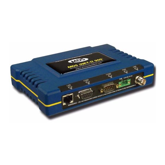
1.2 Product Description The GE MDS iNET 900 transceiver (Figure 1-1) provides an easy-to-install wireless local area network (WLAN) service with long range and secure operation. It supports both Ethernet and serial data interface options at over-the-air data speeds of up to 1 Mbps (iNET-II) and 512 kbps (iNET). -
Page 14: Secure Operation
Secure Operation Data network security is a vital issue in today's wireless world. MDS iNET Series radios provide multiple tools to help you build a network that minimizes the risk of eavesdropping and unauthorized access. Some are inherent in the radio’s operation, such as the use of 900 MHz spread-spectrum transmissions; others include data encryption, enabling/disabling remote access channels, and password protection. -
Page 15: Model Offerings
The MDS iNET and MDS iNET-II transceivers are not over-the-air compatible. NOTE: The radio does not support the simultaneous use of Fragmentation and Encryption. If encryption is enabled (other than RADIUS), the fragmentation option will not be available. 05-2806A01, Rev. L MDS iNET Series Reference Manual... -
Page 16: Mds P21 Protected Network (Redundant) Configuration
1.2.4 MDS P21 Protected Network (Redundant) Configuration For mission-critical applications, GE MDS also offers the Protected Network Station. This radio incorpo- rates two iNET Series transceivers, two power supplies, and a switchover logic board that automatically selects between Transceiver A and Transceiver B as the active radio. Figure 1-2 shows a view of the pro- tected chassis. -
Page 17: Point-To-Point Lan Extension
TransNET and others. In the case of radios using a single port for data and diagnostics, the capabilities are doubled. The data streams are delivered to an IP socket in an application, or in serial format using the Access Point. See Figure 1-5 on Page 6. 05-2806A01, Rev. L MDS iNET Series Reference Manual... -
Page 18: Multiple Protocols And/Or Services
Other cost reductions come from the system as a whole, such as reduced management requirements. And above all, the radio offers potential for future applications that run over Ethernet and IP, such as video for remote surveillance. MDS iNET Series Reference Manual 05-2806A01, Rev. L... -
Page 19: Wireless Lan With Mixed Services
Millions of wireless data products have been sold in the last two decades for licensed and license-free oper- ation, many of them manufactured by GE MDS. There are several ways that these systems can benefit from incorporating iNET equipment. The chief advantages are interface flexibility (serial and Ethernet in one unit), and higher data throughput. -
Page 20: Supplement Legacy Wireless Networks With Ip Services
Invisible place holder Remote REPEATER Access Point Ethernet Remote Remote Crossover Cable Access Point Remote LAN/WAN Figure 1-8. Typical LAN with a Repeater Link MDS iNET Series Reference Manual 05-2806A01, Rev. L... -
Page 21: Option 2-Using The Ap As A Store-And-Forward Packet Repeater
1.4.2 Protected Network Operation using Multiple Access Points Although GE MDS transceivers have a very robust design and have undergone intensive testing before being shipped, it is possible for isolated failures to occur. In mission-critical applications, down time can be virtually eliminated by using some, or all, of the following configurations: 05-2806A01, Rev. -
Page 22: Collocating Multiple Radio Networks
AP antennas on the same support structure. If that does not work, con- sult with your factory representative about other techniques for controlling radio frequency interference between the radios. (See “A Word About Radio Interference” on Page 112 for more details.) MDS iNET Series Reference Manual 05-2806A01, Rev. L... -
Page 23: Cyber Security
• Proprietary data framing Eavesdropping, intercepting messages • AES-128 encryption (iNET-II) • RC4-128 encryption (iNET) Key cracking software • Automatic Rotating Key algorithm Replaying messages • Automatic Rotating Key algorithm 05-2806A01, Rev. L MDS iNET Series Reference Manual... -
Page 24: Accessories
1.6 Accessories Table 1-4 lists common accessories and spare items for the transceiver. GE MDS also offers an Accessories Selection Guide listing an array of additional items that may be used with the product. Contact your factory representative or visit to obtain a copy of the guide. - Page 25 For more information, go to www.gedigitalenergy.com/Communications/ pulsenet.htm. Bandpass Filter Antenna system filter that helps eliminate 20-2822A02 interference from nearby paging transmitters. Ethernet Surge Surge suppressor for protection of Ethernet port 29-4018A01 Suppressor against lightning. 05-2806A01, Rev. L MDS iNET Series Reference Manual...
-
Page 26: Embedded Management System
For support of other SNMP software, a set of MIB files is available for download from the GE MDS Web site at www.gedigitalenergy.com/Communications. A brief sum- mary of SNMP commands can be found at section 2.4.5 on page 36 of this manual. - Page 27 Figure 2-1. Embedded Management System—Top-level Flowchart 05-2806A01, Rev. L MDS iNET Series Reference Manual...
-
Page 28: Differences In The User Interfaces
Figure 2-2. View of MS with a text-based program— (Terminal Emulator shown—Telnet has similar menu structure) Invisible place holder Figure 2-3. View of the MS with a Browser (Selections at left provide links to the various menus) MDS iNET Series Reference Manual 05-2806A01, Rev. L... -
Page 29: Accessing The Menu System
Starting a Local Console Session (Recommended for first-time log-in) 1. Connect a serial communications cable between the PC and the unit’s COM 1 port. If necessary, a cable may be constructed for this purpose as shown in Figure 2-5. 05-2806A01, Rev. L MDS iNET Series Reference Manual... - Page 30 Passwords are case sensitive. Do not use punctuation mark characters. You may use up to eight alpha-numeric characters. The unit responds with the Starting Information Screen (Figure 2-6). From here, you can review basic infor- mation about the unit or press to proceed to the Main Menu. MDS iNET Series Reference Manual 05-2806A01, Rev. L...
-
Page 31: Starting A Telnet Session
, in accordance with radio model). iNET iNET-II Press ENTER Next, the prompt appears. Enter your password (default password is ). (For security, Password: admin your password keystrokes will not appear on the screen.) Press ENTER 05-2806A01, Rev. L MDS iNET Series Reference Manual... -
Page 32: Starting A Web Browser Session
. The unit responds with a startup menu screen similar to that shown in Figure 2-8. From here, you can review basic information about the unit or click on one of the menu items at the left side of the screen. MDS iNET Series Reference Manual 05-2806A01, Rev. L... -
Page 33: Navigating The Menus
ESCAPE cancel the action and restore the previous values. Logging Out Via Terminal Emulator or Telnet From the Main Menu screen, press to quit and terminate the session. 05-2806A01, Rev. L MDS iNET Series Reference Manual... -
Page 34: Navigating Via Web Browser
Do not use a colon (:) or percent (%) symbol in the device name. • —The name of the radio network in which the unit is associated [ Network Name 9 to 15 characters Not Programmed MDS iNET Series Reference Manual 05-2806A01, Rev. L... - Page 35 —High-level view of configured system parameters. This shows parameters Configuration Summary that are currently enabled or being used. View Figure 2-10 below and Figure 2-11 on Page 24 for details. Figure 2-10. Configuration Summary Screen (iNET-II AP) 05-2806A01, Rev. L MDS iNET Series Reference Manual...
-
Page 36: Main Menu
The next screen, the Main Menu, is the entryway to all user-controllable features. The transceiver’s Device appears at the top of this and all other screens as a reminder of the unit that is currently being con- Name trolled Figure 2-12. Main Menu MDS iNET Series Reference Manual 05-2806A01, Rev. L... -
Page 37: Configuring Basic Device Parameters
(Display only) • —Used to set/display data communications rate (in bits-per-second) between a Console Baud Rate connected console terminal and the radio. [ 1200, 2400, 4800, 9600, 19200, 38400, 57600, 115200; 19200 05-2806A01, Rev. L MDS iNET Series Reference Manual... -
Page 38: Device Names Menu
—User defined; appears on this screen only. Owner • —User defined; appears on this screen only. Contact • —User defined; appears on this screen only. Description • —User defined; appears on this screen only. Location MDS iNET Series Reference Manual 05-2806A01, Rev. L... -
Page 39: Login Status Menu
This Menu contains parameters related to the operation of TCP/IP and Ethernet protocols. There are some differences between AP and Remote type radios regarding these parameters and they are noted where appro- priate. Invisible place holder Figure 2-16. Network Configuration Menu From Access Point 05-2806A01, Rev. L MDS iNET Series Reference Manual... - Page 40 —Presents a menu for configuring the Virtual LAN (VLAN) and IP address Interface Configuration of the transceiver. Detailed explanations are provided in the section titled “Network Interface Con- figuration Menu” on Page 29. MDS iNET Series Reference Manual 05-2806A01, Rev. L...
-
Page 41: Network Interface Configuration Menu
—Allows configuration of IP Addressing parameters. See “Configuring the IP Address Configuration IP Address when VLAN Status is Enabled” on Page 31, or “Configuring the IP Address When VLAN Status is Disabled” on Page 32. 05-2806A01, Rev. L MDS iNET Series Reference Manual... -
Page 42: Virtual Lan In Inet Series
NOTE: A change made to the above parameter will result in the Commit Changes option appearing on screen. This will modify the appearance of the screen depending on the option selected. MDS iNET Series Reference Manual 05-2806A01, Rev. L... -
Page 43: Configuring The Ip Address When Vlan Status Is Enabled
Selecting option H from Figure 2-19 shows Figure 2-21. Note that the IP address is different although it is the same physical unit. This is because this IP address is defined for a different VLAN. 05-2806A01, Rev. L MDS iNET Series Reference Manual... -
Page 44: Configuring The Ip Address When Vlan Status Is Disabled
When dynamic addressing is used, the radio uses a DHCP Client process to obtain an IP address from a DHCP Server, along with other parameters such as a subnet mask and a default gateway. Invisible place holder Figure 2-22. IP Address Configuration Menu MDS iNET Series Reference Manual 05-2806A01, Rev. L... -
Page 45: Ethernet Port Configuration Menu
Confirm that your hub/switch is capable of auto-switching data rates. To prevent Ethernet traffic from degrading performance, place the transceiver in a segment, or behind routers. Figure 2-23. Ethernet Port Configuration Menu (AP menu shown; Remote omits items D through G) 05-2806A01, Rev. L MDS iNET Series Reference Manual... - Page 46 IP addresses responds. Using the AND logic, if one or both of the IP addresses are no longer reachable, the beacon signal will change to “NOT AVAILABLE” until the connectivity returns. [OR; AND, OR] MDS iNET Series Reference Manual 05-2806A01, Rev. L...
-
Page 47: Dhcp Server Configuration
0.0.0.0 • —Domain Name Server address to be provided by this service. [ DNS Address 0.0.0.0 • —Windows Internet Naming Service server address to be provided by this service. WINS Address 0.0.0.0 05-2806A01, Rev. L MDS iNET Series Reference Manual... -
Page 48: Snmp Agent Configuration
This allows the flexibility to change areas of the MIB and not affect other existing installations or cus- tomers. • —GE MDS sub-tree registrations msdreg.mib • —GE MDS Common MIB definitions for objects and events common to the entire mds_comm.mib product family • —GE MDS sub-tree registrations inet_reg.mib •... -
Page 49: Trap Manager Submenu
2.4.6 Trap Manager Submenu Invisible place holder Figure 2-27. SNMP Trap Manager Configuration Menu —Configure up to five locations on the network to which traps are sent Trap Manager #1-5 [Any standard IP address; 0.0.0.0] 05-2806A01, Rev. L MDS iNET Series Reference Manual... -
Page 50: Snmp V3 Accounts Submenu
AP. This event happens only when the current AP is not the first entry in the Approved AP List, which means that the remote is not connected to the primary AP. MDS iNET Series Reference Manual 05-2806A01, Rev. L... -
Page 51: Bridge Configuration Submenu
Bridge Protocol Data Unit (BPDU) Time between transmissions of Hello mes- sages, in seconds. [1-10 seconds; 5seconds] • —View/set spanning tree forwarding delay. Affects how long the bridge Bridge Forwarding Delay spends listening and learning after initialization. [1-30 seconds; 5 seconds] 05-2806A01, Rev. L MDS iNET Series Reference Manual... -
Page 52: Radio Configuration
RF Output Power local regulatory limitations and losses in antenna transmission line. (See “How Much Output Power Can be Used?” on Page 112 for information on how to calculate this value.) 20–30; 20 MDS iNET Series Reference Manual 05-2806A01, Rev. L... - Page 53 —Number of bytes for the over-the-air RTS/CTS handshake boundary. (See “Perfor- RTS Threshold mance Notes” on Page 117.) [ 0 to 1600 bytes; 500 NOTE: While the transceiver accepts RTS Threshold settings below 100, the lowest functioning value is 100. 05-2806A01, Rev. L MDS iNET Series Reference Manual...
-
Page 54: Channel Config Menu
The radio hops only on the channels selected in this menu. NOTE: This menu changes when Beacon Learning is changed from . This applies to enabled on assoc iNET-II radios only. See Figure 2-34 on Page MDS iNET Series Reference Manual 05-2806A01, Rev. L... - Page 55 The options above are only configurable on the AP radio unless Beacon Learning on the Remote is set for . Remotes display this information as it is read from the AP. onassoc disabled 05-2806A01, Rev. L MDS iNET Series Reference Manual...
-
Page 56: Advanced Configuration Menu
Mobility is enabled. NOTE: These features should remain untouched unless instructed by GE MDS personal. Figure 2-35. Advanced Configuration Submenu • —Action to take when the FPGA reset period expires. -
Page 57: Auto Data Rate Configuration Menu
The Auto Data Rate Configuration submenu is typically for use in environments where signal quality is vari- able, and you wish to maintain the highest possible over-the-air data rate as conditions change. 05-2806A01, Rev. L MDS iNET Series Reference Manual... - Page 58 -50 dBm and -90 dBm provide reliable operation, provided the signal-to-noise ratio is 17 dB or above. Tailoring the thresholds with these baseline values in mind, can provide improved performance in your system. MDS iNET Series Reference Manual 05-2806A01, Rev. L...
-
Page 59: Mobility Configuration Menu
An Access Point is removed from the blacklist table when it has been in the table longer than the time set by the Blacklist Timer When mobility is enabled and beacon learning is on association, the dropped AP’s channels are excluded from scanning during the blacklist time. 05-2806A01, Rev. L MDS iNET Series Reference Manual... -
Page 60: Additional Considerations For Mobile Operation
• Use middleware—The use of middleware in the mobile laptops is highly recommended for better oper- ation of a mobile data system. GE MDS provides middleware from one of the vendors in this market. Contact your factory representative for details. -
Page 61: Configuring The Serial Ports
TCP server. Alternately, TCP clients actively attempt to estab- lish a connection with a TCP server. In the case of the transceiver, this happens whenever data is received on the serial port. 05-2806A01, Rev. L MDS iNET Series Reference Manual... -
Page 62: Udp Multicast
MODBUS/TCP is only supported on MDS iNET 900 ENI and MDS iNET-II 900 radios. Refer to your product to determine the radio’s capabilities. The transceiver implements a MODBUS/TCP server that bridges MODBUS/TCP to either Modbus RTU . It does not function as a MODBUS/TCP client. Modbus/ASCII MDS iNET Series Reference Manual 05-2806A01, Rev. L... -
Page 63: Data Buffering
2.6.2 Serial Data Port Configuration Menu The first two menu items present the identical parameter fields for each port with one exception—Flow Control. This is available only on COM2. 05-2806A01, Rev. L MDS iNET Series Reference Manual... -
Page 64: Configuring For Udp Mode
Local IP Address Must be configured with a valid Class D IP address (224.0.0.0–239.255.255.255). IP packets received with a matching destination address will be processed by this unit [ Any valid IP address; 0.0.0.0 MDS iNET Series Reference Manual 05-2806A01, Rev. L... - Page 65 —Save and execute changes made on this screen (Shown only Commit Changes and Exit Wizard after changes have been entered.) Invisible place holder Figure 2-41. UDP Point-to-Point Menu Use UDP point-to-point configuration to send information to a single device. 05-2806A01, Rev. L MDS iNET Series Reference Manual...
-
Page 66: Configuring For Tcp Mode
—Save and execute changes made on this screen (Shown only Commit Changes and Exit Wizard after changes have been entered.) 2.6.4 Configuring for TCP Mode Invisible place holder Figure 2-42. TCP Client Menu (Remote) • —Enable/Disable the serial data port. Status MDS iNET Series Reference Manual 05-2806A01, Rev. L... - Page 67 —Enable/Disable the serial data port. Status • —TCP Server. This is the type of IP port that will be offered by the transceiver’s IP Protocol serial device server. [TCP, UDP, PPP, DF1/EIP, MODBUS/TCP Server; TCP] 05-2806A01, Rev. L MDS iNET Series Reference Manual...
-
Page 68: Configuring For Ppp Mode
Byte Format 7N1, 7E1, 701, 7N2, 7E2, 702, 8N1, 8E1, 801, 8N2, 8E2, 802; 8N1 • (COM2 only)—RTS/CTS handshaking between the transceiver and the connected Flow Control device. [ Enabled, Disabled; Disabled MDS iNET Series Reference Manual 05-2806A01, Rev. L... -
Page 69: Configuring For Df1/Eip
—Text to identify the sender. Email From String [Valid email address; blank] • —The desired IP addresses for message routing. IP Routing Information • —The desired email destination address(es) for message routing. Email Routing Information 05-2806A01, Rev. L MDS iNET Series Reference Manual... -
Page 70: Configuring For Modbus/Tcp Server
The TCP session has a timeout of 10 minutes (600 seconds). If inactive for that time, it will be closed. The transceiver will offer the port again for connection after this time expires. MDS iNET Series Reference Manual 05-2806A01, Rev. L... -
Page 71: Point-To-Multipoint Ip-To-Serial Application Example
Likewise, data presented at any of the Remotes’ ports is packetized, sent to the PC using the Access Point (see Figure 2-48 and Table 2-2 on Page 60). 05-2806A01, Rev. L MDS iNET Series Reference Manual... - Page 72 2. Either COM port can be used, but they must be the same ones at both ends of the link. Both COM ports can be used simultaneously for two independent data channels. 3. Flow Control applies to the COM2 Port only. MDS iNET Series Reference Manual 05-2806A01, Rev. L...
-
Page 73: Point-To-Point Serial-To-Serial Application Example
Data Baud Rate 9,600 (Example) Flow Control Hardware (Example) Serial Mode Seamless SIFD IP Protocol Remote IP 192.168.0.2 Address (IP address of the Remote radio) Remote IP Port 30011 Local IP Port 30011 05-2806A01, Rev. L MDS iNET Series Reference Manual... -
Page 74: Combined Serial And Ip Application Example
• Communicate with RTU B by Telneting to Remote 2, port 30011. • Communicate with RTUs C and D by sending and receiving data from the Access Point’s port. • All communication paths can be used simultaneously. MDS iNET Series Reference Manual 05-2806A01, Rev. L... - Page 75 Send to Address IP address of the AP Send to Port 30011 Receive on Port 30011 Receive on Address 224.254.1.1 (The multicast IP address used for the AP’s Send To Address above) 05-2806A01, Rev. L MDS iNET Series Reference Manual...
-
Page 76: Virtual Lan In Inet-Ii And Inet
(Access Point Version Shown) 2.7.1 Device Security This group of features controls how the radios can be accessed either locally or remotely for configuration and management. Invisible place holder Figure 2-53. Device Security Menu MDS iNET Series Reference Manual 05-2806A01, Rev. L... -
Page 77: Wireless Security
—Controls whether device authentication is executed locally, via a central Device Auth Method server, or not at all. Selecting uses the Approved Remotes List described later in this manual. Local None, Local, IEEE 802.1X; None 05-2806A01, Rev. L MDS iNET Series Reference Manual... -
Page 78: Local Authentication-Approved Remotes/Access Points List Submenu
AP. If a Remote is not in this list, it will not be able to associate with this AP. • —Saves all changes made during the session with this menu. Changes are imple- Save Changes mented only if they are “saved” before exiting this menu. MDS iNET Series Reference Manual 05-2806A01, Rev. L... -
Page 79: Radius Configuration
2.7.3 RADIUS Configuration This section covers the authentication settings needed for the iNET radios to access the RADIUS server, which is used for Device Level Security and for Wireless Access Security. GE MDS does not provide the RADIUS server software. -
Page 80: Radius Configuration
TFTP. The certificate files must be in DER format. The Common Name (CN) field in the public certificate file must match the serial number of the unit it will be installed in. MDS iNET Series Reference Manual 05-2806A01, Rev. L... -
Page 81: Performance Verification
There are two major areas for possible improvement—the radio and the data network. The following sec- tions will provide you with a variety of items to check and on many occasions, ways to correct or improve their performance. 05-2806A01, Rev. L MDS iNET Series Reference Manual... - Page 82 See “Remote Performance Listing Menu (Access Remote Performance Listing (AP Display only)—( Points Only)” on Page 80) • —Displays the network bridge status. See “Bridge Status Menu” on Page 81. Bridge Status MDS iNET Series Reference Manual 05-2806A01, Rev. L...
-
Page 83: Rssi By Zone Menu (Remotes Only)
Event Log that can hold up to 9,000 entries. Table 2-5. Event Classifications Level Description/Impact Informational Normal operating activities Minor Does not affect unit operation Major Degraded unit performance but still capable of operation Critical Prevents the unit from operating 05-2806A01, Rev. L MDS iNET Series Reference Manual... -
Page 84: Time And Date
[ 10 to 120 seconds; 10 • —IP address to which alarms are sent using the syslog message format. [ Syslog Server Any valid IP address; 0.0.0.0 MDS iNET Series Reference Manual 05-2806A01, Rev. L... -
Page 85: View Current Alarms
Page 100 for corrective action). Figure 2-61. Current Alarms Screen View Event Log Event classifications are listed starting in Table 3-4 on Page 99 to Table 3-7 on Page 102. Figure 2-62. Sample Event Log Screen 05-2806A01, Rev. L MDS iNET Series Reference Manual... -
Page 86: Packet Statistics Menu
Clear Ethernet stats • (when VLAN is shown)—A screen almost identical to Figure 2-63 is Wireless Packet Statistics shown, except that option D (VLAN Packet Stats) appears as in Figure 2-64 on Page 75. MDS iNET Series Reference Manual 05-2806A01, Rev. L... -
Page 87: Packets Received By Zone
If one or more zones report lower numbers than the others (2% reduction), the specific zone is probably experiencing interference. An improvement can be realized by blocking this zone (see Main Menu>>Radio Configuration>>Skip Zone Option 05-2806A01, Rev. L MDS iNET Series Reference Manual... -
Page 88: Wireless Network Status (Remotes Only)
Beacon Period Beacon Learning Page 40. Remote units are always monitoring the beacon signal. If an associated Remote loses the AP’s beacon for more than 20 seconds, the association process starts again. MDS iNET Series Reference Manual 05-2806A01, Rev. L... - Page 89 —Displays if the associated AP’s over-the-air reprogramming parameter is enabled AP Auto Upgrade or disabled. • —Displays if the associated AP’s parameter for rebooting the Remotes AP Reboot when Upgraded after over-the-air reprogramming is enabled or disabled. 05-2806A01, Rev. L MDS iNET Series Reference Manual...
-
Page 90: Remote Listing Menu (Access Points Only)
(Access Points Only) Figure 2-69. Remote Listing Menu (List of transceivers associated with this AP) • —Hardware address of the Remote transceiver. MAC Address • —IP Address of the Remote transceiver. IP Address MDS iNET Series Reference Manual 05-2806A01, Rev. L... -
Page 91: Endpoint Listing Menu (Access Points Only)
—Hardware address of the radio connected to this device. via Remote • —Over-the-air data packets received by the transceiver. and passed on to the endpoint device. RxPkts • —Number of packets received from the endpoint device and passed over-the-air. TxPkt 05-2806A01, Rev. L MDS iNET Series Reference Manual... -
Page 92: Remote Performance Listing Menu (Access Points Only)
RxBCMC • —Packets received by the transceiver through the Ethernet port. RxViaEP • —Packets sent by the transceiver through the Ethernet port. TxViaEP • —Packets discarded after exceeding five retries over-the-air. RetryErrs MDS iNET Series Reference Manual 05-2806A01, Rev. L... -
Page 93: Bridge Status Menu
• —Number of bytes transmitted by the transceiver through the serial interface Bytes out on port • —Number of bytes received by the transceiver through the serial interface Bytes in on port 05-2806A01, Rev. L MDS iNET Series Reference Manual... -
Page 94: Maintenance
—Alter the unit’s overall capabilities by enabling the built-in resources. (See Authorization Key “Authorization Key Menu” on Page 89) NOTE: Authorization keys are provided by a GE MDS technical representative. Call GE MDS if you want to alter your unit’s capabilities. • —Configure when remotes retrieve new firmware versions... -
Page 95: Reprogramming Menu
From time-to-time GE MDS offers upgrades to the transceiver firmware. Loading new firmware into the unit will not alter any privileges provided by Authorization Keys and does not require the transceiver be taken off-line until you want to operate the unit from the newly installed firmware image. -
Page 96: Upgrading The Firmware
5.5.0, 5.0.1, 4.8.0 or 3.5.1* Prior * Refer to software release notes for additional information. ** Radios built and shipped from GE MDS starting from October 2014 may contain a hardware incompatible with older revisions. Table 2-7. iNET-II Serial Numbers and Code Revisions... - Page 97 A TFTP server is available on the GE MDS Web site at www.gemds.com NOTE: The iNET and the TFTP server must be on the same subnet. TIP: If you do not know your computer’s address on a Windows PC, you can use the...
-
Page 98: Error Messages During File Transfers
Indicates that the file is not a valid firmware file. Locate proper file and re-load. File not found Invalid or non-existent filename on TFTP server Invalid file path Invalid or non-existent file path to TFTP server MDS iNET Series Reference Manual 05-2806A01, Rev. L... -
Page 99: Configuration Scripts Menu
When a configuration script file is uploaded from the radio ) it contains the current values of the parameters that the radio is configured with. Figure 2-78 on Send Page 87 shows the Configuration Scripts Menu. Figure 2-78. Configuration Scripts Menu 05-2806A01, Rev. L MDS iNET Series Reference Manual... -
Page 100: Editing Configuration Files
The configuration files can be modified using a text editor or an automated process. (These applications are not provided by GE MDS). We recommend that you review and update the following parameters for each individual unit. Other param- eters may also be changed as necessary. -
Page 101: Authorization Key Menu
For iNET-900 units only enter the serial number of the unit to be changed in the field to turn a Auth Key Serial Gateway Remote into an Ethernet Bridge Remote, or vice-versa. 05-2806A01, Rev. L MDS iNET Series Reference Manual... -
Page 102: Auto-Upgrade/Remote-Reboot Menu
3. Perform the firmware download. 2.9.6 Radio Test Menu Using this menu, you can manually key the radio transmitter to make measurements of antenna perfor- mance. (See “Antenna Aiming” on Page 115 for details.) MDS iNET Series Reference Manual 05-2806A01, Rev. L... - Page 103 Performance Information menu. Note that for the MDS iNET, the RSSI is an aver- age of the RSSI samples. The RSSI value is reset every time the radio returns to scanning mode. 05-2806A01, Rev. L MDS iNET Series Reference Manual...
-
Page 104: Ping Utility Menu
The Support Bundle Menu page provides an interface to download a Support Bundle file. The Sup- port Bundle contains configuration, debugging, and diagnostic information that can be useful to the MDS Technical Services team in assisting with diagnosing problems with a unit or system. MDS iNET Series Reference Manual 05-2806A01, Rev. L... - Page 105 —Time in seconds the TFTP server will wait for a packet ACK (acknowledgment) TFTP Timeout from the transceiver before canceling the file transfer. [ 2 to 60 seconds; 20 • —Send the support bundle. Send Support Bundle 05-2806A01, Rev. L MDS iNET Series Reference Manual...
-
Page 106: Troubleshooting
“Configuration Scripts Menu” on Page 87. 3.1.3 Factory Assistance If problems cannot be resolved using the guidance provided here, review the GE MDS website’s technical support area for recent software/firmware updates, general troubleshooting help, and service information. Additional help is available through our Technical Services Department. (See “TECHNICAL ASSIS- TANCE”... -
Page 107: Troubleshooting With Leds
The radio’s embedded Management System is a good source of information that may be used remotely to provide preliminary diagnostic information, or may even provide a path to correcting the problem. 05-2806A01, Rev. L MDS iNET Series Reference Manual... - Page 108 Verify that all radios in the network have their Packet Mode troubles Redundancy Mode set to the same selection (Single Packet (extra characters in vs. Packet Repeat Mode). data, data not delivered) MDS iNET Series Reference Manual 05-2806A01, Rev. L...
-
Page 109: Starting Information Screen
Call in a radio technician to deal with wireless issues. Refer the technician to the “Radio (RF) Measurements” on Page 114 for information on antenna system checks. 05-2806A01, Rev. L MDS iNET Series Reference Manual... -
Page 110: Packet Statistics Menu
Radio Test Menu and the Ping Utility. The Radio Test selection allows for testing RF operation, while the Ping Utility can be used to verify reachability to pieces of equipment connected to the radio network. This includes transceivers and user-supplied Ethernet devices. MDS iNET Series Reference Manual 05-2806A01, Rev. L... -
Page 111: Using Logged Operation Events
Flash Test Failed EVENT_FPGA FPGA communication fpgaCommunication(2) Failed EVENT_FREQ_CAL Frequency Not frequencyCal(7) Calibrated EVENT_INIT_ERR Initialization Error initializationError(18) IP Address Invalid ipAddressNotSet(4) EVENT_IPADDR IP Mask Invalid ipNetmaskNotSet(5) EVENT_IPMASK EVENT_MAC MAC communication macCommunication(1) Failed 05-2806A01, Rev. L MDS iNET Series Reference Manual... -
Page 112: Correcting Alarm Conditions
Configure channels. Programmed Flash Test Failed Internal check indicates Contact factory Technical corruption of Flash memory Services for assistance FPGA Communication lost to the Contact factory Technical communication FPGA Services for assistance Failed MDS iNET Series Reference Manual 05-2806A01, Rev. L... - Page 113 RSSI not calibrated Contact factory Technical Calibrated Services for assistance System Error, Unit encounters something Reboot the radio. If condition Please Reboot that causes a system error. continues after reboot, contact factory Technical Services. 05-2806A01, Rev. L MDS iNET Series Reference Manual...
-
Page 114: Logged Events
Remote Prioritized AP Mode. If the Remote is associated but not to the highest priority AP, it disconnects when the configured Connection Time expires to find a higher-priority AP. Current AP Dropped - Forced INFORMATIONAL Self explanatory MDS iNET Series Reference Manual 05-2806A01, Rev. L... - Page 115 A decryption error is logged when Decryption OK an encryption phrase mismatch has occurred. A mismatch is declared after five consecutive errors over a 40-second window. When the error has cleared, MAC DECRYPT OK will appear. 05-2806A01, Rev. L MDS iNET Series Reference Manual...
- Page 116 SDB Read Error / Counter MAJOR AP’s Remote database Error. Error SNR Within threshold/Below INFORMATIONAL Self explanatory threshold System Bootup (power on) INFORMATIONAL Self explanatory TFTP Server Finish Xfer / Start INFORMATIONAL Self explanatory Xfer MDS iNET Series Reference Manual 05-2806A01, Rev. L...
- Page 117 Remote Approved Access Points Received List mode. Logged when scanning continues because the received AP beacon is not in the approved list. User Selected Reboot MAJOR Self explanatory x509 Certs Loaded/Failure CRITICAL Self explanatory 05-2806A01, Rev. L MDS iNET Series Reference Manual...
-
Page 118: Planning A Radio Network
W/TERMINAL 13.8 VDC @ 580 mA (Max.) EMULATOR (10.5–30 Vdc) Negative Ground Only Figure 4-1. Typical Installation with a Tower-Mounted Antenna (Connect user data equipment to any compatible LAN or COM Port) MDS iNET Series Reference Manual 05-2806A01, Rev. L... -
Page 119: Unit Dimensions
FRONT BOTTOM THREADED 4.85˝ (12.32 cm) HOLES FOR MOUNTING SCREWS (4) #6-32 X 1/4˝ LONG SIDE Not to scale 1.4˝ (3.56 cm) 4.25˝ (10.8 cm) 4.75˝ (12.0 cm) Figure 4-2. Transceiver Dimensions 05-2806A01, Rev. L MDS iNET Series Reference Manual... -
Page 120: Din Rail Mounting Option
(Attach to DIN Rail. Removal is performed by the end opposite the connectors.) pulling down on the release tab. Figure 4-4. DIN Rail Mounting of GE MDS Equipment 4.1.2 Site Selection Suitable sites should provide: • Protection from direct weather exposure •... -
Page 121: Equipment Grounding-Important
Contact your factory representative for specific recommendations on antenna types and hardware sources. In general, an omnidirectional antenna (Figure 4-5) is used at the Access Point station site. This provides equal coverage to all of the Remote Gateway sites. 05-2806A01, Rev. L MDS iNET Series Reference Manual... -
Page 122: Feedlines
For cable runs of less than 20 feet (6 meters), or for short range transmission, an inexpensive type such as Type RG-8A/U may be acceptable. Otherwise, we recommend using a low-loss cable type suited for ® 900 MHz, such as Heliax MDS iNET Series Reference Manual 05-2806A01, Rev. L... - Page 123 0.80 dB 4.00 dB The tables below outline the minimum lengths of RG-214 coaxial cable that must be used with common GE MDS omnidirectional antennas in order to maintain compliance with FCC maximum limit of +36 dBi. If other coaxial cable is used, the appropriate changes in loss figures must be made.
-
Page 124: How Much Output Power Can Be Used
900 MHz band. • Multiple Access Point units can co-exist in proximity to each other with only very minor interference. Each network name has a different hop pattern. (See “Protected Network Operation using Multiple MDS iNET Series Reference Manual 05-2806A01, Rev. L... -
Page 125: Calculating System Gain
It is important to keep this potential hazard in mind when designing 28 Vdc power supply connections for the radio. 05-2806A01, Rev. L MDS iNET Series Reference Manual... -
Page 126: Radio (Rf) Measurements
Direct any questions you have about interfacing to GE MDS radios to the Technical Services Department, using the information provided at the back of this guide. -
Page 127: Procedure
1. Verify the Remote transceiver is associated with an Access Point unit by observing the condition of the LED ( ). This indicates that you have an adequate signal level for the LINK LINK LED = On or Blinking measurements and it is safe to proceed. 05-2806A01, Rev. L MDS iNET Series Reference Manual... - Page 128 If the RSSI peak results in an increase in the Wireless Packets Dropped and Received Error, the antenna may be aimed at an undesired signal source. Try a different antenna orientation. End of procedure MDS iNET Series Reference Manual 05-2806A01, Rev. L...
-
Page 129: Dbm-Watts-Volts Conversion Chart
The transceiver acts as a bridge. If any radio in your network is connected to a large LAN, such as may be found in a large office complex, there may be undesired multicast/broadcast traffic over the air. As a bridge, the radios transmit this type of frame. 05-2806A01, Rev. L MDS iNET Series Reference Manual... -
Page 130: Distance-Throughput Relationship
The iNET-II radio has a limit of approximately 140 PPS (70 PPS in iNET). Consider this restriction when planning your network, especially when smaller packets are expected to make up the majority of the traffic as is the case with VoIP (Voice over IP). MDS iNET Series Reference Manual 05-2806A01, Rev. L... -
Page 131: Station-To-Station Traffic
Do the same with Performance Information Menu Ethernet traffic. With weak signals, interference, or hidden nodes, the optimal performance may be lower due to colli- sions and retries. 05-2806A01, Rev. L MDS iNET Series Reference Manual... -
Page 132: Placing An Inet Radio Behind A Firewall
—Read only account using MD5 Authentication and Encryption. enc_mdsviewer —Read only account using MD5 Authentication. auth_mdsviewer —Read only account with no Authentication or Encryption. def_mdsviewer —Read/write account using SHA-1 Authentication and Encryption. sha1_enc_mdsadmin MDS iNET Series Reference Manual 05-2806A01, Rev. L... -
Page 133: Context Names
Brighton Perinton power-cycle, the radio will use the passwords stored in flash, which are (Auth) and Fairport Church- (Priv). The Manager will have to be re-configured to use these new passwords. ville 05-2806A01, Rev. L MDS iNET Series Reference Manual... - Page 134 Local Console Access Locked for 5 Min remoteConsoleLockdown(65) MAJOR Remote Console Locked for 5 Min httpLockdown(66) MAJOR HTTP Access Locked for 5 Min eventRemote(67) MAJOR Remote added/removed from internal database eventEndpoint(68) MAJOR Endpoint added/removed from internal database MDS iNET Series Reference Manual 05-2806A01, Rev. L...
- Page 135 INFORMATIONAL Turn off/on FPGA logging certVerify(98) CRITICAL X.509 Certificate is loaded or failed to load certChainVerify(99) CRITICAL Certificate Chain validation verified or invalid timeFromServer(100) INFORMATIONAL Date and Time received from Server 05-2806A01, Rev. L MDS iNET Series Reference Manual...
-
Page 136: Technical Reference
(Viewed from the outside of the unit) Table 5-1. LAN Port (IP/Ethernet) Functions Ref. Transmit Data (TX) High Transmit Data (TX) Receive Data (RX) High Unused Unused Receive Data (RX) Unused Unused MDS iNET Series Reference Manual 05-2806A01, Rev. L... -
Page 137: Com1 Port
Data Carrier Detect (DCD) In]<— Receive Data (RXD) In]<— Transmit Data (TXD) Out]—> Data Terminal Ready (DTR) Out]—> Signal Ground (GND) Data Set Ready (DSR) In]<— Request-to-Send (RTS) Out]—> Clear-to-Send (CTS) In]<— Unused 05-2806A01, Rev. L MDS iNET Series Reference Manual... -
Page 138: Fuse Replacement
(9 Watts Maximum @ 1 Watt RF Output) Transmit: 7 watts (10.5-24 Vdc) 9 watts (24.5-30 Vdc) Receive: 2.8 watts (10.5-24 Vdc) 3.5 watts (24.5-30 Vdc) MTBF (Reliability): Consult factory for on-file data MDS iNET Series Reference Manual 05-2806A01, Rev. L... - Page 139 1200–115,200 bps asynchronous Data Latency: < 10 ms typical Byte Formats: 7 or 8-bit; even, odd, or no-parity; 1 or 2 stop bits OPERATING MODES: • Configurable as Access Point or Remote Station 05-2806A01, Rev. L MDS iNET Series Reference Manual...
- Page 140 MDS iNET: –99 dBm @ 256 kbps < 1x10 - MDS iNET-II: –92 dBm @ 1 Mbps < 1x10 - MDS iNET-II: –97 dBm @ 512 kbps < 1x10 - Intermodulation: 59 dB Minimum (EIA) Desensitization: 70 dB Spurious: 60 dB MDS iNET Series Reference Manual 05-2806A01, Rev. L...
-
Page 141: Channel Hop Table
The iNET-II transceiver operates on the same channel assignments, but because the modulation bandwidth is 600 kHz instead of 316.5 kHz it is recommended that the installer restrict channel usage to every other channel for units operating in the same area. 05-2806A01, Rev. L MDS iNET Series Reference Manual... - Page 142 905.3485 905.6650 905.9815 906.2980 906.6145 906.9310 907.2475 907.5640 907.8805 908.1970 908.5135 908.8300 909.1465 909.4630 909.7795 910.0960 910.4125 910.7290 911.0455 911.3620 911.6785 911.9950 912.3115 912.6280 912.9445 913.2610 913.5775 913.8940 914.2105 914.5270 914.8435 915.1600 MDS iNET Series Reference Manual 05-2806A01, Rev. L...
- Page 143 920.2240 920.5405 920.8570 921.1735 921.4900 921.8065 922.1230 922.4395 922.7560 923.0725 923.3890 923.7055 924.0220 924.3385 924.6550 924.9715 925.2880 925.6045 925.9210 926.2375 926.5540 926.8705 927.1870 (iNET-II DTS highest channel) 927.5035 (iNET FHSS highest channel) 05-2806A01, Rev. L MDS iNET Series Reference Manual...
-
Page 144: Appendix A-Mds Inet/Eni Protocols
Perform the following procedure to select one of the new protocols supported by the iNET/ENI: 1. Access the MDS iNET’s Serial Configuration Wizard as described in this manual. 2. Select the IP Protocol screen displays. See Figure A-1below. Figure A-1. Select IP Protocol Screen MDS iNET Series Reference Manual 05-2806A01, Rev. L... - Page 145 The iNET/ENI also provides SMTP e-mail messaging from connected controllers to any destination on the network. See Figure A-2. Access Point iNET/ENI Serial Devices Ethernet/IP Network Serial Devices iNET/ENI Figure A-2. Wireless Connectivity Using MDS iNET/ENI 05-2806A01, Rev. L MDS iNET Series Reference Manual...
- Page 146 • The ENI does not support Ethernet message routing (that is, you cannot send a message from an Ether- net controller to the ENI and have it re-sent to another Ethernet controller). iNET/ENI supports Ether- net message routing to implement message transfer over the wireless link between several iNETs. MDS iNET Series Reference Manual 05-2806A01, Rev. L...
-
Page 147
When using COM1, you must specify an expanded path to the target. To send a message to COM1, enter the following path: where is the COM1 output port and
, 1, 1 is the destination address of the connected DF1 device. 05-2806A01, Rev. L MDS iNET Series Reference Manual... - Page 148 The IP address fields shown in Figure A-4 are equivalent to the Message Routing table discussed in the Allen-Bradley MicroLogix™ Ethernet Interface User Manual (1761-UM006C-EN-P). Refer to that manual for more information Figure A-4. Enter Destination IP Addresses MDS iNET Series Reference Manual 05-2806A01, Rev. L...
- Page 149 NOTE: The fields shown in Figure A-6 are equivalent to the E-Mail Routing table discussed in the Allen-Bradley MicroLogix™ Ethernet Interface User Manual (1761-UM006C-EN-P). Refer to that manual for more information 05-2806A01, Rev. L MDS iNET Series Reference Manual...
- Page 150 The iNET/ENI, however, can only Autobaud to rates from 1200 to 38400. A baud rate of 57k must be configured manually. Figure A-7. Select Data Baud Rate 7. Press to enable the iNET/ENI’s port. See Figure A-8. COM2 MDS iNET Series Reference Manual 05-2806A01, Rev. L...
- Page 151 Figure A-9. Save COM2 Configuration Changes 9. The Wizard asks you to confirm that you want to save the changes. See Figure A-10. Press to save the changes and exit the Serial Configuration Wizard. 05-2806A01, Rev. L MDS iNET Series Reference Manual...
- Page 152 • The Node Address is invalid or out-of-range • The distant ENI/ENIW, controller, or device may not be responding • There may be a break in the connection between the ENI devices or controllers MDS iNET Series Reference Manual 05-2806A01, Rev. L...
- Page 153 Perform the following procedure to configure the MODBUS/TCP SERVER IP protocol settings: 1. Press to select the listening port for the MODBUS/TCP server. See Figure A-12. The default is port . Then press to continue. 05-2806A01, Rev. L MDS iNET Series Reference Manual...
- Page 154 The only difference between MODBUS/RTU and MODBUS/ASCII is the form of the framing sequence, error check pattern, and address interpretation. Figure A-13. Choose MODBUS Serial Format and Timeout 3. Press through to select the desired data baud rate. See Figure A-14. MDS iNET Series Reference Manual 05-2806A01, Rev. L...
- Page 155 4. Press through to select the desired byte format. See Figure A-15. Figure A-15. Select Byte Format 5. Press to enable hardware flow control. Press to disable hardware flow control. See Figure A-16. 05-2806A01, Rev. L MDS iNET Series Reference Manual...
- Page 156 Figure A-16. Enable/Disable Hardware Flow Control 6. Press to enable the iNET/ENI’s port. See Figure A-17. COM2 Figure A-17. Enable COM2 Data Port 7. Press to save the COM2 port configuration changes. See Figure A-18. MDS iNET Series Reference Manual 05-2806A01, Rev. L...
- Page 157 MDS iNET icon to be properly displayed. The RSlinx software includes an EDS Wizard to make this process a straightforward task. Follow the prompts and dialog boxes in the wizard to complete the integra- tion process. Figure A-20 shows the first screen in the EDS Wizard. 05-2806A01, Rev. L MDS iNET Series Reference Manual...
- Page 158 Select “Next” to go to the Final Task Summary screen where the MDS iNET icon can be registered. After successful registration, a Completion screen appears (Figure A-22), indicating that the wizard has been completed. From here, you select “Finish” to return to the Hardware Installation Tool. MDS iNET Series Reference Manual 05-2806A01, Rev. L...
- Page 159 Figure A-22. EDS Wizard Completion Screen 05-2806A01, Rev. L MDS iNET Series Reference Manual...
-
Page 160: Appendix B-Glossary Of Terms & Abbreviations
Decibel (dB)—A measure of the ratio between two signal levels. Frequently used to express the gain (or loss) of a system. Delimiter—A flag that marks the beginning and end of a data packet. MDS iNET Series Reference Manual 05-2806A01, Rev. L... - Page 161 Host Computer—The computer installed at the master station site, that controls the collection of data from one or more remote sites. HTTP—Hypertext Transfer Protocol 05-2806A01, Rev. L MDS iNET Series Reference Manual...
- Page 162 Network Name—User-selectable alphanumeric string that is used to identify a group of radio units that form a communications network. The Access Point and all Remotes within a given system should have the same network address. Network-Wide Diagnostics—An advanced method of controlling and interrogating GE MDS radios in a radio network. NTP—Network Time Protocol Packet—The basic unit of data carried on a link layer.
- Page 163 SNR—Signal-to-Noise Ratio. A measurement of the desired signal to ambient noise levels.This measure- ment provides a relative indication of signal quality. Because this is a relative number, higher signal-to-noise ratios indicate improved performance. SNTP—Simple Network Time Protocol SSL—Secure Socket Layer 05-2806A01, Rev. L MDS iNET Series Reference Manual...
- Page 164 Internet Protocol addresses. It works without the user or an administrator having to be involved in each configuration change. Similar to DNS. Zone—See Frequency Zone. MDS iNET Series Reference Manual 05-2806A01, Rev. L...
- Page 165 NOTES 05-2806A01, Rev. L MDS iNET Series Reference Manual...
- Page 166 NOTES MDS iNET Series Reference Manual 05-2806A01, Rev. L...
- Page 167 Datagram, defined 148 Period 41, 118, 119 DataRate 79 signal 76 Date 26 Begin Wizard 52 Format 26 Bit, defined 148 dB, defined 148 Bits-per-second (bps), defined 148 dBi, defined 148 BPDU 118 05-2806A01, Rev. L MDS iNET Series Reference Manual...
- Page 168 Force Reboot 90 Latency 118 Fragmentation Latency, defined 150 defined 149 Latest AP Firmware Version 77 Threshold 41, 119 Frame, defined 149 LAN 95 Frequency 91 LINK 95, 112, 115 zone, defined 149 MDS iNET Series Reference Manual 05-2806A01, Rev. L...
- Page 169 Test 90 range, transmission 7 Packet Read Community String 36 defined 150 Reboot Redundancy Mode 53, 54 Device 84 Size 92, 93 on Upgrade 90 Statistics 70, 74, 98 Receive errors 74, 98 05-2806A01, Rev. L MDS iNET Series Reference Manual...
- Page 170 Time-out 72 suite 11 Timeout 83, 88 Telnet Access 65 Time 26 Two-Way Authentication 65 Time to Live (TTL) 53 User Password 65 Transmission Send Control Protocol, defined 152 File 88 range 7 MDS iNET Series Reference Manual 05-2806A01, Rev. L...
- Page 171 117 watts-dBm-volts conversion 117 WINS Address 35 defined 152 Wireless Network Status 70, 76 Packet Statistics 74 wizard serial configuration 51 Write community String 36 Yagi antenna 110 Zone, defined 152 05-2806A01, Rev. L MDS iNET Series Reference Manual...
- Page 172 IN CASE OF DIFFICULTY... GE MDS products are designed for long life and trouble-free operation. However, this equipment, as with all electronic equipment, may have an occasional component failure. The following infor- mation will assist you in the event that servicing becomes necessary.
- Page 173 GE MDS, LLC 175 Science Parkway Rochester, NY 14620 General Business: +1 585 242-9600 FAX: +1 585 242-9620 Web: www.gemds.com...