
Related Manuals for ABB 620 series ANSI


Summary of Contents for ABB 620 series ANSI
- Page 1 ® Relion Protection and Control 620 series ANSI Installation Manual...
- Page 3 Document ID: 1MAC457436-IB Issued: 2018-08-31 Revision: B Product version: 2.0 © Copyright 2018 ABB. All rights reserved...
- Page 4 Copyright This document and parts thereof must not be reproduced or copied without written permission from ABB, and the contents thereof must not be imparted to a third party, nor used for any unauthorized purpose. The software or hardware described in this document is furnished under a license and may be used, copied, or disclosed only in accordance with the terms of such license.
- Page 5 ABB is not liable for any such damages and/or losses.
- Page 6 (Low-voltage directive 2006/95/EC). This conformity is the result of tests conducted by ABB in accordance with the product standards EN 50263 and EN 60255-26 for the EMC directive, and with the product standards EN 60255-1 and EN 60255-27 for the low voltage directive.
- Page 7 Safety information Dangerous voltages can occur on the connectors, even though the auxiliary voltage has been disconnected. Non-observance can result in death, personal injury or substantial property damage. Only a competent electrician is allowed to carry out the electrical installation. National and local electrical safety regulations must always be followed.
-
Page 9: Table Of Contents
Detaching the plug-in unit..............11 Installing plug-in unit................13 Sealing the plug-in unit..............16 Securing the handle................17 Mounting the IED..................19 Required tools................... 19 Flush mounting the IED..............19 Semi-flush mounting the IED.............23 Rack mounting the IED..............25 Wall-mounting the IED...............27 620 series ANSI Installation Manual... - Page 10 Exchanging protection relay..............55 Section 7 Technical data..............57 Case and HMI display variants............... 57 Front side of the IED................57 Rear side of the IED................58 Enclosure class..................61 Section 8 Accessories and ordering data..........63 Section 9 Glossary................65 620 series ANSI Installation Manual...
-
Page 11: Section 1 Introduction
Intended audience This manual addresses the personnel responsible for installing the product hardware. The installation personnel must have basic knowledge of handling electronic equipment. 620 series ANSI Installation Manual... -
Page 12: Product Documentation
Product series- and product-specific manuals can be downloaded from the ABB Web site http://www.abb.com/relion. 1.3.2 Document revision history Document revision/date Product series version History A/2012-10-31 First release B/2018-08-31 Content updated Download the latest documents from the ABB Web site http://www.abb.com/substationautomation. 620 series ANSI Installation Manual... -
Page 13: Related Documentation
Section 1 1MAC457436-IB B Introduction 1.3.3 Related documentation Product series- and product-specific manuals can be downloaded from the ABB Web site http://www.abb.com/substationautomation. Symbols and conventions 1.4.1 Symbols The electrical warning icon indicates the presence of a hazard which could result in electrical shock. - Page 14 Input/output messages and monitored data names are shown in Courier font. When the function picks up, the PICKUP output is set to TRUE. • Dimensions are provided both in inches and mm. If it is not specifically mentioned, the dimension is in mm. 620 series ANSI Installation Manual...
-
Page 15: Section 2 Environmental Aspects
Disposal of a protection relay Definitions and regulations of hazardous materials are country-specific and change when the knowledge of materials increases. The materials used in this product are typical for electric and electronic devices. 620 series ANSI Installation Manual... - Page 16 Electronics plug in modules Various Electronics LHMI module Various Plastic parts PC, PBT , LCP, PA Metallic parts Aluminium Package Cardboard Attached material Manuals Paper 1) Polycarbonate 2) Liquid crystal polymer 3) Polybutylene terephthalate 4) Polyamide 620 series ANSI Installation Manual...
-
Page 17: Section 3 Unpacking, Inspecting And Storing
Compare the protection relay's order number with the ordering information to verify that the received product is correct. 3.2.2 Checking delivery items Check that all items are included in the delivery in accordance with the delivery documents. 620 series ANSI Installation Manual... -
Page 18: Inspecting Product
Returning a product damaged in transit If damage has occurred during transport, appropriate actions must be taken against the latest carrier. Please inform the nearest ABB office or representative. Notify ABB immediately if there are any discrepancies in relation to the delivery documents. -
Page 19: Section 4 Mounting
Make sure that the ventilation holes are not blocked at any side of the installed protection relay case. Detaching and installing the plug-in unit 4.2.1 Detaching the plug-in unit Before detaching the plug-in unit from the case, the auxiliary voltage must be disconnected. 620 series ANSI Installation Manual... - Page 20 Therefore, detaching the plug-in unit will not open the secondary circuit of the CT which could cause dangerously high voltages. Do not touch terminals inside the case after removing the plug-in unit. Live terminals can be inside the case. 620 series ANSI Installation Manual...
-
Page 21: Installing Plug-In Unit
This prevents fitting an unsuitable plug-in unit into a wrong case. Before fitting the plug-in unit into the case, check that the unit and the case have the same serial number. 620 series ANSI Installation Manual... - Page 22 1 Rating label with serial number Forcing an unsuitable plug-in unit into the case can break both the plug-in unit and the case and may cause danger. Lift the handle 90 degrees and push the plug-in unit into the case. 620 series ANSI Installation Manual...
- Page 23 Let the handle swing down about 45 degrees. At the same time, push the plug-in unit into the case as far as it goes. Plug-in unit stops at about 0.28 inches (7 mm) distance from the case. 620 series ANSI Installation Manual...
-
Page 24: Sealing The Plug-In Unit
Open the sealing screw about nine turns. Thread a sealing wire through the holes in the sealing screw and the handle. 620 series ANSI Installation Manual... -
Page 25: Securing The Handle
Instead of sealing the plug-in unit, the sealing screw and the spacer supplied with the IED can be used for securing the handle in place. 620 series ANSI Installation Manual... - Page 26 Section 4 1MAC457436-IB B Mounting Fully open the sealing screw and remove it. Re-insert the sealing screw with the spacer. GUID-0C5D93F7-B0EE-4D02-AF49-105E72E421DA V1 EN Figure 7: Sealing screw with spacer 1 Spacer 2 Sealing screw 620 series ANSI Installation Manual...
-
Page 27: Mounting The Ied
7.09 inches (180 mm). The allowed minimum bending radius has to be checked from the optical cable manufacturer. Loosen the four M5 fixing screws in the case to fit the case into the panel cut-out. Mount the case to the panel cut-out. 620 series ANSI Installation Manual... - Page 28 Flush mounting a case into a panel cut-out A 9.76 inches (248 ± 1 mm) B 6.38 inches (162 ± 1 mm) Tighten the M5 (T25) screws. The allowed range for the fixing screws’ tightening torque is 0.52...0.74 foot-pounds (0.7...1 Nm). 620 series ANSI Installation Manual...
- Page 29 Install the plug-in unit into the case. There is a protective film on the top side of the IED. Its purpose is to prevent debris falling inside the unit while installing electrical wiring. Remove the protective film before energizing the IED. 620 series ANSI Installation Manual...
- Page 30 Flush mounted case and plug-in unit 10.32 inches (262.2 mm) 6.97 inches (177 mm) C 9.69 inches (246 mm) D 7.91 inches (201 mm) 6.02 inches (153 mm) 1.89 inches (48 mm) G 6.30 inches (160 mm) 620 series ANSI Installation Manual...
-
Page 31: Semi-Flush Mounting The Ied
Loosen the four M5 fixing screws in the case to fit the case to the raising frame. Remove the protective film temporarily from the top side of the case. Mount the case to the raising frame. 620 series ANSI Installation Manual... - Page 32 Attach the protective film back on the top side of the case. Install the plug-in unit into the case. The purpose of the protective film is to prevent debris falling inside the unit while installing electrical wiring. Remove the protective film before energizing the IED. 620 series ANSI Installation Manual...
-
Page 33: Rack Mounting The Ied
Mount the mounting panel to a 19" rack. Loosen the four M5 fixing screws in the case to fit the case into the panel cut-out. Mount the case to the panel cut-out. 620 series ANSI Installation Manual... - Page 34 Install the plug-in unit into the case. There is a protective film on the top side of the IED. Its purpose is to prevent debris falling inside the unit while installing electrical wiring. Remove the protective film before energizing the IED. 620 series ANSI Installation Manual...
-
Page 35: Wall-Mounting The Ied
Section 4 1MAC457436-IB B Mounting GUID-BD1445B9-F4F5-4661-947B-1C36EAC3A8FA V1 EN Figure 15: Rack mounted IED 4.3.5 Wall-mounting the IED A mounting kit is needed for wall-mounting the IED. 620 series ANSI Installation Manual... - Page 36 Mount the side parts with M6 screws (screws not included). Mount the front part with the included M5 screws. Detach the plug-in unit from the case and mount the case to the front part by tightening the integrated mounting screws 0.5...0.7 Ft-Lbs (0.7...1.0 Nm). 620 series ANSI Installation Manual...
- Page 37 Section 4 1MAC457436-IB B Mounting GUID-E048384F-D8C1-4C59-8FAC-31A367B84B2E V1 EN Figure 17: Mounting the case The frame can be swung out to access terminals for wiring. Remove the screws as seen to swing out the frame. 620 series ANSI Installation Manual...
- Page 38 A 2.24 inches (57 mm) 1 Remove the screws before swinging out the frame B 19.80 inches (503 mm) After finished wiring, turn the frame to the wall again and insert all removed screws. Install the removed plug-in unit. 620 series ANSI Installation Manual...
-
Page 39: Flush Mounting The Ied With A Protection Cover
A mounting kit is needed for flush mounting the IED with a protection cover. The mounting kit includes detailed mounting instructions and the protection cover. Installation requirements: • Panel cut-out of 9.76 x 6.38 inches (248 x 162 mm) • Depth behind the panel 6.69 inches (170 mm) 620 series ANSI Installation Manual... - Page 40 Loosen the four M5 fixing screws in the case to fit the case into the panel cut-out. Mount the case to the panel cut-out from the front. Mount the protection cover from the rear. GUID-5CADE088-6F6B-4C85-94A3-F48F9234F7C2 V1 EN Figure 20: Mounting the protection cover 1 Protection cover Tighten the M5 (T25) screws. 620 series ANSI Installation Manual...
- Page 41 Install the plug-in unit into the case. There is a protective film on the top side of the IED. Its purpose is to prevent debris falling inside the unit while installing electrical wiring. Remove the protective film before energizing the IED. 620 series ANSI Installation Manual...
- Page 42 Flush mounted case and a plug-in unit with the protection cover 10.32 inches (262.2 mm) 6.97 inches (177 mm) C 11.58 inches (294.1 mm) D 8.70 inches (221 mm) 6.69 inches (170 mm) 1.89 inches (48 mm) G 7.48 inches (190 mm) 620 series ANSI Installation Manual...
-
Page 43: Mounting Lens Sensors For An Arc Flash Detector System
Alternatively, the lens sensor can be fastened with a cable tie. To do this, secure the cable tie to a suitable point of attachment on the cubicle wall and wrap the cable tie tightly around the sensor. 620 series ANSI Installation Manual... - Page 44 Section 4 1MAC457436-IB B Mounting A040182 V1 EN Figure 23: Mounting the lens sensor Make sure that the cable tie lies in the groove of the sensor to prevent it from blocking the light. 620 series ANSI Installation Manual...
-
Page 45: Section 5 Connecting
The ground lead must be at least a 10 Gauge wire. If the length of the ground lead is long, the cross section of the wire must be increased. Use fine copper wire as the ground lead. To connect a separate ground protection lead: 620 series ANSI Installation Manual... - Page 46 The ground lead should be as short as possible but notice that extra length is required for door mounting. Each IED must have its own ground lead connected to the ground circuit connector. Connect the ground lead to the ground bar. 620 series ANSI Installation Manual...
-
Page 47: Connecting Analog Signals
Connect the wires from the CTs/VTs to the correct device according to the phase order and the connection diagram. Each terminal for CTs/VTs is dimensioned for one 10 Gauge wire or for two wires of maximum 12 Gauge. See the specific card variants from the application manual. 620 series ANSI Installation Manual... - Page 48 Figure 25: Example of AIM0003 card variant, 5 V + 2 RTD + 1 mA GUID-CC5FAADB-60C3-43EF-A172-7572FF85FC44-ANSI V1 EN Figure 26: Example of AIM0004 card variant, 4 I + 3 V with 1/5 A IG channel 620 series ANSI Installation Manual...
- Page 49 1MAC457436-IB B Connecting GUID-CAB8DAAA-8A15-4AF6-AFC7-CA232D253F3D-ANSI V1 EN Figure 27: Example of AIM0005 card variant, 7 I with 1/5 A IG channel GUID-7FC759CB-AFC5-4029-972A-BFC8677763F9-ANSI V1 EN Figure 28: Example of AIM0006 card variant, 5 V + 4 BI 620 series ANSI Installation Manual...
- Page 50 Section 5 1MAC457436-IB B Connecting GUID-20EA854B-CCE9-41A8-86DB-02B5D88FA3A1 V1 EN Figure 29: Example of AIM0008 card variant, 8 V GUID-041BEEEA-DC35-4A99-9F89-5DEDA978681F V1 EN Figure 30: Example of AIM0010 card variant, 3 I + 4 V 620 series ANSI Installation Manual...
- Page 51 Connecting GUID-73090068-C0AD-44C8-81DC-3C381186371F V1 EN Figure 31: Example of AIM0015 card variant, 7 I with 0.2/1 A IG channel A071228-ANSI V1 EN Figure 32: Example of AIM0016 card variant, 4 I with 1/5 A IG channel 620 series ANSI Installation Manual...
-
Page 52: Connecting Rtd And Ma Inputs
RTD cable shield straight to the lead that connects to the protective ground screw and not to the protective screw itself. The connection should not be longer than 5 inches from the protective ground screw. 620 series ANSI Installation Manual... - Page 53 Figure 34: Example of AIM0003 card variant, 5 U + 2 RTD + 1 mA channel GUID-46505602-4E07-4D8F-A7B0-2A8000F892EF V1 EN Figure 35: Example of RTD0002 card variant, 2 RTD + 1 mA + 3 SO + TCS 620 series ANSI Installation Manual...
-
Page 54: Connecting Protection Relay With A Test Switch
Connect the wires for the binary signals to the correct device according to the connection diagram. Each terminal for binary input and output signal is dimensioned for one 14 or 16 Gauge wire. See the specific card variant from the application manual. 620 series ANSI Installation Manual... - Page 55 Section 5 1MAC457436-IB B Connecting GUID-1BE0210A-D182-4354-916E-EBEAF8F2BD48 V1 EN Figure 37: Example of BIO0005 card variant (8 BI + 4 BO) 620 series ANSI Installation Manual...
- Page 56 Section 5 1MAC457436-IB B Connecting GUID-ED2EA005-C136-4DB1-B71F-B828997A6EDB V1 EN Figure 38: Example of BIO0006 card variant (6 BI + 3 BO) 620 series ANSI Installation Manual...
-
Page 57: Connecting Power Supply
GUID-E2019CAF-ED78-46F4-830E-82EA7BF357D5 V2 EN Figure 39: Example of BIO0007 card variant (8 BI + 3 BO) Connecting power supply • Connect the IED's auxiliary voltage to terminals X100-1 and X100-2. • Connect the positive lead to terminal X100-1. 620 series ANSI Installation Manual... -
Page 58: Connecting Communication
IED when viewing the case from the rear. See the technical manual for product-specific communication interfaces. Energizing the IED Before connecting the auxiliary power, check that the protective film is removed from top of the IED. 620 series ANSI Installation Manual... - Page 59 The main menu is displayed. A steady green Normal LED indicates a successful start- If the IED detects a diagnostic error during start up, the green Normal LED flashes and the internal fault code is displayed on the LCD. 620 series ANSI Installation Manual...
-
Page 61: Section 6 Removing, Repairing And Exchanging
Protection relay specific options can be found from Retrofit Solutions Database on the Internet www.abb.com by following the links within ABB Service Guide or via ABB Product Guide from the product specific Service & Support sheet. Checking protection relay information The protection relay information includes detailed information about the device, such as version and serial number. -
Page 62: Removing The Ied
Figure 42: Loosening the M5 screws Detach the case from the panel cut-out. Sending protection relay for repair • In case of product problems, contact the nearest ABB office or representative for consultation and instructions. 620 series ANSI Installation Manual... -
Page 63: Exchanging Protection Relay
The exchangeable units can be found from the PartsOnLine system, see www.abb.com/partsonline. Use of PartsOnLine requires user registration. • To exchange a protection relay to a different unit, change the case and connect the wires. -
Page 65: Section 7 Technical Data
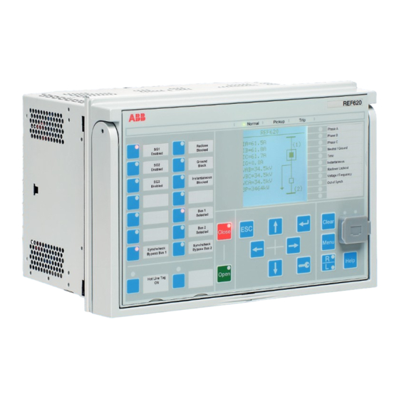
Front side of the IED GUID-C45202F5-7D53-421F-8245-4AEAFC3D13B2 V1 EN Figure 43: Large display Table 3: Large display Rows in the view Characters per row Character size Small, mono-spaced (6 × 12 pixels) 1) Depending on the selected language 620 series ANSI Installation Manual... -
Page 66: Rear Side Of The Ied
Section 7 1MAC457436-IB B Technical data 7.1.2 Rear side of the IED GUID-9E04AA0B-8DE9-41D7-8F62-9068ABA4DEAB V1 EN Figure 44: Rear view of REF620 with COM0011 and RTD002 modules 620 series ANSI Installation Manual... - Page 67 Section 7 1MAC457436-IB B Technical data GUID-E081EACE-6536-4A1A-A717-EEF7E0744BAF V1 EN Figure 45: Rear view of RET620 with COM0011 and RTD002 modules 620 series ANSI Installation Manual...
- Page 68 Protection relay's main dimensions 10.32 inches (262.2 mm) 6.97 inches (177 mm), 4U C 9.69 inches (246 mm) D 7.91 inches (201 mm) 6.02 inches (153 mm) 1.89 inches (48 mm) G 6.30 inches (160 mm) 620 series ANSI Installation Manual...
-
Page 69: Enclosure Class
7.91 inches (201 mm) Weight Complete protection relay max. 12.3 lbs (5.6 kg) Plug-in unit only 7.5 lbs (3.4 kg) Enclosure class Table 5: Degree of protection of flush-mounted protection relay Description Value Front side IP 54 620 series ANSI Installation Manual... -
Page 71: Section 8 Accessories And Ordering Data
1MAC457436-IB B Accessories and ordering data Section 8 Accessories and ordering data Table 6: Mounting accessories Item Order number Semi-flush mounting kit 2RCA030573A0001 Wall mounting kit 2RCA030894A0001 19" Mounting panel kit 2RCA031135A0001 Protection cover kit 2RCA030963A0001 620 series ANSI Installation Manual... -
Page 73: Section 9 Glossary
Light-emitting diode LHMI Local human-machine interface Polyamide Polybutylene terephthalate 1. Personal computer 2. Polycarbonate RoHS Restriction of the use of certain hazardous substances in electrical and electronic equipment Software Voltage transformer WHMI Web human-machine interface 620 series ANSI Installation Manual... - Page 76 Contact us ABB Inc. 4300 Coral Ridge Drive Coral Springs, Florida 33065, USA Phone +1 954 752 6700 +1 954 345 5329 Phone +1 800 222 1946 (Customer Service 24/7) www.abb.com/mediumvoltage www.abb.com/substationautomation...