
Related Manuals for ABB ACS800-02


Summary of Contents for ABB ACS800-02
- Page 1 ACS800 Hardware Manual ACS800-02 Drives (45 to 500 kW) ACS800-U2 Drives (60 to 600 HP)
-
Page 2: Acs800 Single Drive Manuals
ACS800-01/U1 Hardware Manual 0.55 to 110 kW (0.75 to 150 HP) 3AFE 64382101 (English) ACS800-02/U2 Hardware Manual 45 to 500 kW (60 to 600 HP) 3AFE 64567373 (English) ACS800-04/04M/U4 Hardware Manual 45 to 560 kW (60 to 600 HP) 3AFE 64671006 (English) - Page 3 ACS800-02 Drives 45 to 500 kW ACS800-U2 Drives 60 to 600 HP Hardware Manual 3AFE 64567373 Rev C EN EFFECTIVE: 18.11.2003 ã 2003 ABB Oy. All Rights Reserved.
-
Page 5: Safety Instructions
To which products this chapter applies This chapter applies to the ACS800-01/U1, the ACS800-02/U2 and the ACS800-04/ Use of warnings and notes There are two types of safety instructions throughout this manual: warnings and notes. -
Page 6: Installation And Maintenance Work
• ACS800-02 with enclosure extension: The main switch on the cabinet door does not remove the voltage from the input busbars of the drive. Before working on the drive, isolate the whole drive from the supply. -
Page 7: Grounding
In addition, connect the cable shields to protective earth (PE) in order to meet safety regulations. (ACS800-02: 360° high frequency grounding of cable entries is not required at the drive end.) •... -
Page 8: Mechanical Installation
ACS800-01: The drive is heavy. Do not lift it alone. Do not lift the unit by the front cover. Place the unit only on its back. ACS800-02, ACS800-04: The drive is heavy. Lift the drive by the lifting lugs only. Do not tilt the unit. The unit will overturn from a tilt of about 6 degrees. -
Page 9: Permanent Magnet Motor
Permanent magnet motor These are additional warnings concerning permanent magnet motor drives. WARNING! Do not work on the drive when the permanent magnet motor is rotating. Also, when the supply power is switched off and the inverter is stopped, a rotating permanent magnet motor feeds power to the intermediate circuit of the drive and the supply connections become live. - Page 10 Safety instructions...
-
Page 11: Table Of Contents
The ACS800-02/U2 ........ - Page 12 Emergency stop devices ............32 ACS800-02/U2 with enclosure extension and ACS800-07/U7 ......32 Restarting after an emergency stop .
- Page 13 To which products this chapter applies ..........69 Note for the ACS800-02 with enclosure extension and the ACS800-07 ..... 69 Note for external power supply .
- Page 14 RMIO board specifications ............72 Analogue inputs .
- Page 15 Optional brake chopper and resistor(s) for the ACS800-01/U1 ......120 Optional brake chopper and resistor(s) for the ACS800-02/U2, the ACS800-04/U4 and the ACS800-07/U7 .
-
Page 16: Table Of Contents
R8 (ACS800-02, ACS800-04, ACS800-07) ........ -
Page 17: About This Manual
Motor control and I/O board (RMIO) Resistor braking, apply to the ACS800-01/U1, the ACS800-02/U2, the ACS800-04/U4 and the ACS800-07/U7. Categorization according to the frame size Some instructions, technical data and dimensional drawings which concern only certain frame sizes are marked with the symbol of the frame size R2, R3... or R8. -
Page 18: Installation And Commissioning Flowchart
If the converter has been non-operational for equipment are present and correct. more than one year, the converter DC link capacitors need to be reformed. Ask ABB for Only intact units may be started up. instructions. Check the installation site. -
Page 19: Inquiries
Inquiries Address any inquiries about the product to the local ABB representative, quoting the type code and the serial number of the unit. If the local ABB representative cannot be contacted, address inquiries to the manufacturing facility (addresses and phone numbers are on the back cover of this manual). - Page 20 About this manual...
-
Page 21: The Acs800-02/U2
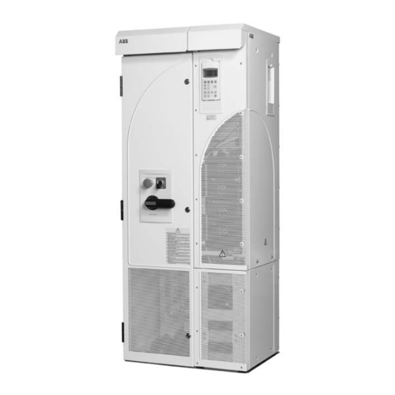
This chapter describes the construction and operating principle of the drive in short. The ACS800-02/U2 The ACS800-02 is a free-standing drive for controlling AC motors. In the basic unit, the cabling direction is from below. When an optional enclosure extension is connected next to the basic unit, the cables can also be led from above. -
Page 22: Enclosure Extension
Type code The type code contains information on the specifications and configuration of the drive. The first digits from left express the basic configuration (e.g. ACS800-02- 0170-5). The optional selections are given thereafter, separated by + signs (e.g. +E202). The main selections are described below. Not all selections are available for all types. - Page 23 Type code selections for the ACS800-02 Selection Alternatives Control panel 0J400 no control panel, LEDs on the panel mounting platform included L504 additional terminal block X2 (+C111 required) L505 thermistor relay (1 or 2 pcs, +C111 required) L506 Pt100 relay (3 pcs, +C111 required) L...
-
Page 24: Main Circuit And Control
Optional module 2: RTAC, RAIO or External control via RDIO analogue/digital inputs and outputs Optional module 3: RDCO-01, RDCO- 02 or RDCO-03 Input power Output power Brake chopper in frame sizes R2 and R3 (optional in other frame sizes) R- UDC+ UDC- The ACS800-02/U2... -
Page 25: Operation
Motor control The motor control is based on the Direct Torque Control (DTC) method. Two phase currents and DC link voltage are measured and used for the control. The third phase current is measured for earth fault protection. The ACS800-02/U2... - Page 26 The ACS800-02/U2...
-
Page 27: Planning The Electrical Installation
The stress on motor insulation can be avoided by using optional ABB du/dt filters. du/dt filters also reduce bearing currents. Planning the electrical installation... -
Page 28: Requirements Table
Requirements table The following table shows how to select the motor insulation system and when optional ABB du/dt filter, insulated N-end (non-driven end) motor bearings and ABB common mode filters are required. The motor manufacturer should be consulted regarding the construction of the motor insulation and additional requirements for explosion-safe (EX) motors. - Page 29 Motor type Nominal mains Requirement for voltage (AC line Motor insulation ABB du/dt filter, insulated N-end bearing and ABB common mode voltage) system filter < 100 kW 100 kW < P < 350 kW > 350 kW frame size > IEC 315 frame size <...
-
Page 30: Permanent Magnet Synchronous Motor
All AMA machines (manufactured in Helsinki) to be supplied by a drive have form-wound windings. All HXR machines manufactured in Helsinki since 1997 have form-wound windings. Note 5: ABB motors of types other than M2_, M3_, HX_ and AM_ Select according to non-ABB motors. -
Page 31: Fuses
(see Technical Data). ACS800-01/U1, ACS800-02/U2 without enclosure extension and ACS800-04/U4 When placed at the distribution board, standard gG (US: CC or T for the ACS800- U1; T or L for the ACS800-U2 and the ACS800-U4) fuses will protect the input cable in short-circuit situations, restrict drive damage and prevent damage to adjoining equipment in case of a short-circuit inside the drive. -
Page 32: Drive Ac Fuses (Acs800-07/U7 And Acs800-02/U2 With Enclosure Extension)
An emergency stop function is optionally available for stopping and switching off the whole drive. Two stop categories according to IEC/EN 60204-1 (1997) are available: immediate removal of power (Category 0 for ACS800-02/U2 and ACS800-07/U7) and controlled emergency stop (Category 1 for ACS800-07/U7). -
Page 33: Restarting After An Emergency Stop
Restarting after an emergency stop After an emergency stop, the emergency stop button must be released and the drive started by turning the operating switch of the drive from position “ON” to “START”. Prevention of Unexpected Start (ACS800-07/U7 only) The drive can be equipped with an optional Prevention of Unexpected Start function according to standards IEC/EN 60204-1: 1997;... -
Page 34: Selecting The Power Cables
Selecting the power cables General rules Dimension the mains (input power) and motor cables according to local regulations: • The cable must be able to carry the drive load current. See chapter Technical data for the rated currents. ° • The cable must be rated for at least 70 C maximum permissible temperature of conductor in continuous use. -
Page 35: Alternative Power Cable Types
Alternative power cable types Power cable types that can be used with the drive are represented below. Recommended Symmetrical shielded cable: three phase conductors A separate PE conductor is required if the conductivity and a concentric or otherwise symmetrically of the cable shield is < 50 % of the conductivity of the constructed PE conductor, and a shield phase conductor. -
Page 36: Additional Us Requirements
Additional US requirements Type MC continuous corrugated aluminum armor cable with symmetrical grounds or shielded power cable must be used for the motor cables if metallic conduit is not used. For the North American market, 600 VAC cable is accepted for up to 500 VAC. 1000 VAC cable is required above 500 VAC (below 600 VAC). -
Page 37: Equipment Connected To The Motor Cable
Equipment connected to the motor cable Installation of safety switches, contactors, connection boxes, etc. To minimize the emission level when safety switches, contactors, connection boxes or similar equipment are installed in the motor cable (i.e. between the drive and the motor): •... -
Page 38: Protecting The Relay Output Contacts And Attenuating Disturbances In Case Of Inductive Loads
Protecting the relay output contacts and attenuating disturbances in case of inductive loads Inductive loads (relays, contactors, motors) cause voltage transients when switched off. The relay contacts on the RMIO board are protected with varistors (250 V) against overvoltage peaks. In spite of this, it is highly recommended to equip inductive loads with noise attenuating circuits [varistors, RC filters (AC) or diodes (DC)] in order to minimize the EMC emission at switch-off. -
Page 39: Selecting The Control Cables
Control panel cable In remote use, the cable connecting the control panel to the drive must not exceed 3 metres (10 ft). The cable type tested and approved by ABB is used in control panel option kits. Planning the electrical installation... -
Page 40: Connection Of A Motor Temperature Sensor To The Drive I/O
Connection of a motor temperature sensor to the drive I/O WARNING! IEC 60664 requires double or reinforced insulation between live parts and the surface of accessible parts of electrical equipment which are either non- conductive or conductive but not connected to the protective earth. To fulfil this requirement, the connection of a thermistor (and other similar components) to the digital inputs of the drive can be implemented in three alternate ways:... -
Page 41: Control Cable Ducts
A diagram of the cable routing is below. Motor cable Drive min 300 mm (12 in.) Power cable Input power cable Motor cable 90 ° min 200 mm (8 in.) min 500 mm (20 in.) Control cables Control cable ducts 24 V 230 V 24 V 230 V... - Page 42 Planning the electrical installation...
-
Page 43: Installation
Installation What this chapter contains This chapter describes the mechanical and electrical installation procedure of the drive. WARNING! Only qualified electricians are allowed to carry out the work described in this chapter. Follow the Safety instructions on the first pages of this manual. Ignoring the safety instructions can cause injury or death. - Page 44 WARNING! The drive is heavy [frame size R7: 100 kg (220 lb) , frame size R8: 230 kg (507 lb)] . Lift the drive by the upper part only using the lifting lugs attached to the top of the unit. The lower part will be deformed from lifting. Do not remove the pedestal before lifting.
-
Page 45: Before Installation
Before installation Delivery check The drive is delivered in a box that also contains: • hardware manual • appropriate firmware manuals and guides • optional module manuals • delivery documents. Check that there are no signs of damage. Before attempting installation and operation, check the information on the type designation label of the drive to verify that the unit is of the correct type. -
Page 46: Requirements For The Installation Site
If a unit is mounted on the wall, the wall must be as close to vertical as possible, and strong enough to carry the weight of the unit. The drive must not be installed without the pedestal and a support shelf on wall, refer to ACS800-02/U2 Application Note on Wall Mounting [68250013 (English)]. -
Page 47: It (Ungrounded) Systems
(ungrounded systems). If the drive is equipped with EMC filter +E202, disconnect the filter before connecting the drive to an ungrounded system. For detailed instructions on how to do this, please contact your local ABB representative. WARNING! If a drive with EMC filter +E202 is installed on an IT system [an... -
Page 48: Power Cable Connection Diagram
Power cable connection diagram Drive module OUTPUT INPUT UDC+ V1 W1 V2 W2 (PE) (PE) * For alternatives, see Optional brake Planning the electrical resistor installation: Disconnecting Motor device (means) 1), 2) Grounding of the motor cable shield at the motor end If shielded cable is used (not required but For minimum radio frequency interference: recommended) and the conductivity of the shield is... -
Page 49: Installation Procedure
Installation procedure Choose the mounting orientation (a, b, c or d) Lifted from above With enclosure extension Symbols: required free space air inlet surface Note: The unit can also be installed away wall fixing point (recommended) from the wall. control panel mounting slot Frame Mounting Required free space around the unit for mounting, maintenance, service and cooling *... - Page 50 3. Undo the red M8 combi screws (8 pcs or 9 pcs with +D150) that connect the busbars of the pedestal to the upper frame. Use a torque wrench with an extension bar. 4. Wheel the drive frame out by using the handle. Wheeling the frame out 3 2 pcs ProE: ACS800-02-R7_manual2.drw Installation...
- Page 51 Remove the pedestal (frame size R8): 1. Remove the lower front covers by undoing the fixing screws. 2. Press the left support leg a little down and turn it left. Let it lock down. Turn the right leg aside in the same way. The legs will prevent the unit from falling down during the installation.
- Page 52 Fix the lead-through plate to the floor: 1. Make a hole in the floor or cable conduit cover below the lead-through plate. See Dimensional drawings. 2. Check that the floor is horizontal with a spirit level. 3. Fasten the lead-through plate with screws or bolts. Note: The screws/bolts will be removed and refastened when the pedestal is fastened through the same holes later on.
- Page 53 Prepare the power cables: 1. Strip the cables. 2. Twist the shield wires. 3. Bend the conductors to the terminals. 4. Cut the conductors to adequate length. Put the pedestal onto the lead-through plate and check the length of the conductors. Remove the pedestal. 5.
- Page 54 Frame size R8 64605569 Terminal hole 1 hole 2 hole 3 hole 1 hole 2 hole 3 Frame size R8 17.0 15.2 13.5 10.4 11.2 10.4 UDC- UDC+/R+ 10.4 PE terminal hole C / mm [in.] 24 [0.9] 56 [2.2] 88 [3.5] 120 [4.7] 152 [6.0] 184 [7.2] 216 [8.5] 248 [9.8] 280 [11.0] Lead the control cables through the lead-through plate: 1.
- Page 55 Connect the cable lugs to the pedestal: 1. If the lead-through plate is fixed to the floor, undo the fixing screws. 2. Place the pedestal onto the lead-through plate. 3. Fasten the pedestal and the lead-through plate to the floor with the screws through the same holes. 4.
-
Page 56: Mounting Orientation C (Lifting From Above)
• Fasten the lower front and side plates. • Fasten the drive by top to the wall (recommened). Note: When mounting the unit on wall, a support shelf is required, see the instructions in ACS800-02/U2 Application Note on Wall Mounting [68250013 (English)]. Installation... -
Page 57: Mounting Orientation D (Optional Enclosure Extension Included)
Mounting orientation d (optional enclosure extension included) The customer connections of the drive (power cable terminals, I/O terminal blocks, option module slots) are provided in the enclosure extension instead of the actual drive cubicle. The extension cubicle and the drive cubicle are fastened together at the factory with two screws at the top of the cubicles. -
Page 58: Connecting The Power Cables
Connecting the Power Cables Refer to Dimensional drawings for terminal locations and hole sizes. The same screw can be used for connecting two cable lugs (on both sides of the busbar). Procedure: • Lead the cables into the cubicle through the cable entries provided. Note: 360 degrees grounding is not needed at the cable entry. - Page 59 Bottom cable entry/exit (R7) Installation...
- Page 60 Top cable entry/exit (R7) Installation...
- Page 61 Bottom cable entry/exit (R8) Installation...
- Page 62 Top cable entry/exit (R8) Installation...
-
Page 63: Main Wiring Diagram
Main wiring diagram The diagram below presents the main wiring of the enclosure extension. Note that the diagram includes optional components (marked *) which are not always included in the delivery. Installation... -
Page 64: Routing The Control/Signal Cables Inside The Cubicle
Routing the control/signal cables inside the cubicle Units without an enclosure extension Frame size R7 Disconnect the control panel cables. Opening the top front cover (R7) Secure the cables with cable ties to the holes in the side bracket of the Frame size R8 capacitor pack. -
Page 65: Units With An Enclosure Extension
Units with an enclosure extension Cable entries with grommets for multiple cable diameters are provided. The following diagram gives an example of signal/control cabling routing inside the cubicle. RMIO Secure the cables with cable ties to these holes. Installation... -
Page 66: Connecting The Control Cables
Connecting the control cables Connect the control cables as described below. Connect the conductors to the appropriate detachable terminals of the RMIO board (refer to chapter Motor control and I/O board (RMIO)). Tighten the screws to secure the connection. Connecting the shield wires at RMIO board Strain relief Strain relief Insulation... -
Page 67: Settings Of The Cooling Fan Transformer
Settings of the cooling fan transformer The voltage transformer of the cooling fan (T41) is located at the top of the drive module. Set to 220 V if the supply frequency is 60 Hz. (The voltage is set to 230 V (50 Hz) at the factory.) Set according to the supply voltage: 380 V, 400 V, 415 V, 440 V, 480 V or 500 V;... -
Page 68: Pulse Encoder Module Cabling
Pulse encoder module cabling Clamp as close to the terminals as possible. Alternative to a) Note1: If the encoder is of unisolated As short as type, ground the encoder cable at the possible drive end only. If the encoder is Strain relief galvanically isolated from the motor with a cable tie... -
Page 69: Motor Control And I/O Board (Rmio)
Note for the ACS800-02 with enclosure extension and the ACS800-07 The connections for the RMIO board shown below apply also to optional terminal block X2 available for the ACS800-02 and the ACS800-07. The terminals of the RMIO board are wired to terminal block X2 internally. -
Page 70: External Control Connections (Non-Us)
AO1- AO2+ Output current 0(4)...20 mA 0...motor nom. current, R < 700 ohm AO2- * optional terminal block in ACS800-02 and ACS800-07 Stop/Start Forward/Reverse Only effective if par. 10.03 is set to REQUEST by the user. Not in use Acceleration & deceleration select... -
Page 71: External Control Connections (Us)
External control connections (US) External control cable connections to the RMIO board for the ACS800 Standard Application Program (Factory Macro US version) are shown below. For external control connections of other application macros and programs, see the appropriate Firmware Manual. RMIO RMIO VREF-... -
Page 72: Rmio Board Specifications
RMIO board specifications Analogue inputs With Standard Application Program two programmable differential current inputs (0 mA / 4 mA ... 20 mA, R = 100 ohm) and one programmable differential voltage input (-10 V / 0 V / 2 V ... +10 V, R >... -
Page 73: Relay Outputs
Maximum continuous current 2 A rms Isolation test voltage 4 kVAC, 1 minute DDCS fibre optic link With optional communication adapter module RDCO. Protocol: DDCS (ABB Distributed Drives Communication System) 24 VDC power input Voltage 24 VDC ± 10 %... - Page 74 Isolation and grounding diagram (Test voltage: 500 V AC) VREF- AGND VREF+ AGND AI1+ Common mode AI1- voltage between AI2+ channels ±15 V AI2- AI3+ AI3- AO1+ AO1- AO2+ AO2- Jumper J1 settings: DGND1 All digital inputs share a common ground.
-
Page 75: Installation Checklist
Installation checklist Checklist Check the mechanical and electrical installation of the drive before start-up. Go through the checklist below together with another person. Read the Safety instructions on the first pages of this manual before you work on the unit. Check MECHANICAL INSTALLATION The ambient operating conditions are allowed. - Page 76 Installation checklist...
-
Page 77: Maintenance
Note: There are parts carrying dangerous voltages near the RMIO board when the drive is powered. Maintenance intervals If installed in an appropriate environment, the drive requires very little maintenance. This table lists the routine maintenance intervals recommended by ABB. Interval Maintenance Instruction... -
Page 78: Layout
Layout The layout stickers of the drive are shown below. The stickers show all possible components. Not all of them are present in each delivery or described here. Designation Component Control panel Motor control and I/O board (RMIO) Cooling fan Capacitors Code: 64572261-B Code: 64601423-B... -
Page 79: Heatsink
A cooling fan is included in the enclosure extension with a contactor option. Its lifespan is at least 40 000 h. Replacement fans are available from ABB. Do not use other than ABB specified spare parts. Maintenance... -
Page 80: Replacing The Fan Of The Enclosure Extension
Replacing the fan of the enclosure extension The fan is fastened to the inside of the roof. Remove the fan as follows: 1. Disconnect the fan wires. 2. Loosen the six fixing screws of the fan cassette. 3. Shift the fan cassette sideways and pull it out of the enclosure extension. 4. -
Page 81: Replacing The Fan (R7)
Replacing the fan (R7) 1. Remove the upper front cover and disconnect the control panel cables. 2. Disconnect the discharging resistor wire. 3. Remove the DC capacitor pack by undoing the red fixing screws and pulling the pack out. 4. Disconnect the fan supply wires (detachable connector). 5. -
Page 82: Replacing The Fan (R8)
Replacing the fan (R8) 1. Remove the front covers by undoing the fixing screws and disconnecting the control panel cable. 2. Disconnect the fan capacitor and power supply wires. 3. Remove the fan capacitor. 4. Units without enclosure extension: disconnect the power supply (a), fibre optic (b) and control panel (c) cables from the RMIO board. -
Page 83: Capacitors
It is not possible to predict a capacitor failure. Capacitor failure is usually followed by damage to the unit and an input cable fuse failure, or a fault trip. Contact ABB if capacitor failure is suspected. Replacements are available from ABB. Do not use other than ABB specified spare parts. -
Page 84: Replacing The Capacitor Pack (R8)
Replacing the capacitor pack (R8) 1. Remove the upper front covers and disconnect the control panel cable. Remove the side plate equipped with the control panel mounting slot. 2. Disconnect the discharging resistor wires. 3. Undo the fastening screws. 4. Lift the capacitor pack out. 5. -
Page 85: Module Replacement Of Units With The Enclosure Extension
Module replacement of units with the enclosure extension 1. Remove the upper front cover and disconnect the control panel cables. 2. Remove the lower front cover. 3. Undo the fastening screws of the pedestal. 4. Disconnect the pedestal from the drive module by undoing the connection screws. -
Page 86: Leds
LEDs This table describes LEDs of the drive. Where When the LED is lit RMIO board Drive in fault state Green The power supply on the board is OK. Control panel mounting platform Drive in fault state Green The main + 24 V power supply for the control panel and the RMIO board is OK. -
Page 87: Technical Data
CE and other markings, and warranty policy. IEC ratings The IEC ratings for the ACS800-02 with 50 Hz and 60 Hz supplies are given below. The symbols are described below the table. ACS800-02... -
Page 88: Symbols
50 % overload is available for one minute every 5 minutes if ambient temperature is less than 25 °C. If ambient temperature is 40 °C, max. available overload is 37 %. 50 % overload is available for one minute every 5 minutes if ambient temperature is less than 30 °C. If ambient temperature is 40 °C, max. -
Page 89: Derating
At altitudes from 1000 to 4000 m (3281 to 13123 ft) above sea level, the derating is 1 % for every 100 m (328 ft). For a more accurate derating, use the DriveSize PC tool. If the installation site is higher than 2000 m (6562 ft) above sea level, please contact your local ABB distributor or office for further information. -
Page 90: Mains Cable Fuses
Note 1: In multicable installations, install only one fuse per phase (not one fuse per conductor). Note 2: Larger fuses must not be used. Note 3: Fuses from other manufacturers can be used if they meet the ratings. Standard gG fuses ACS800-02 Input Fuse size... -
Page 91: Ultrarapid (Ar) Fuses
Ultrarapid (aR) fuses ACS800-02 Input Fuse size current Manufacturer Type DIN 43620 Size Three-phase supply voltage 208 V, 220 V, 230 V or 240 V -0080-2 105 000 Bussmann 170M3819 DIN1* -0100-2 145 000 Bussmann 170M5810 DIN2* -0120-2 190 000... -
Page 92: Cable Types
Cable types The table below gives copper and aluminium cable types for different load currents. Cable sizing is based on max. 9 cables laid on a cable ladder side by side, ambient temperature 30 °C, PVC insulation, surface temperature 70 °C (EN 60204-1 and IEC 60364-5-2/2001). -
Page 93: Cable Entries
Cable entries Mains, motor and brake resistor cable terminal sizes (per phase), maximum accepted cable diameters and tightening torques are given below . The maximum allowed width of the cable lug is 38 mm. Frame U1, V1, W1, U2, V2, W2, UDC+/R+, UDC-, R- Earthing PE size Number of holes per... -
Page 94: Motor Connection
Motor connection Voltage (U 0 to U , 3-phase symmetrical, U at the field weakening point Frequency DTC mode: 0 to 3.2 · f . Maximum frequency 300 Hz. Nmains · f Nmotor Nmotor : frequency at field weakening point; U : mains (input power) voltage;... -
Page 95: Ambient Conditions
Ambient conditions Environmental limits for the drive are given below. The drive is to be used in a heated, indoor, controlled environment. Operation Storage Transportation installed for stationary use in the protective package in the protective package Installation site altitude 0 to 4000 m (13123 ft) above sea level [above 1000 m (3281 ft), see section... -
Page 96: Materials
For further information on environmental aspects and more detailed recycling instructions, please contact your local ABB distributor. Applicable standards The drive complies with the following standards. The compliance with the European Low Voltage Directive is verified according to standards EN 50178 and EN 60204-1. -
Page 97: Ce Marking
CE marking A CE mark is attached to the drive to verify that the unit follows the provisions of the European Low Voltage and EMC Directives (Directive 73/23/EEC, as amended by 93/68/EEC and Directive 89/336/ EEC, as amended by 93/68/EEC). Definitions EMC stands for Electromagnetic Compatibility. -
Page 98: Second Environment
Equipment 2. An EMC plan for preventing disturbances is drawn up for the installation. A template is available from the local ABB representative. 3. The motor and control cables are selected as specified in the Hardware Manual. 4. The drive is installed according to the instructions given in the Hardware Manual. -
Page 99: C-Tick" Marking
“C-tick” marking “C-tick” marking is pending as follows. “C-tick” marking is required in Australia and New Zealand. A “C-tick” mark is attached to each drive in order to verify compliance with the relevant standard (IEC 61800-3 (1996) – Adjustable speed electrical power drive systems –... -
Page 100: Second Environment
In no event shall the manufacturer, its suppliers or subcontractors be liable for special, indirect, incidental or consequential damages, losses or penalties. If you have any questions concerning your ABB drive, please contact the local distributor or ABB office. The technical data, information and specifications are valid at the time of printing. The manufacturer reserves the right to modifications without prior notice. -
Page 101: Us Tables
US tables NEMA ratings The NEMA ratings for the ACS800-U2 with 60 Hz supplies are given below. The symbols are described below the table. For sizing, derating and 50 Hz supplies, see ratings. ACS800-U2 size Normal use Heavy-duty use Frame Air flow Heat size... -
Page 102: Symbols
Symbols maximum output current. Available for 10 s ar start, otherwise as long as allowed by drive temperature. Normal use (10 % overload capability) continuous rms current. 10 % overload is typically allowed for one minute every 5 minutes. typical motor power. The power ratings apply to most 4-pole NEMA rated motors (230 V or 460 V). -
Page 103: Ultrarapid (Ar) Fuses
ACS800-U2 type Input Fuse current Manufacturer Type UL class Three-phase supply voltage 380 V, 400 V, 415 V, 440 V, 460 V, 480 V -0170-5 Bussmann JJS-250 -0210-5 Bussmann JJS-300 -0260-5 Bussmann JJS-400 -0270-5 Bussmann JJS-500 -0300-5 Bussmann JJS-500 -0320-5 Bussmann JJS-500 -0400-5... -
Page 104: Cable Types
Cable types Cable sizing is based on NEC Table 310-16 for copper wires, 75 °C (167 °F) wire insulation at 40 °C (104 °F) ambient temperature. Not more than three current-carrying conductors in raceway or cable or earth (directly buried). For other conditions, dimension the cables according to local safety regulations, appropriate input voltage and the load current of the drive. -
Page 105: Dimensions And Weights
UL/CSA markings The ACS800-02 and the ACS800-U2 are C-UL US listed and CSA marked. The approvals are valid with rated voltages (up to 600 V). The drive is suitable for use on a circuit capable of delivering not more than 65 kA rms symmetrical amperes at the drive nominal voltage (600 V maximum for 690 V units). - Page 106 Technical data...
-
Page 107: Dimensional Drawings
Dimensional drawings The dimensions are given in milllimetres and [inches]. Dimensional drawings... -
Page 108: Frame Size R7
Frame size R7 Dimensional drawings... -
Page 109: Frame Size R8
Frame size R8 Dimensional drawings... -
Page 110: Frame Size R7 With Enclosure Extension - Bottom Entry
Frame size R7 with enclosure extension – bottom entry Dimensional drawings... - Page 111 Dimensional drawings...
-
Page 112: Frame Size R7 With Enclosure Extension - Top Entry
Frame size R7 with enclosure extension – top entry Dimensional drawings... - Page 113 Dimensional drawings...
-
Page 114: Frame Size R8 With Enclosure Extension - Bottom Entry
Frame size R8 with enclosure extension – bottom entry Dimensional drawings... - Page 115 Dimensional drawings...
-
Page 116: Frame Size R8 With Enclosure Extension - Top Entry
Frame size R8 with enclosure extension – top entry Dimensional drawings... - Page 117 Dimensional drawings...
- Page 118 Dimensional drawings...
-
Page 119: Resistor Braking
The chapter also contains the technical data. To which products this chapter applies This chapter applies to the ACS800-01/U1 (frame sizes R2 to R6), the ACS800-02/ U2 (frame sizes R7 and R8), the ACS800-04/U4 (frame sizes R7 and R8) and the ACS800-07/U7 (frame sizes R6, R7 and R8). -
Page 120: Optional Brake Chopper And Resistor(S) For The Acs800-01/U1
Note: A resistor other than the standard resistor can be used provided that: • its resistance is not lower than the resistance of the standard resistor. WARNING! Never use a brake resistor with a resistance below the value specified for the particular drive / brake chopper / resistor combination. The drive and the chopper are not able to handle the overcurrent caused by the low resistance. - Page 121 ACS 800-01 type Braking power of Brake resistor(s) the chopper and the drive Type brcont Rcont (kW) (ohm) (kJ) (kW) 400 V units -0003-3 SACE08RE44 -0004-3 SACE08RE44 -0005-3 SACE08RE44 -0006-3 SACE08RE44 -0009-3 SACE08RE44 -0011-3 SACE15RE22 -0016-3 SACE15RE22 -0020-3 SACE15RE22 -0025-3 SACE15RE13 -0030-3 SACE15RE13...
-
Page 122: Optional Brake Chopper And Resistor(S) For The Acs800-02/U2, The Acs800-04/U4 And The Acs800-07/U7
Optional brake chopper and resistor(s) for the ACS800-02/U2, the ACS800-04/U4 and the ACS800-07/U7 ACS 800 type Frame Braking power of the chopper and the Brake resistor(s) size drive 5/60 s 10/60 s 30/60 s Type Rcont (ohm) (kJ) (kW) br10... - Page 123 Maximum braking power of the drive with the specified resistor(s). The drive and the chopper will withstand this braking power for 5 seconds per minute. The drive and the chopper will withstand this braking power for 10 seconds per minute. br10 The drive and the chopper will withstand this braking power for 30 seconds per minute.
-
Page 124: Resistor Installation And Wiring
Combined braking cycles for R7: Examples max 5 s or 10 s or P br10 br30 brcont No braking max 30 s min. 30 s min. 30 s max 30 s min. 30 s • After P or P braking, the drive and the chopper will withstand P continuously. -
Page 125: Acs800-07/U7
Note: If an external brake chopper (outside the drive module) is used, a main contactor is always required. A thermal switch (standard in ABB resistors) is required for safety reasons. The cable must be shielded and not longer than the resistor cable. -
Page 126: Brake Circuit Commissioning
OFF2 STOP. For the use of the brake resistor overload protection (parameters 27.02...27.05), consult an ABB representative. WARNING! If the drive is equipped with a brake chopper but the chopper is not enabled by parameter setting, the brake resistor must be disconnected because the protection against resistor overheating is then not in use. - Page 128 ABB Oy ABB Inc. AC Drives Automation Technologies P.O. Box 184 Drives and Motors FIN-00381 HELSINKI 16250 West Glendale Drive FINLAND New Berlin, WI 53151 Telephone +358 10 22 11 +358 10 22 22681 Telephone 262 785-3200 Internet http://www.abb.com 800-HELP-365...