Siemens SINAMICS G120 Original Instructions Manual
Sinamics g120 inverter with cu230p-2 control
units
Hide thumbs
Also See for SINAMICS G120:
- List manual (1256 pages) ,
- Manual (732 pages) ,
- Operating instructions manual (550 pages)
Table of Contents
Quick Links
Table of Contents

Related Manuals for Siemens SINAMICS G120


Summary of Contents for Siemens SINAMICS G120
- Page 3 ___________________ Inverter with CU230P-2 Control Units Change history ___________________ Safety notes ___________________ Introduction SINAMICS ___________________ Description SINAMICS G120 ___________________ Inverter with CU230P-2 Control Installing Units ___________________ Commissioning Operating Instructions ___________________ Adapting the terminal strip ___________________ Configuring the fieldbus ___________________ Setting functions...
- Page 4 Note the following: WARNING Siemens products may only be used for the applications described in the catalog and in the relevant technical documentation. If products and components from other manufacturers are used, these must be recommended or approved by Siemens. Proper transport, storage, installation, assembly, commissioning, operation and maintenance are required to ensure that the products operate safely and without any problems.
-
Page 5: Change History
Change history Important changes with respect to the Manual, Edition 03/2012 New Power Modules In Chapter Power Module PM330 GX with IP20 degree of protection Power Modules in degree of protection • IP20 and with push-through system (Page 28) An overview of all new and modified functions in firmware V4.6.6 can be found in Section New and extended functions (Page 411). - Page 6 Change history Inverter with CU230P-2 Control Units Operating Instructions, 11/2013, FW V4.6.6, A5E02430659B AG...
-
Page 7: Table Of Contents
Table of contents Change history ............................5 Safety notes ............................15 General safety instructions ......................15 Safety instructions for electromagnetic fields (EMF) ..............19 Handling electrostatic sensitive devices (ESD) ................19 Residual risks of power drive systems ..................20 Introduction ............................23 About this manual ........................ - Page 8 Table of contents Connecting inverters in compliance with EMC................67 4.5.1 EMC-compliant connection of the converter ................67 4.5.2 Avoid electromagnetic interference (EMI) ................... 68 Commissioning ............................. 73 Commissioning guidelines ......................73 Preparing for commissioning....................... 74 5.2.1 Wiring examples for the factory settings ..................75 5.2.2 Does the motor match the converter? ..................
- Page 9 Table of contents 7.3.1.5 Slave-to-slave communication ....................129 7.3.2 Acyclic communication ....................... 130 PROFIenergy profile for PROFINET ..................135 Communication via EtherNet/IP ....................137 7.5.1 Connect converter to Ethernet/IP....................137 7.5.2 What do you need for communication via Ethernet/IP?............. 138 7.5.3 Communication settings for Ethernet/IP ..................
- Page 10 Table of contents Setting functions ..........................225 Overview of the inverter functions ..................... 225 Inverter control .......................... 227 8.2.1 Switching the motor on and off ....................227 8.2.2 Two-wire control: method 1 ....................... 230 8.2.3 Two-wire control, method 2 ....................... 231 8.2.4 Two-wire control, method 3 .......................
- Page 11 Table of contents 8.7.3.4 Dynamic braking ........................280 8.7.3.5 Braking with regenerative feedback to the line ................283 8.7.4 Automatic restart and flying restart .................... 284 8.7.4.1 Flying restart – switching on while the motor is running ............284 8.7.4.2 Automatic switch-on ........................
- Page 12 Table of contents Alarms, faults and system messages ....................355 11.1 Operating states indicated on LEDs ..................356 11.2 System runtime ......................... 358 11.3 Alarms ............................359 11.4 Faults ............................362 11.5 List of alarms and faults ......................366 Technical data ............................. 373 12.1 Technical data for CU230P-2 ....................
- Page 13 Table of contents A.5.2 Optimize the drive using the trace function ................422 Interconnecting signals in the converter ..................425 A.6.1 Fundamentals ..........................425 A.6.2 Example ............................. 427 Application examples ......................... 429 A.7.1 Configuring PROFIBUS communication in STEP 7..............429 A.7.1.1 Creating a STEP 7 project and network ..................
- Page 14 Table of contents Inverter with CU230P-2 Control Units Operating Instructions, 11/2013, FW V4.6.6, A5E02430659B AG...
-
Page 15: Safety Notes
Safety notes Use for the intended purpose The inverter described in this manual is a device for controlling an induction motor. The inverter is designed for installation in electrical installations or machines. It has been approved for industrial and commercial use on industrial networks. Additional measures have to be taken when connected to public grids. - Page 16 Safety notes 1.1 General safety instructions WARNING Danger to life through a hazardous voltage when connecting an unsuitable power supply Death or serious injury can result when live parts are touched in the event of a fault. • Only use power supplies that provide SELV (Safety Extra Low Voltage) or PELV- (Protective Extra Low Voltage) output voltages for all connections and terminals of the electronics modules.
- Page 17 Safety notes 1.1 General safety instructions WARNING Danger to life due to fire spreading if housing is inadequate Fire and smoke development can cause severe personal injury or material damage. • Install devices without a protective housing in a metal control cabinet (or protect the device by another equivalent measure) in such a way that contact with fire inside and outside the device is prevented.
- Page 18 Safety notes 1.1 General safety instructions WARNING Danger of an accident occuring due to missing or illegible warning labels Missing or illegible warning labels can result in death or serious injury. • Check the warning labels are complete based on the documentation. •...
-
Page 19: Safety Instructions For Electromagnetic Fields (Emf)
Safety notes 1.2 Safety instructions for electromagnetic fields (EMF) Safety instructions for electromagnetic fields (EMF) WARNING Danger to life from electromagnetic fields Electromagnetic fields (EMF) are generated by the operation of electrical power equipment such as transformers, converters or motors. People with pacemakers or implants are at a special risk in the immediate vicinity of these devices/systems. -
Page 20: Residual Risks Of Power Drive Systems
Safety notes 1.4 Residual risks of power drive systems Residual risks of power drive systems The control and drive components of a drive system are approved for industrial and commercial use in industrial line supplies. Their use in public line supplies requires a different configuration and/or additional measures. - Page 21 Safety notes 1.4 Residual risks of power drive systems 3. Hazardous shock voltages caused by, for example: – Component malfunctions – Influence of electrostatic charging – Induction of voltages in moving motors – Operating and/or ambient conditions outside of the specification –...
- Page 22 Safety notes 1.4 Residual risks of power drive systems This product contains software that has been developed by the OpenSSL project for use in the OpenSSL toolkit. (See also http://www.openssl.org (http://www.openssl.org/)) Inverter with CU230P-2 Control Units Operating Instructions, 11/2013, FW V4.6.6, A5E02430659B AG...
-
Page 23: Introduction
Introduction About this manual Who requires the operating instructions and what for? These operating instructions primarily address fitters, commissioning engineers and machine operators. The operating instructions describe the devices and device components and enable the target groups being addressed to install, connect-up, set, and commission the converters safely and in the correct manner. -
Page 24: Guide Through This Manual
Introduction 2.2 Guide through this manual Guide through this manual In this manual, you will find background information on your inverter, as well as a full description of the commissioning procedure: ① Here you will find information about the hardware of your inverter and the commissioning tools: •... -
Page 25: Description
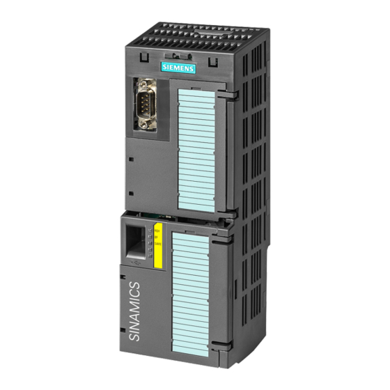
All power data refers to rated values or to power for operation with low overload (LO). Identifying the converter Main components of the inverter Each SINAMICS G120 inverter comprises a Control Unit and a Power Module. • The Control Unit controls and monitors the Power Module and the connected motor. - Page 26 Description 3.1 Identifying the converter Further inverter components The following components are available so that you can adapt the inverter to different applications and ambient conditions: ● Line filter (Page 32) ● Line reactor (Page 33) ● Output reactor (Page 34) ●...
-
Page 27: Control Units
The I/O interfaces, the fieldbus interface and the specific software functions optimally support these applications. The integration of technological functions is a significant differentiating feature to the other Control Units of the SINAMICS G120 drive family. CU230P-2-specific functions ●... -
Page 28: Power Module
Description 3.3 Power Modules Power Modules Which Power Module can I use with the Control Unit? You can operate the CU230P-2 Control Unit with the following Power Modules: ● PM230 ● PM330 ● PM240 ● PM240-2 ● PM250 ● PM260 3.3.1 Power Modules in degree of protection IP20 and with push-through system 3.3.1.1... - Page 29 Description 3.3 Power Modules PM230, 3 AC 400 V - Pump and fan applications The PM230 Power Module is available without a filter or with integrated class A line filter. Range of order numbers: 6SL3210-1NE… • IP20: 6SL3211-1NE… • Push-through Frame size Power range (kW), IP20 0,37 …...
-
Page 30: Accessories For Installation And Shielding
Description 3.3 Power Modules PM250, 3 AC 400 V - Application areas with line regeneration The PM250 Power Module is available without a filter or with an integrated class A line filter with degree of protection IP20. The PM250 permits dynamic braking with energy feedback into the line supply. -
Page 31: Power Modules In Ip55 Degree Of Protection / Ul Type 12
Description 3.3 Power Modules Order numbers for shield connection kit and DIN rail mounting adapter Frame size Shield connection kit for Power Modules Adapter for mounting on DIN rails PM240, PM250 PM260 6SL3262-1AA00-0BA0 6SL3262-1BA00-0BA0 6SL3262-1AB00-0DA0 6SL3262-1BB00-0BA0 6SL3262-1AC00-0DA0 6SL3262-1AD00-0DA0 6SL3262-1FD00-0CA0 6SL3262-1AD00-0DA0 6SL3262-1AF00-0DA0 6SL3262-1FF00-0CA0 3.3.2... -
Page 32: System Components For The Power Modules
Description 3.4 System components for the Power Modules System components for the Power Modules 3.4.1 Line filter With a line filter, the inverter can achieve a higher radio interference class. An external filter is not required for inverters with integrated line filter. Adjacent examples of line filters. -
Page 33: Line Reactor
Description 3.4 System components for the Power Modules 3.4.2 Line reactor The line reactor supports the overvoltage protection, smoothes the harmonics in the line supply and bridges commutation dips. For the Power Modules subsequently listed, a line reactor is suitable in order to dampen the specified effects. Adjacent examples of line reactors. -
Page 34: Output Reactor
Description 3.4 System components for the Power Modules Line reactors for PM240-2 Power Module 6SL321⃞-… Power Line reactor …1PE11-8⃞L0, …1PE12-3⃞L0, 0.55 kW … 1.1 kW 6SL3203-0CE13-2AA0 …1PE13-2⃞L0 …1PE14-3⃞L0, …1PE16-1⃞L0, 1.5 kW … 3.0 kW 6SL3203-0CE21-0AA0 …1PE18-0⃞L0 Line reactors for PM330 Power Module 6SL3310-…... - Page 35 Description 3.4 System components for the Power Modules Output reactors for PM240 Power Module Power Module 6SL3224-… Power Output reactor …0BE13-7UA0, …0BE15-5UA0, 0.37 kW … 1.5 kW 6SE6400-3TC00-4AD2 …0BE17-5UA0, …0BE21-1UA0, …0BE21-5UA0 …0BE22-2⃞A0, …0BE23-0⃞A0, 2.2 kW … 4.0 kW 6SL3202-0AE21-0CA0 …0BE24-0⃞A0 …0BE25-5⃞A0, …0BE27-5⃞A0, 7.5 kW …...
-
Page 36: Sine-Wave Filter
Description 3.4 System components for the Power Modules 3.4.4 Sine-wave filter The sine-wave filter at the inverter outputs almost sinusoidal voltages to the motor, so that you can use standard motors without special cables. The maximum permissible length of motor feeder cables is increased to 300 m. -
Page 37: Dv/Dt Filter
Description 3.4 System components for the Power Modules Sine-wave filter for PM250 Power Module Power Modul 6SL3225-… Power Sine-wave filter …0BE25-5⃞A0 7.5 kW 6SL3202-0AE22-0SA0 …0BE27-5⃞ A0, …0BE31-1⃞A0 11.0 kW … 15.0 kW 6SL3202-0AE23-3SA0 …0BE31-5⃞A0, …0BE31-8⃞A0 18.5 kW … 22 kW 6SL3202-0AE24-6SA0 …0BE32-2⃞A0 30 kW... - Page 38 Description 3.4 System components for the Power Modules Braking resistors for PM240 Power Module Braking Module Braking resistor 6SL3224-… Power 6SL3300-… Power …0BE13-7UA0, 0.37 kW … 1.5 kW 6SE6400-4BD11-0AA0 …0BE15-5UA0, …0BE17-5UA0, …0BE21-1UA0, …0BE21-5UA0 …0BE22-2⃞A0, 2.2 kW … 4.0 kW 6SL3201-0BE12-0AA0 …0BE23-0⃞A0, …0BE24-0⃞A0 …0BE25-5⃞A0,...
-
Page 39: Tools To Commission The Converter
STARTER Commissioning tool (PC software) STARTER on DVD: Connection to the inverter via USB port, PROFIBUS or 6SL3072-0AA00-0AG0 PROFINET Downloading: STARTER (http://support.automation.siemens.com/WW/view/en/1080498 5/133200) Drive ES Basic 6SW1700-5JA00-5AA0 As an option to STEP 7 with routing function via network limits for PROFIBUS and PROFINET Inverter with CU230P-2 Control Units Operating Instructions, 11/2013, FW V4.6.6, A5E02430659B AG... - Page 40 Description 3.5 Tools to commission the converter Inverter with CU230P-2 Control Units Operating Instructions, 11/2013, FW V4.6.6, A5E02430659B AG...
-
Page 41: Installing
2. Install the Power Module. See also Installing Power Module (Page 43). You can find information about your Power Module in the corresponding Hardware Installation Manual (http://support.automation.siemens.com/WW/view/en /30563173/133300). 3. Install the Control Unit. See also Installing Control Unit (Page 58). -
Page 42: Installing Reactors, Filters And Braking Resistors
Installing 4.2 Installing reactors, filters and braking resistors Installing reactors, filters and braking resistors Installing reactors, filters and braking resistors The installation of reactors, filters and braking resistors is described in the documentation provided. See also Section: Additional information on the inverter (Page 446). Installing base components Reactors, filters and braking resistors are available as base components for the PM240 and PM250 Power Modules, frame sizes FSA, FSB and FSC. -
Page 43: Installing Power Module
Installing 4.3 Installing Power Modules Installing Power Modules WARNING Danger of fire spreading due to inadequate housing Fire and smoke development can cause severe personal injury or material damage. • Install devices without a protective housing in a metal control cabinet (or protect the device by another equivalent measure) in such a way that contact with fire inside and outside the device is prevented. - Page 44 Installing 4.3 Installing Power Modules Mounting Power Modules using through-hole technology We recommend that you use the optionally available mounting frame to mount the push- through unit in a control cabinet. This mounting frame includes the necessary seals and frame to ensure compliance with degree of protection IP54. If you do not use the optional mounting frames, then you must ensure that the required degree of protection is complied with using other appropriate measures.
-
Page 45: Dimensions, Hole Drilling Templates, Minimum Clearances, Tightening Torques
Installing 4.3 Installing Power Modules 4.3.1 Dimensions, hole drilling templates, minimum clearances, tightening torques Dimensions and drilling patterns for the PM230 Power Modules, IP55 Table 4- 1 Dimensions and clearances for the PM230, IP55 Frame Dimensions (mm) Clearances (mm) size Height Width Depth... - Page 46 Installing 4.3 Installing Power Modules Dimensions and drilling patterns for Power Modules with IP20 degree of protection Drilling patterns for the PM240, PM250 and PM260 Power Modules FSB…FSF FSGX Drilling patterns for the PM230 and PM240-2 Power Modules FSB, FSC Inverter with CU230P-2 Control Units Operating Instructions, 11/2013, FW V4.6.6, A5E02430659B AG...
- Page 47 Installing 4.3 Installing Power Modules Table 4- 3 Dimensions and clearances for the PM240 Frame size Dimensions (mm) Clearances (mm) Height Width Depth bottom lateral 36.5 FSD without filter FSD with filter FSE without filter FSE with filter FSF without filter FSF with filter FSGX 1533...
- Page 48 Installing 4.3 Installing Power Modules Table 4- 6 Mounting hardware for PM250 Frame size Material Tightening torque M5 screws 2.5 Nm FSD, FSE M6 screws 6 Nm M8 screws 13 Nm Table 4- 7 Dimensions and clearances for the PM260 Frame size Dimensions (mm) Clearances (mm)
- Page 49 Installing 4.3 Installing Power Modules Dimensions and drilling patterns for Power Modules with through-hole technology Mounting cutout in the control cabinet for the PM230 and PM240-2 Power Modules; Holes for fastening the mounting frame FSA, FSB Table 4- 9 Dimensions and clearances for PM230 in through-hole technology, FSA … FSC Frame size Dimensions (mm) Clearances (mm)
- Page 50 Installing 4.3 Installing Power Modules Table 4- 11 Dimensions and clearances for PM240-2 in through-hole technology, FSA … FSC Frame Dimensions (mm) Clearances (mm) size Height Width Depth Bottom Lateral 147.5 34.5 30.5 With shield connection kit: FSA: +84 mm; FSB: +85 mm; FSC: +89 mm You can mount the mounting frames without any lateral clearance.
-
Page 51: Connecting The Line Supply, Motor And Converter Components
Installing 4.3 Installing Power Modules 4.3.2 Connecting the line supply, motor and converter components Figure 4-2 Connecting the PM230 IP20 and push-through Power Module The line filter of Power Module PM230 fulfills Class A. For higher EMC requirements, you need an external Class B line filter. Figure 4-3 Connecting the PM230 IP55 Power Module Either a Class A or a Class B filter is integrated in the Power Module PM230 IP55. - Page 52 Installing 4.3 Installing Power Modules Figure 4-4 Connecting the PM240, PM240-2 IP20 and push-through Power Module PM240 and PM240-2 Power Modules are available with and without integrated Class A line filters. For higher EMC requirements you need an external Class B line filter. Figure 4-5 Connecting the PM250 Power Module PM250 Power Modules are available with and without integrated Class A line filters.
- Page 53 Installing 4.3 Installing Power Modules Figure 4-6 Connecting the PM260 Power Module PM260 Power Modules are available with and without integrated Class A line filters. For higher EMC requirements you need an external Class B line filter. Figure 4-7 Connecting the PM330 Power Module Inverter with CU230P-2 Control Units Operating Instructions, 11/2013, FW V4.6.6, A5E02430659B AG...
-
Page 54: Power Distribution Systems
Installing 4.3 Installing Power Modules 4.3.2.1 Power distribution systems The inverter is designed for the following power distribution systems according to EN 60950. TN-S system TN-C-S system TN-C system TT system IT system In a TN-S system, In a TN-C-S system, In a TN-C system, the In a TT system, one An IT line supply does... - Page 55 Installing 4.3 Installing Power Modules DANGER ((Electric shock through contact with the motor connections)) As soon as the converter is connected to the line supply, the motor connections of the converter may carry dangerous voltages. When the motor is connected to the converter, there is danger to life through contact with the motor terminals if the terminal box is open.
- Page 56 Installing 4.3 Installing Power Modules Connecting the line supply cable to the converter Procedure To connect the converter to the supply system, proceed as follows: 1. If available, open the terminal covers of the converter. 2. Connect the line supply to terminals U1/L1, V1/L2, and W1/L3. 3.
- Page 57 Installing 4.3 Installing Power Modules Permissible cable lengths The permissible cables and cable lengths are specified in the Hardware Installation Manual of the Power Module or in Catalog D31. Note • Please observe the data on the rating plate (type plate) and the associated circuit diagrams.
-
Page 58: Installing Control Unit
Installing 4.4 Installing Control Unit Installing Control Unit Installing the Control Unit on an IP20 Power Module Procedure Proceed as follows to connect Power Modules and Control Units: 1. Locate the lugs at the rear of the Control Unit in the matching recesses of the Power Module. - Page 59 Installing 4.4 Installing Control Unit Procedure for removing a Control Unit Please proceed as follows: 1. Ensure that the device is disconnected from the power supply. 2. Unscrew the cover of the power section. 3. Depending on the Power Module: –...
-
Page 60: Interfaces, Connectors, Switches, Control Terminals, Leds On The Cu
Installing 4.4 Installing Control Unit 4.4.1 Interfaces, connectors, switches, control terminals, LEDs on the CU Interfaces at the front of the Control Unit To access the interfaces at the front of the Control Unit, you must lift the Operator Panel (if one is being used) and open the front doors. - Page 61 Installing 4.4 Installing Control Unit Interfaces on the lower side of the Control Unit Inverter with CU230P-2 Control Units Operating Instructions, 11/2013, FW V4.6.6, A5E02430659B AG...
-
Page 62: Terminal Strips Of The Cu
Installing 4.4 Installing Control Unit 4.4.2 Terminal strips of the CU *) The following applies to systems complying with UL: A maximum of 3 A 30 V DC or 2 A 250 V AC may be connected via terminals 18 / 20 (DO 0 NC) and 23 / 25 (DO 2 NC). ①... -
Page 63: Selecting The Pre-Assignment For The Terminal Strip
Installing 4.4 Installing Control Unit 4.4.3 Selecting the pre-assignment for the terminal strip The inputs and outputs of the frequency inverter and the fieldbus interface have specific functions when set to the factory settings. When you put the frequency inverter into operation, you can change the function of each of its inputs and outputs and the setting of the fieldbus interface. - Page 64 Installing 4.4 Installing Control Unit Macro 12: Two-wire control with Macro 14: Switch over between fieldbus and motorized potentiometer (MOP) via DI 3 method 1 Factory setting for inverters with CU230P-2 HVAC and CU230P-2 CAN Control Units PROFIdrive telegram 1 Macro 15: Switch over between analog setpoint and motorized potentiometer Macro 17: Two-wire control with (MOP) via DI 3...
- Page 65 Installing 4.4 Installing Control Unit Macro 19: Three-wire control with Macro 20: Three-wire control with Macro 21: Fieldbus USS method 1 method 2 Macro 22: Fieldbus CANopen USS setting: 38400 baud, 2 PZD, PKW variable CANopen setting: 20 kBaud Macro 101: Universal applications Macro 103: Pump pressure control Macro 104: ESM stairwell pressure control...
-
Page 66: Wiring Terminal Strips
Installing 4.4 Installing Control Unit Macro 105: Fan pressure control + Macro 106: Cooling tower with active Macro 107: Cooling tower with LG- ESM with fixed setpoint sensor + hibernation Ni1000 sensor + hibernation Control Units CU230P-2 Control Units CU230P-2 Control Units CU230P-2 4.4.4 Wiring terminal strips... -
Page 67: Connecting Inverters In Compliance With Emc
See also: EMC installation guideline (http://support.automation.siemens.com/WW/view/en/60612658) 8. Use strain relief. You have now connected up the inverter's terminal strips. Connecting inverters in compliance with EMC 4.5.1... -
Page 68: Avoid Electromagnetic Interference (Emi)
Installing 4.5 Connecting inverters in compliance with EMC 4.5.2 Avoid electromagnetic interference (EMI) The inverters are designed to operate in an industrial environment where a high level of EMI can be expected. Safe, reliable and disturbance-free operation is only guaranteed if the devices are professionally installed. - Page 69 Installing 4.5 Connecting inverters in compliance with EMC Cable routing and shielding ● Rout all inverter power cables (line supply cables, cables between the braking chopper and the associated braking resistance as well as the motor cables) separately from signal and data cables.
- Page 70 Installing 4.5 Connecting inverters in compliance with EMC EMC-compliant wiring for Power Modules with degree of protection IP20 The terminal cover is not shown in the diagram, so that it is easier to see how the cable is connected. ① Line connection cable (unshielded) for Power Modules with integrated line filter.
- Page 71 Installing 4.5 Connecting inverters in compliance with EMC Figure 4-9 Shield connection - detail Shielding with shield plate: ● Shield connection kits are available for Power Module FSA … FSF frame sizes (you will find more information in the D11.1 and D35 catalogs). The cable shields must be connected to the shield plate through the greatest possible surface area using shield clamps.
- Page 72 Installing 4.5 Connecting inverters in compliance with EMC EMC-compliant wiring of Power Modules in degree of protection IP55 / UL type 12 The following diagram shows the EMC-compliant installation of Power Modules with degree of protection IP55 / UL type 12. Figure 4-10 EMC-compliant connection of the Power Module PM230, degree of protection IP55 / UL Type 12...
-
Page 73: Commissioning
Commissioning Commissioning guidelines Procedure Proceed as follows to commission the inverter: 1. Define the requirements of your application placed on the drive. → (Page 74). 2. Reset the inverter when required to the factory setting. → (Page 79). 3. Check whether the factory setting of the inverter is appropriate for your application. -
Page 74: Preparing For Commissioning
Motor ● What motor is connected to the inverter? If you are using the STARTER commissioning tool and a SIEMENS motor, you only need the motor order number. Otherwise, note down the data on the motor rating plate. ● In which region of the world will the motor be used? -
Page 75: Wiring Examples For The Factory Settings
Commissioning 5.2 Preparing for commissioning 5.2.1 Wiring examples for the factory settings If you wish to use the factory setting of your inverter, then you must wire the terminal strip of your inverter as shown in the following examples. Pre-assignment of the terminal strip for CU230P- Pre-assignment of the terminal strip for CU230P- 2 HVAC and CU230P-2 CAN 2 DP and CU230P-2 PN... -
Page 76: Does The Motor Match The Converter
Commissioning 5.2 Preparing for commissioning 5.2.2 Does the motor match the converter? The converter is preset on a motor at the factory as shown in the figure below. Figure 5-1 Motor data factory settings The rated current of the motor must be in the range 13% to 100% of the rated converter current. -
Page 77: Factory Setting Of The Converter Control
Commissioning 5.2 Preparing for commissioning 5.2.3 Factory setting of the converter control Switching the motor on and off The inverters are set in the factory so that after they have been switched on, the motor accelerates up to its speed setpoint (referred to 1500 rpm) in 10 seconds. After it has been switched off, the motor brakes with a ramp-down time that is also 10 seconds. -
Page 78: V/F Control Or Vector Control (Speed/Torque)
Commissioning 5.2 Preparing for commissioning 5.2.4 V/f control or vector control (speed/torque)? For induction motors, there are two different open-loop control or closed-loop control techniques: ● V/f control (calculation of the motor voltage using a characteristic curve) ● Closed-loop speed control (also: field-oriented control or vector control) Criteria for selecting either V/f control or vector control In many applications, the V/f control suffices to change the speed of induction motors. -
Page 79: Defining Additional Requirements For The Application
Commissioning 5.3 Restoring the factory setting 5.2.5 Defining additional requirements for the application What speed limits should be set (minimum and maximum speed)? ● Minimum speed - factory setting: 0 [rpm] The minimum speed is the lowest speed of the motor independent of the speed setpoint. A minimum speed is, for example, useful for fans or pumps. -
Page 80: Basic Commissioning
Commissioning 5.4 Basic commissioning Basic commissioning 5.4.1 Basic commissioning with the BOP-2 operator panel To do this, insert the Basic Operator Panel BOP-2 on the Control Unit of the inverter. Procedure Proceed as follows to install the BOP-2 operator panel: 1. - Page 81 Commissioning 5.4 Basic commissioning Procedure To enter the data for basic commissioning, proceed as follows: Press the ESC key. Press one of the arrow keys until the BOP-2 displays the "SETUP" menu. In the "SETUP" menu, press the OK key to start basic commissioning.
- Page 82 Commissioning 5.4 Basic commissioning Motor data identification Select the method which the inverter uses to measure the data of the connected motor: No measurement of motor data. STIL ROT Recommended setting: Measure the motor data at standstill and with the motor rotating. STILL Measure the motor data at standstill.
- Page 83 Commissioning 5.4 Basic commissioning Identifying the motor data and optimizing the closed-loop control Following basic commissioning, the inverter generally has to measure other motor data and optimize its current and speed controllers. To start motor data identification, you must switch on the motor. It does not matter whether you use the terminal strip, fieldbus, or operator panel to enter the ON command.
- Page 84 Commissioning 5.4 Basic commissioning Preconditions ● In the basic commissioning, you have selected the motor identification (MOT ID). In this case, after the basic commissioning has been completed, the inverter issues the alarm A07991. You can recognize an active alarm from the corresponding symbol on the BOP-2.
-
Page 85: Basic Commissioning With Starter
Basic commissioning with STARTER STARTER and STARTER screen forms STARTER is a PC-based tool to commission Siemens inverters. The graphic user interface of STARTER supports you when commissioning your inverter. Most inverter functions are combined in screen forms in STARTER. -
Page 86: Adapting Interfaces
Commissioning 5.4 Basic commissioning 5.4.2.1 Adapting interfaces Adapting the USB interface Procedure Proceed as follows to set the USB interface: 1. Switch on the converter power supply and connect the converter to the PC via USB. 2. The USB drivers are installed if you are connecting the converter and PC together for the first time. - Page 87 Commissioning 5.4 Basic commissioning Adapting the PROFINET interface If you commission the inverter with STARTER via PROFINET, then you must correctly address your PC and allocate STARTER the interface via which it goes online with the inverter. Procedure To address the inverter, proceed as follows: 1.
-
Page 88: Generating A Starter Project
Commissioning 5.4 Basic commissioning 5.4.2.2 Generating a STARTER project Creating a STARTER project using project wizards Procedure To create a project with the STARTER project Wizards, proceed as follows: 1. Using "Project / New with wizard" create a new project. 2. -
Page 89: Carry-Out Basic Commissioning
Commissioning 5.4 Basic commissioning 5.4.2.4 Carry-out basic commissioning Configuring the drive Procedure Proceed as follows to carry out basic commissioning: Select the control mode. See also Section: U/f control or speed control? (Page 250) Select the default setting of the inverter interfaces. See also Section: Selecting the pre-assignment for the terminal strip (Page 63). -
Page 90: Identifying Motor Data
Commissioning 5.4 Basic commissioning 5.4.2.5 Identifying motor data Preconditions ● In the basic commissioning, you have selected the motor identification (MOT ID). In this case, after the basic commissioning has been completed, the converter issues the alarm A07991. ● The motor has cooled down to the ambient temperature. If the motor is too hot, the motor data identification will provide incorrect values and the closed-loop speed control will become unstable. - Page 91 Commissioning 5.4 Basic commissioning Procedure To initiate motor data identification and optimization of the motor control, proceed as follows: 1. Open by double-clicking on the control panel in STARTER. 2. Assume master control for the converter. 3. Set the "Enable signals" 4.
- Page 92 Commissioning 5.4 Basic commissioning Inverter with CU230P-2 Control Units Operating Instructions, 11/2013, FW V4.6.6, A5E02430659B AG...
-
Page 93: Adapting The Terminal Strip
Adapting the terminal strip Overview This chapter describes how you adapt the function of individual inputs and outputs of the inverter. If you adapt the function of an input or output, you overwrite the settings made during the basic commissioning. See also the following chapter: ●... -
Page 94: Digital Inputs
Adapting the terminal strip 6.2 Digital inputs Digital inputs Changing the function of a digital input Interconnect the status parameter of the digital input with a binector input of your choice. Binector inputs are marked with "BI" in the parameter list of the List Manual. - Page 95 Adapting the terminal strip 6.2 Digital inputs Changing the function of a digital input - Example You want to acknowledge inverter fault messages using digital input DI 1. To do this, you must interconnect DI1 with the command to acknowledge faults (p2103). See the adjacent diagram.
-
Page 96: Digital Outputs
Adapting the terminal strip 6.3 Digital outputs Digital outputs Changing the function of a digital output Interconnect the digital output with a binector output of your choice. Binector outputs are marked with "BO" in the parameter list of the List Manual. The adjacent figure shows the terminals of the digital outputs. - Page 97 Adapting the terminal strip 6.3 Digital outputs Changing the function of a digital output - Example You want to output inverter fault messages using digital output DO 1. To do this, you must interconnect DO1 with the alarm messages. Procedure Proceed as follows to interconnect digital output DO 1 with the alarm message: 1.
-
Page 98: Analog Inputs
Adapting the terminal strip 6.4 Analog inputs Analog inputs Changing the function of an analog input 1. Define the analog input type using parameter p0756 and the switch on the inverter (e.g. voltage input - 10 V … 10 V or current input 4 mA …... - Page 99 Adapting the terminal strip 6.4 Analog inputs 2. Set the switch associated with the analog input. You can find the switch on the Control Unit behind the front doors. You have now defined the analog input type. Characteristics of the analog input If you change the analog input type using p0756, then the inverter automatically selects the appropriate scaling of the analog input.
- Page 100 Adapting the terminal strip 6.4 Analog inputs Adapting the characteristic of the analog input You must define your own characteristic if none of the default types match your particular application. Example The inverter should convert a 6 mA … 12 mA signal into the value range -100% … 100% via analog input 0.
- Page 101 Adapting the terminal strip 6.4 Analog inputs Internal interconnection of the analog input You define the analog input function by interconnecting a connector input of your choice with parameter p0755 . Parameter p0755 is assigned to the particular analog input via its index, e.g.
- Page 102 Adapting the terminal strip 6.4 Analog inputs Skip frequency band Interferences in the cable can corrupt small signals of a few millivolts. To be able to enter a setpoint of exactly 0 V via an analog input, you must specify a skip frequency band.
-
Page 103: Analog Outputs
Adapting the terminal strip 6.5 Analog outputs Analog outputs Changing the function of the analog output 1. Define the analog output type using parameter p0776 (e.g. voltage output - 10 V … 10 V or current output 4 mA … 20 mA). 2. - Page 104 Adapting the terminal strip 6.5 Analog outputs Table 6- 4 Parameters for the scaling characteristic Parameter Description p0777 X coordinate of the 1st characteristic point [% of p200x] p200x are the parameters of the reference variables, e.g. p2000 is the reference speed.
- Page 105 Adapting the terminal strip 6.5 Analog outputs Internal interconnection of the analog output You define the analog output function by interconnecting parameter p0771 with a connector output of your choice. Parameter p0771 is assigned to the particular analog input via its index, e.g.
- Page 106 Adapting the terminal strip 6.5 Analog outputs Inverter with CU230P-2 Control Units Operating Instructions, 11/2013, FW V4.6.6, A5E02430659B AG...
-
Page 107: Configuring The Fieldbus
Configuring the fieldbus The Control Units are available in different versions for communication with higher-level controls with the fieldbus interfaces listed as follows: Fieldbus Profile Control Unit Interface PROFIBUS DP (Page 112) CU230P-2 DP Sub D socket PROFIdrive • PROFINET (Page 108) CU230P-2 PN 2 RJ45 connectors PROFIenergy... -
Page 108: Communication Via Profinet
General information about PROFINET can be found at Industrial Communication (http://www.automation.siemens.com/mcms/automation/en/industrial- communications/profinet/Pages/Default.aspx). The configuration of the functions is described in the PROFINET system description (http://support.automation.siemens.com/WW/view/en/19292127) manual. 7.1.1 What do you need for communication via PROFINET? Check the communication settings using the following table. If you answer "Yes" to the questions, you have correctly set the communication settings and can control the converter via the fieldbus. -
Page 109: Connect The Converter To Profinet
Instructions for assembling the SIMATIC NET Industrial Ethernet FastConnect RF45 Plug 180 can be found on the Internet under product information " "Assembly instructions for SIMATIC NET Industrial Ethernet FastConnect RJ45 Plug (http://support.automation.siemens.com/WW/view/en/37217116/133300)". Laying and shielding the PROFINET cable Information can be found on the Internet: PROFIBUS user organization installation guidelines (http://www.profibus.com/downloads/installation-guide/). -
Page 110: Configuring Communication To The Control
● The GSDML is saved in the inverter. If you insert the memory card in the inverter and set p0804 = 12 , the GSDML will be written to the /SIEMENS/SINAMICS/DATA/CFG folder on the memory card as a compressed file (PNGSD.ZIP). -
Page 111: Activating Diagnostics Via The Control
Configuring the fieldbus 7.1 Communication via PROFINET Procedure Proceed as follows to set a specific telegram in the inverter: Using STARTER or an operator panel, set parameter p0922 to the appropriate value. You have set a specific telegram in the inverter. 7.1.5 Activating diagnostics via the control The converter provides the functionality to transmit fault and alarm messages (diagnostic... -
Page 112: Communication Via Profibus
For a data transfer rate of 1 Mbit/s, the maximum permissible cable length is 100 m. You will find additional information on this topic in the Internet: ● Product support (http://www.automation.siemens.com/net/html_76/support/printkatalog.htm) ● PROFIBUS user organization installation guidelines (http://www.profibus.com/downloads/installation-guide/) Inverter with CU230P-2 Control Units... -
Page 113: Configuring Communication To The Control
(http://support.automation.siemens.com/WW/view/en/22339653/133100). – The GSD is saved in the inverter. If you insert the memory card in the inverter and set p0804 = 12 , the inverter writes the GSD to the /SIEMENS/SINAMICS/DATA/CFG folder on the memory card. 2. Import the GSD into the configuring tool of your control system. -
Page 114: Setting The Address
Configuring the fieldbus 7.2 Communication via PROFIBUS 7.2.4 Setting the address You set the PROFIBUS address of the inverter using the address switch on the Control Unit, in parameter p0918 or in STARTER. In parameter p0918 (factory setting: 126) or in STARTER, you can only set the address, if all address switches are set to "OFF"... -
Page 115: Select Telegram
Standard telegram 1, PZD-2/2 (factory setting) Standard telegram 20, PZD-2/6 350: SIEMENS telegram 350, PZD-4/4 SIEMENS telegram 352, PZD-6/6 353: SIEMENS telegram 353, PZD-2/2, PKW-4/4 354: SIEMENS telegram 354, PZD-6/6, PKW-4/4 999: Extend telegrams and change signal interconnection (Page 123) Precondition In the basic commissioning, you have selected a setting with fieldbus. -
Page 116: Profidrive Profile For Profibus And Profinet
Configuring the fieldbus 7.3 PROFIdrive profile for PROFIBUS and PROFINET PROFIdrive profile for PROFIBUS and PROFINET 7.3.1 Cyclic communication The send and receive telegrams of the inverter for the cyclic communication are structured as follows: Figure 7-2 Telegrams for cyclic communication Inverter with CU230P-2 Control Units Operating Instructions, 11/2013, FW V4.6.6, A5E02430659B AG... - Page 117 Configuring the fieldbus 7.3 PROFIdrive profile for PROFIBUS and PROFINET Table 7- 1 Explanation of the abbreviations Abbreviation Explanation Abbreviation Explanation STW1 Control word 1 MIST_GLATT Current torque ZSW1 Status word 1 PIST_GLATT Current active power STW3 Control word 3 M_LIM Torque limit value ZSW3...
-
Page 118: Control And Status Word 1
Configuring the fieldbus 7.3 PROFIdrive profile for PROFIBUS and PROFINET Figure 7-4 Interconnection of the receive words The telegrams use - with the exception of telegram 999 (free interconnection) – the word-by- word transfer of send and receive data (r2050/p2051). If you require an individual telegram for your application (e.g. - Page 119 Configuring the fieldbus 7.3 PROFIdrive profile for PROFIBUS and PROFINET Significance Explanation Signal interconnection Telegram 20 All other in the inverter telegrams 0 = Quick stop (OFF3) Quick stop: The motor brakes with the OFF3 ramp-down p0848[0] = time p1135 down to standstill. r2090.2 1 = No quick stop (OFF3) The motor can be switched on (ON command).
- Page 120 Configuring the fieldbus 7.3 PROFIdrive profile for PROFIBUS and PROFINET Status word 1 (ZSW1) Status word 1 (bits 0 … 10 in accordance with PROFIdrive profile and VIK/NAMUR, bits 11 … 15 specific to the inverter). Bit Significance Comments Signal interconnection Telegram 20 All other telegrams...
-
Page 121: Control And Status Word 3
Configuring the fieldbus 7.3 PROFIdrive profile for PROFIBUS and PROFINET 7.3.1.2 Control and status word 3 The control and status words fulfill the specifications of PROFIdrive profile version 4.1 for the "closed-loop speed controlled" mode. Control word 3 (STW3) Control word 3 has the following default assignment. You can change the signal interconnection. - Page 122 Configuring the fieldbus 7.3 PROFIdrive profile for PROFIBUS and PROFINET Status word 3 (ZSW3) Status word 3 has the following standard assignment. Bit Value Significance Description Signal interconnection in the inverter DC braking active p2051[3] = r0053 |n_act| > p1226 Absolute current speed >...
-
Page 123: Extend Telegrams And Change Signal Interconnection
Standard telegram 20, PZD-2/6 350: SIEMENS telegram 350, PZD-4/4 352: SIEMENS telegram 352, PZD-6/6 353: SIEMENS telegram 353, PZD-2/2, PKW-4/4 354: SIEMENS telegram 354, PZD-6/6, PKW-4/4 r2050[0…11] PROFIdrive PZD receive word Connector output to interconnect the PZD (setpoints) in the word format received from the PROFIdrive controller. -
Page 124: Data Structure Of The Parameter Channel
Configuring the fieldbus 7.3 PROFIdrive profile for PROFIBUS and PROFINET Freely selecting the signal interconnection of the telegram The signals in the telegram can be freely interconnected. Procedure Proceed as follows to change the signal interconnection of a telegram: 1. Using STARTER or an operator panel, set parameter p0922 = 999. 2. - Page 125 Configuring the fieldbus 7.3 PROFIdrive profile for PROFIBUS and PROFINET Request and response IDs Bits 12 to 15 of the 1st word of the parameter channel contain the request and response identifier. Table 7- 2 Request identifiers, control → inverter Request Description Response identifier...
- Page 126 Configuring the fieldbus 7.3 PROFIdrive profile for PROFIBUS and PROFINET Table 7- 4 Error numbers for response identifier 7 Description 00 hex Illegal parameter number (access to a parameter that does not exist) 01 hex Parameter value cannot be changed (change request for a parameter value that cannot be changed) 02 hex Lower or upper value limit exceeded (change request with a value outside the value limits)
- Page 127 Configuring the fieldbus 7.3 PROFIdrive profile for PROFIBUS and PROFINET Offset and page index of the parameter numbers Parameter numbers < 2000 PNU = parameter number. Write the parameter number into the PNU (PKE bit 10 ... 0). Parameter numbers ≥ 2000 PNU = parameter number - offset.
- Page 128 Configuring the fieldbus 7.3 PROFIdrive profile for PROFIBUS and PROFINET Telegram examples Read request: Read out serial number of the Power Module (p7841[2]) To obtain the value of the indexed parameter p7841, you must fill the telegram of the parameter channel with the following data: ●...
-
Page 129: Slave-To-Slave Communication
● PWE1, bit 0 … 15: = 2D2 hex (722 = 2D2 hex) ● PWE2, bit 10 … 15: = 3f hex (drive object - for SINAMICS G120, always 63 = 3f hex) ● PWE2, bit 0 … 9: = 2 hex (index of parameter (DI 2 = 2)) -
Page 130: Acyclic Communication
Configuring the fieldbus 7.3 PROFIdrive profile for PROFIBUS and PROFINET Procedure To configure direct data exchange, proceed as follows: 1. In the control, define: – Which inverters operate as publisher (sender) or subscriber (receiver)? – Which data or data areas do you use for direct data exchange? 2. - Page 131 Configuring the fieldbus 7.3 PROFIdrive profile for PROFIBUS and PROFINET Reading parameter values Table 7- 5 Request to read parameters Data block Byte n Bytes n + 1 01 hex ... FF hex Header Reference 01 hex: Read request 01 hex ... 27 hex 01 hex Number of parameters (m) Address, parameter 1...
- Page 132 Configuring the fieldbus 7.3 PROFIdrive profile for PROFIBUS and PROFINET Changing parameter values Table 7- 7 Request to change parameters Data block Byte n Bytes n + 1 01 hex ... FF hex Header Reference 02 hex: Change request 01 hex ... 27 hex 01 hex Number of parameters (m) Address, parameter 1...
- Page 133 Configuring the fieldbus 7.3 PROFIdrive profile for PROFIBUS and PROFINET Table 7- 9 Response if the inverter was not able to completely execute the change request Data block Byte n Bytes n + 1 Header Reference (identical to a change request) 82 hex 01 hex Number of parameters (identical to a change...
- Page 134 Change request above the currently valid limit (example: a parameter value is too large for the inverter power) CC hex Change request not permitted (change is not permitted as the access code is not available) "Reading and writing parameters acyclically" application example See: (http://support.automation.siemens.com/WW/view/en/29157692). Inverter with CU230P-2 Control Units Operating Instructions, 11/2013, FW V4.6.6, A5E02430659B AG...
-
Page 135: Profienergy Profile For Profinet
Configuring the fieldbus 7.4 PROFIenergy profile for PROFINET PROFIenergy profile for PROFINET PROFIenergy is an energy management system for production plants, based on the PROFINET communication protocol. The functionality is certified and described in the PROFIenergy profile of the PNO. The inverter supports the PROFIenergy profile V1.1 with the following functions: PROFIenergy functions of the inverter The control transfers the PROFIenergy commands in acyclic operation to the inverter in data... - Page 136 Configuring the fieldbus 7.4 PROFIenergy profile for PROFINET ● Get_Measurement_List_with_object_number This command returns the measured value IDs and the associated object number that can be accessed using the "Get_Measurement_Values_with_object_number" command. ● Get_Measurement_ Values The command returns the requested measured value using the measured value ID ●...
-
Page 137: Communication Via Ethernet/Ip
Instructions for assembling the SIMATIC NET Industrial Ethernet FastConnect RF45 Plug 180 can be found on the Internet under product information " "Assembly instructions for SIMATIC NET Industrial Ethernet FastConnect RJ45 Plug (http://support.automation.siemens.com/WW/view/en/37217116/133300)". Procedure To connect the inverter to a control system via Ethernet, proceed as follows: 1. -
Page 138: What Do You Need For Communication Via Ethernet/Ip
The inverter has two communication profiles ● p8980 = 0: SINAMICS profile (factory setting) A drive profile defined by Siemens for EtherNet/IP based on PROFIdrive ● p8980 = 1: ODVA AC/DC drive profile A drive profile defined by the ODVA organization Inverter with CU230P-2 Control Units Operating Instructions, 11/2013, FW V4.6.6, A5E02430659B AG... -
Page 139: Additional Settings If You Are Working With The Ac/Dc Profile
Configuring the fieldbus 7.5 Communication via EtherNet/IP Telegram selection You select the telegram using p0922. You can select any of the listed telegrams if you are working with the SINAMICS profile. If you use the AC/DC profile of the ODVA, select the standard telegram, p0922 = 1. You cannot work with the EDS file if you wish to use the assemblies described in Section Supported objects (Page 140). -
Page 140: Supported Objects
Motor Data Object 29 hex Supervisor Object 2A hex Drive Object 32C hex Siemens Drive Object 32D hex Siemens Motor Data Object 90 hex Parameter object 91 hex Parameter object free access (DS47) F5 hex TCP/IP Interface object F6 hex Ethernet Link object 1) 401 hex …... - Page 141 Configuring the fieldbus 7.5 Communication via EtherNet/IP Assembly Extended Speed Control with parameter assembly, Instance Number: 121, type: Output Byte Bit 7 Bit 6 Bit 5 Bit 4 Bit 3 Bit 2 Bit 1 Bit 0 NetRef Net CtrL Fault Reset Reverse Forward...
- Page 142 Configuring the fieldbus 7.5 Communication via EtherNet/IP Assembly Extended Speed Control with parameter assembly, Instance Number: 171, type: Input Byte Bit 7 Bit 6 Bit 5 Bit 4 Bit 3 Bit 2 Bit 1 Bit 0 Ref From Ref From Ready Running Running...
- Page 143 Configuring the fieldbus 7.5 Communication via EtherNet/IP Assembly Basic Speed and Torque Control , Instance Number: 72, type: Input Byte Bit 7 Bit 6 Bit 5 Bit 4 Bit 3 Bit 2 Bit 1 Bit 0 Running Forward Forward Speed Actual (Low Byte) Speed Actual (High Byte) Torque Actual (High Byte) Torque Actual (High Byte)
- Page 144 Configuring the fieldbus 7.5 Communication via EtherNet/IP Assembly Basic Speed and Torque Control with parameter assembly , Instance Number: 172, type: Input Byte Bit 7 Bit 6 Bit 5 Bit 4 Bit 3 Bit 2 Bit 1 Bit 0 Running Faulted Forward Speed Actual (Low Byte)
- Page 145 Configuring the fieldbus 7.5 Communication via EtherNet/IP Extended Speed and Torque Control, Instance Number: 73, type: Input Byte Bit 7 Bit 6 Bit 5 Bit 4 Bit 3 Bit 2 Bit 1 Bit 0 Ref From Crtl From Ready Running Running Warning Faulted...
- Page 146 Configuring the fieldbus 7.5 Communication via EtherNet/IP Basic Speed and Torque Control with parameter assembly, Instance Number: 173, type: Input Byte Bit 7 Bit 6 Bit 5 Bit 4 Bit 3 Bit 2 Bit 1 Bit 0 Ref From Crtl From Ready Running Running...
-
Page 147: Create Generic I/O Module
Configuring the fieldbus 7.5 Communication via EtherNet/IP 7.5.6 Create generic I/O module For certain control systems, you cannot use the EDS file provided by the ODVA. In these cases, you must create a generic I/O module in the control system for the cyclic communication. -
Page 148: Communication Via Rs485
Configuring the fieldbus 7.6 Communication via RS485 Communication via RS485 The RS485 interface is used to integrate the inverter in one of the following fieldbus systems: ● USS ● Modbus RTU ● BACnet ● P1 7.6.1 Integrating inverters into a bus system via the RS485 interface Connecting to a network via RS485 Connect the inverter to your fieldbus via the RS485 interface. -
Page 149: Communication Via Uss
Configuring the fieldbus 7.6 Communication via RS485 Communication with the controller, even when the supply voltage on the Power Module is switched off You must supply the Control Unit with 24 V DC at terminals 31 and 32 if you wish to maintain communication with the control system when the line voltage is switched off. - Page 150 Configuring the fieldbus 7.6 Communication via RS485 Procedure To change the bus address, proceed as follows: 1. Set the new address: – using the address switches – from an operator panel in parameter p2021 – in STARTER using screen form "Control Unit/Communication/Fieldbus", or using the expert list in parameter p2021 2.
-
Page 151: Telegram Structure
Configuring the fieldbus 7.6 Communication via RS485 7.6.2.2 Telegram structure Overview A USS telegram comprises a series of elements with a defined sequence. Each element contains 11 bits. Figure 7-9 Structure of a USS telegram Telegram part Description Start delay / There is always a start and/or response delay between two telegrams (see response delay alsoTime-out and other errors (Page 158)) -
Page 152: User Data Range Of The Uss Telegram
Configuring the fieldbus 7.6 Communication via RS485 7.6.2.3 User data range of the USS telegram The user data area consists of the following elements: ● Parameter channel (PIV) for writing and reading parameter values ● Process data (PZD) for controlling the drive. Figure 7-10 USS telegram - user data structure Parameter channel... -
Page 153: Uss Parameter Channel (Piv)
Configuring the fieldbus 7.6 Communication via RS485 7.6.2.4 USS parameter channel (PIV) Structure of the parameter channel Depending on the setting in p2023, the parameter channel has a fixed length of three or four words, or a variable length, depending on the length of the data to be transferred. 1st and 2nd word contain the parameter number and index as well as the type of job (read or write). - Page 154 Configuring the fieldbus 7.6 Communication via RS485 Table 7- 12 Response identifiers, inverter → control Response Description identifier No response Transfer parameter value (word) Transfer parameter value (double word) Transfer descriptive element Transfer parameter value (field, word) Transfer parameter value (field, double word) Transfer number of field elements Inverter cannot process the request.
- Page 155 Configuring the fieldbus 7.6 Communication via RS485 Description 6A hex Request not included / task is not supported (the valid request identifications can be found in table "Request identifications controller → inverter") 6B hex No change access for a controller that is enabled (operating status of the inverter prevents a parameter change) 86 hex Write access only for commissioning (p0010 = 15) (operating status of the inverter...
- Page 156 Configuring the fieldbus 7.6 Communication via RS485 Parameter contents Parameter contents can be parameter values or connector parameters. You require two words for connector parameters. For interconnecting connector parameters please see Section Interconnecting signals in the converter (Page 425). Enter the parameter value in the parameter channel right-justified as follows: Low word, bits 0 …...
- Page 157 ● PWE1, bit 0 … 15: = 2D2 hex (722 = 2D2 hex) ● PWE2, bit 10 … 15: = 3f hex (drive object - for SINAMICS G120, always 63 = 3f hex) ● PWE2, bit 0 … 9: = 2 hex (index or bit number of the parameter: DI 2 = r0722.2)
-
Page 158: Uss Process Data Channel (Pzd)
Configuring the fieldbus 7.6 Communication via RS485 7.6.2.5 USS process data channel (PZD) Description The process data channel (PZD) contains the following data depending on the transmission direction: ● Control words and setpoints for the slave ● Status words and actual values for the master. Figure 7-14 Process data channel The first two words are:... - Page 159 Configuring the fieldbus 7.6 Communication via RS485 The telegram runtime is longer than just purely adding all of the character runtimes (=residual runtime). You must also take into consideration the character delay time between the individual characters of the telegram. Figure 7-15 Telegram runtime as the sum of the residual runtime and character delay times The total telegram runtime is always less than 150% of the pure residual runtime.
- Page 160 Configuring the fieldbus 7.6 Communication via RS485 Telegram monitoring of the master With your USS master, we recommend that the following times are monitored: Response time of the slave to a request from the master • Response delay: The response delay must be < 20 ms, but longer than the start delay Transmission time of the response telegram sent from the slave •...
-
Page 161: Communication Over Modbus Rtu
Configuring the fieldbus 7.6 Communication via RS485 7.6.3 Communication over Modbus RTU Overview of communication using Modbus The Modbus protocol is a communication protocol with linear topology based on a master/slave architecture. Modbus offers three transmission modes: ● Modbus ASCII Data in ASCII code. -
Page 162: Basic Settings For Communication
Configuring the fieldbus 7.6 Communication via RS485 7.6.3.1 Basic settings for communication You set the bus address of the inverter using the address switches on the Control Unit, using parameter p2021 with the BOP-2 or in STARTER. Using parameter p2021 (factory setting: 1) or using STARTER, you can only set the address, if all address switches are set to "OFF"... - Page 163 Configuring the fieldbus 7.6 Communication via RS485 Additional settings Parameters Description p0015 = 21 Drive device macro Select the I/O configuration (USS fieldbus) p0791[0 … 1] Fieldbus analog outputs Parameter to interconnect the analog outputs for control via the fieldbus p2030 = 2 Fieldbus telegram selection 2: Modbus RTU...
-
Page 164: Modbus Rtu Telegram
Configuring the fieldbus 7.6 Communication via RS485 7.6.3.2 Modbus RTU telegram Description For Modbus, there is precisely one master and up to 247 slaves. The master always starts the communication. The slaves can only transfer data at the request of the master. Slave-to- slave communication is not possible. - Page 165 Configuring the fieldbus 7.6 Communication via RS485 Table 7- 17 Baud rates, transmission times, and delays Baud rate in bit/s (p2020) Transmission time per Minimum pause Maximum pause character (11 bits) between two between two bytes telegrams (p2024[2]) (p2024[1]) 4800 2.292 ms ≥...
- Page 166 Configuring the fieldbus 7.6 Communication via RS485 Table 7- 18 Assigning the Modbus register to the parameters of the Control Unit Modbus Description Modbus Unit Scaling On/Off text Data / parameter Reg. access factor or value range Process data Control data 40100 Control word Process data 1...
- Page 167 Configuring the fieldbus 7.6 Communication via RS485 Modbus Description Modbus Unit Scaling On/Off text Data / parameter Reg. access factor or value range 40342 Output frequency - 327.68 … 327.67 r0024 40343 Output voltage 0 … 32767 r0025 40344 DC-link voltage 0 …...
-
Page 168: Write And Read Access Via Fc 03 And Fc 06
Configuring the fieldbus 7.6 Communication via RS485 7.6.3.4 Write and read access via FC 03 and FC 06 Function codes used For data exchange between the master and slave, predefined function codes are used for communication via Modbus. The Control Unit uses the Modbus function code 03, FC 03 (read holding registers) for reading, and the Modbus function code 06, FC 06 (preset single register) for writing. - Page 169 Configuring the fieldbus 7.6 Communication via RS485 Table 7- 21 Slave response to the read request Example Byte Description 11 h Slave address 03 h Function code 04 h Number of bytes (4 bytes are returned) 11 h Data of first register "High" 22 h Data of first register "Low"...
-
Page 170: Communication Procedure
Configuring the fieldbus 7.6 Communication via RS485 The response returns the register address (bytes 2 and 3) and the value (bytes 4 and 5) that was written by the higher-level controller to the register. Table 7- 24 Slave response to the write request Example Byte Description... - Page 171 Configuring the fieldbus 7.6 Communication via RS485 Table 7- 25 Overview of exception codes Exception Modbus name Remark code Illegal function code An unknown (unsupported) function code was sent to the slave. Illegal Data Address An invalid address was requested. Illegal data value An invalid data value was detected.
-
Page 172: Communication Via Bacnet Ms/Tp
Protocol Implementation Conformance Statement You will find the Protocol Implementation Conformance Statement (PICS) in the Internet under the following link: BACnet files (http://support.automation.siemens.com/WW/view/en/38439094) Note It is not permitted to change over the units The "Unit changeover (Page 267)" function is not permissible with this bus system! Inverter with CU230P-2 Control Units Operating Instructions, 11/2013, FW V4.6.6, A5E02430659B AG... -
Page 173: Basic Settings For Communication
Configuring the fieldbus 7.6 Communication via RS485 7.6.4.1 Basic settings for communication Setting the address You set the MAC address of the inverter using the address switches on the Control Unit, using parameter p2021 or in STARTER. Valid address range: 0 … 127. For address 0, the inverter responds to a broadcast. -
Page 174: Supported Services And Objects
Configuring the fieldbus 7.6 Communication via RS485 P no. Parameter name p2024[0 … 2] Processing times p2024 [0]: 0 ms … 10000 ms, maximum processing time (APDU timeout), factory setting: 1000 ms, p2024[1 … 2]: No significance for BACnet p2025[0 … 3] BACnet communication parameter p2025 [0]: 0 …... - Page 175 Configuring the fieldbus 7.6 Communication via RS485 Overview of the BIBBs used by CU230P-2 HVAC and associated services Short designation BIBB Service DS-RP-B Data Sharing-ReadProperty-B ReadProperty DS-RPM-B Data Sharing-ReadMultipleProperty-B ReadPropertyMultiple DS-WP-B Data Sharing-WriteProperty-B WriteProperty DM-DDB-B Device Management-Dynamic Device Who-Is • Binding-B I-Am •...
- Page 176 Configuring the fieldbus 7.6 Communication via RS485 Object properties of the "Device" object type Object_Identifier Application_Software_Version APDU_Timeout • • • Object_Name Protocol_Version Number_Of_APDU_Retries • • • Object_Type Protocol_Revision Max Master • • • System_Status Protocol_Services_Supported Max Info Frames • • •...
- Page 177 Configuring the fieldbus 7.6 Communication via RS485 Binary Input Objects Instance Object name Description Possible Text active / Access Parameter values text inactive type DI0 ACT State of DI 0 ON/OFF ON/OFF r0722.0 DI1 ACT State of DI 1 ON/OFF ON/OFF r0722.1 DI2 ACT...
- Page 178 Configuring the fieldbus 7.6 Communication via RS485 Instance Object name Description Possible values Text Text Access Parameter active inactive type AT MAX Maximum speed reached YES / NO r0052.10 FREQ BV10 DRIVE Inverter ready YES / NO r0052.1 READY BV15 RUN COM ACT indicates the status of the YES / NO...
- Page 179 Configuring the fieldbus 7.6 Communication via RS485 Instance Object name Description Unit Range Access Parameter type AI10 ANALOG INPUT 0 Scaled AI 0 input signal inverter-dependent r0755[0] SCALED AI11 ANALOG INPUT 1 Scaled AI 1 input signal inverter-dependent r0755[1] SCALED AI12 ANALOG INPUT 2 Scaled AI 2 input signal...
- Page 180 Configuring the fieldbus 7.6 Communication via RS485 Instance Object name Description Unit Range Access Parameter type AV19 PREV FAULT 1 Number of the last fault inverter-dependent r0947[1] AV20 PREV FAULT 2 Number of the fault before last inverter-dependent r0947[2] AV21 PREV FAULT 3 Number of the fault third from inverter-dependent...
- Page 181 Configuring the fieldbus 7.6 Communication via RS485 Instance Object name Description Unit Range Access Parameter type AV5105 INTEG TIME 0 Technology controller 0 integral 0 … 1000 p11085 time AV5106 OUTPUT MAX 0 Technology controller 0 - 200 … 200 p11091 maximum limiting AV5107...
- Page 182 Configuring the fieldbus 7.6 Communication via RS485 Multi-State Input Objects Instance Object name Description Possible values Access type Parameter MSI0 FAULT_1 Fault number 1 See List Manual "List of faults and r0947[0] alarms" MSI1 FAULT_2 Fault number 2 r0947[1] MSI2 FAULT_3 Fault number 3 r0947[2]...
-
Page 183: Communication Via P1
Configuring the fieldbus 7.6 Communication via RS485 7.6.5 Communication via P1 P1 is an asynchronous master-slave communication between what is known as a Field Cabinet (master) and the FLN devices (slaves). FLN stands for "Floor level network". The master individually addresses the various slaves. A slave responds only if the master addresses it. - Page 184 Configuring the fieldbus 7.6 Communication via RS485 Settings in the inverter After you have completed the basic commissioning, you must set the following P1-specific parameters in the inverter: Parameter Description p2030 = 8 Communication protocol for P1. With this setting, the inverter sets parameters p2020 and p2021 as follows: p2020 = 5: Baud rate 4800 bit/s, •...
- Page 185 Configuring the fieldbus 7.6 Communication via RS485 Overview The subsequently listed "Point Numbers" for communication are defined using P1 in the converter. The values listed in the tables refer to SI units. Inverter with CU230P-2 Control Units Operating Instructions, 11/2013, FW V4.6.6, A5E02430659B AG...
- Page 186 Configuring the fieldbus 7.6 Communication via RS485 Inverter with CU230P-2 Control Units Operating Instructions, 11/2013, FW V4.6.6, A5E02430659B AG...
- Page 187 Configuring the fieldbus 7.6 Communication via RS485 1*): For reasons of compatibility, these type 1 subpoints can save COV area information. Point Number 98 RAM TO ROM was implemented in order to be able to save these in a non-volatile fashion. Inverter with CU230P-2 Control Units Operating Instructions, 11/2013, FW V4.6.6, A5E02430659B AG...
-
Page 188: Communication Over Canopen
To integrate a converter in a CANopen network, we recommend the EDS file on the Internet (http://support.automation.siemens.com/WW/view/en/48351511). This file is the description file of the SINAMICS G120 converter for CANopen networks. In this way, you can use the objects of the DSP 402 device profile. - Page 189 Configuring the fieldbus 7.7 Communication over CANopen COB ID A communication object contains the data to be transferred and a unique 11-bit COB ID. The COB ID also defines the priority for processing the communication objects. The communication object with the lowest COB ID always has the highest priority. COB ID for individual communication objects You will find the specifications for the COB IDs of the individual communication objects below:...
-
Page 190: Network Management (Nmt Service)
Configuring the fieldbus 7.7 Communication over CANopen 7.7.1.1 Network management (NMT service) Network management (NMT) is node-oriented and has a master-slave topology. The NMT services can be used to initialize, start, monitor, reset, or stop nodes. Two data bytes follow each NMT service. All NMT services have the fixed COB ID = 0. The SINAMICS converter is an NMT slave and can adopt the following states in CANopen: ●... - Page 191 Configuring the fieldbus 7.7 Communication over CANopen ● Reset Communication: Command for switching from "Operational", "Pre-Operational" or "Stopped" to "Initialization". When the Reset Communication command is issued, the converter resets all the communication objects (1000 hex - 1FFF hex) to the state that was present after "Power On".
-
Page 192: Sdo Services
Configuring the fieldbus 7.7 Communication over CANopen The NMT master can simultaneously direct a request to one or more slaves. The following is applicable: ● Requirement of a slave: The controller accesses the slave with its node ID (1 - 127). ●... -
Page 193: Access To Sinamics Parameters Via Sdo
Configuring the fieldbus 7.7 Communication over CANopen Structure of the SDO protocols The basic structure of the SDO protocols is shown below: Byte 0 (CS = command specifier) contains the access type of the protocol: Write 4 bytes Read 3 bytes •... - Page 194 Configuring the fieldbus 7.7 Communication over CANopen Examples of object numbers Parameter Number of the inverter parameter - offset value Object number Decimal Hexadecimal ● p0010: 10 dec A hex ⇒ 200A hex ● p11000: 1000 dec 3E8 hex ⇒ 23E8 hex ●...
-
Page 195: Access Pzd Objects Via Sdo
Configuring the fieldbus 7.7 Communication over CANopen 7.7.1.4 Access PZD objects via SDO Access to mapped PZD objects When you access objects mapped via transmit or receive telegrams, you can access the process data without additional settings. Figure 7-19 Access to the process data Access to non-mapped PZD objects When you access objects that are not interconnected via the receive or transmit telegram, you must also establish the interconnection with the corresponding CANopen parameters. - Page 196 Configuring the fieldbus 7.7 Communication over CANopen SDO abort codes Abort code Description 0503 0000 hex Toggle bit not alternated Toggle bit has not changed 0504 0000 hex SDO protocol timed out Timeout for the SDO protocol 0504 0001 hex Client/server command specifier not valid or unknown Client/server command not valid or unknown 0504 0002 hex...
-
Page 197: Pdo And Pdo Services
Configuring the fieldbus 7.7 Communication over CANopen Abort code Description 0609 0032 hex Value of parameter written too low. Value of written parameter too small 0609 0036 hex Maximum value is less than minimum value. Maximum value is less than the minimum value 060A 0023 hex Resource not available: SDO connection. - Page 198 Configuring the fieldbus 7.7 Communication over CANopen Structure of the PDO A PDO consists of communication and mapping parameters. Examples for the structure of the TPDO and RPDO follow. The values for communication parameters can be found in the tables in Section Object directories (Page 207) Figure 7-20 Structure of the RPDO and TPDO communication objects...
- Page 199 Configuring the fieldbus 7.7 Communication over CANopen Inhibit time The inhibit time defines the minimum interval between two transmissions. Synchronous data transmission A periodic synchronization object (SYNC object) ensures that the devices on the CANopen bus remain synchronized during transmission. Each PDO transferred as synchronization object must include a "transmission type"...
- Page 200 Configuring the fieldbus 7.7 Communication over CANopen PDO services The PDO services can be subdivided as follows: ● Write PDO ● Read PDO ● SYNC service Write PDO The "Write PDO" service is based on the "push" model. The PDO has exactly one producer. There can be no consumer, one consumer, or multiple consumers.
-
Page 201: Predefined Connection Set
Configuring the fieldbus 7.7 Communication over CANopen 7.7.1.6 Predefined connection set If you integrate the converter using the factory setting in CANopen, the converter receives the control word and the speed setpoint from the controller. The converter returns the status word and the actual speed value to the controller. -
Page 202: Free Pdo Mapping
Configuring the fieldbus 7.7 Communication over CANopen Figure 7-23 TPDO mapping with the Predefined Connection Set Calculate the COB IDs using the following formula and enter the results in the p8700, p8701, p8720 and p8721 parameters. COB ID for TPDO and RPDO in the Predefined Connection Set •... - Page 203 Configuring the fieldbus 7.7 Communication over CANopen Interconnecting process data via a free PDO mapping Procedure To interconnect process data, proceed as follows: 1. Define process data, examples: – Send actual current value (r0068) from the inverter to the controller (TPDO - Transmit Process Data Object) –...
- Page 204 Configuring the fieldbus 7.7 Communication over CANopen Free RPDO mapping - Overview Inverter with CU230P-2 Control Units Operating Instructions, 11/2013, FW V4.6.6, A5E02430659B AG...
-
Page 205: Interconnect Objects From The Receive And Transmit Buffers
Configuring the fieldbus 7.7 Communication over CANopen Free TPDO mapping - Overview 7.7.1.8 Interconnect objects from the receive and transmit buffers Procedure Proceed as follows to configure the CANopen PDO: 1. Create a telegram: create PDO (parameterize the PDO Com. Parameter and PDO mapping parameters), see Predefined connection set (Page 201) and Free PDO mapping (Page 202) 2. - Page 206 Configuring the fieldbus 7.7 Communication over CANopen Interconnecting the receive buffer The inverter writes the received data in the receive buffer: ● PZD receive word 1 … PZD receive word 12 double word in r2060[0] … r2060[10]. ● PZD receive word 1 … PZD receive word 12 word in r2050[0] … r2050[11]. ●...
-
Page 207: Canopen Operating Modes
Configuring the fieldbus 7.7 Communication over CANopen 7.7.1.9 CANopen operating modes The converter works with the "Velocity Mode" CANopen operating mode. "Velocity Mode" is a simple velocity control with ramps and the objects intended for this purpose. It is preferably used for converters with V/f and I/f control. - Page 208 Configuring the fieldbus 7.7 Communication over CANopen OD index Subindex Object name SINAMICS Trans- Data Default Can be read/ (hex) (hex) parameters mission type values written Number of errors: p8611.47 module 6 30-37 Standard error field: p8611.48-p8611.55 SDO module 6 Number of errors: p8611.56 module 7...
- Page 209 Configuring the fieldbus 7.7 Communication over CANopen OD index Subindex Object name SINAMICS Trans- Data Default Can be read/ (hex) (hex) parameters mission type values written 1017 Producer heartbeat time p8606 1018 Identy Object r8607[0...3] – Number of entries Vendor ID r8607.0 –...
- Page 210 Configuring the fieldbus 7.7 Communication over CANopen Sub- Name of the object SINAMICS Data Predefined Can be Index index parameters type connection set read/ (hex) (hex) written to 1402 Receive PDO 3 communication parameter Largest subindex supported COB ID used by PDO p8702.0 8000 06DF hex Transmission type...
- Page 211 Configuring the fieldbus 7.7 Communication over CANopen Sub- Name of the object SINAMICS Data Predefined Can be index index parameters type connection set read/ (hex) (hex) written to 1601 Receive PDO 2 mapping parameter Number of mapped application objects in PDO PDO mapping for the first application object to be p8711.0 6040 hex...
- Page 212 Configuring the fieldbus 7.7 Communication over CANopen Sub- Name of the object SINAMICS Data Predefined Can be index index parameters type connection set read/ (hex) (hex) written to PDO mapping for the second application object to p8715.1 be mapped PDO mapping for the third application object to be p8715.2 mapped PDO mapping for the fourth application object to...
- Page 213 Configuring the fieldbus 7.7 Communication over CANopen Sub- Object name SINAMICS Data Predefined Can be index index parameters type connection set read/ (hex) (hex) written Reserved p8720.3 Event timer p8720.4 1801 Transmit PDO 2 communication parameter Largest subindex supported COB ID used by PDO p8721.0 280 hex + node Transmission type...
- Page 214 Configuring the fieldbus 7.7 Communication over CANopen Sub- Object name SINAMICS Data Predefined Can be index index parameters type connection set read/ (hex) (hex) written Transmission type p8726.1 FE hex Inhibit time p8726.2 Reserved p8726.3 Event timer p8726.4 1807 Transmit PDO 8 communication parameter Largest subindex supported COB ID used by PDO p8727.0...
- Page 215 Configuring the fieldbus 7.7 Communication over CANopen Sub- Object name SINAMICS Data type Predefined Can be index index parameters connection read/ (hex) (hex) written PDO mapping for the third application object to be p8732.2 mapped PDO mapping for the fourth application object to p8732.3 be mapped 1A03...
-
Page 216: Free Objects
Configuring the fieldbus 7.7 Communication over CANopen Sub- Object name SINAMICS Data type Predefined Can be index index parameters connection read/ (hex) (hex) written 1A07 Transmit PDO 8 mapping parameter Number of mapped application objects in PDO PDO mapping for the first application object to be p8737.0 mapped PDO mapping for the second application object to... -
Page 217: Objects From The Cia 402 Drive Profile
Predefinitions 67FF Single device type Common entries in the object dictionary 6007 Abort connection option code p8641 6502 Supported drive modes 6504 Drive manufacturer String SIEMENS Device control 6040 Control word r8795 PDO/ – 6041 Status word r8784 PDO/ –... - Page 218 Configuring the fieldbus 7.7 Communication over CANopen OD index Sub- Name of the object SINAMICS Trans- Data Default Can be (hex) index parameters mission type setting read/ (hex) written Profile Torque Mode 6071 Target torque r8797 SDO/ – torque setpoint 6072 Max.
-
Page 219: Integrating The Converter Into Canopen
• The inverter is connected to a CANopen master. • The EDS (Electronic Data Sheet) (http://support.automation.siemens.com/WW/view/en/4 8351511)is installed on your CANopen master. • In the basic commissioning you have set the inverter interfaces to the CANopen fieldbus. -
Page 220: Connecting Inverter To Can Bus
Configuring the fieldbus 7.7 Communication over CANopen 7.7.3.1 Connecting inverter to CAN bus Connect the converter to the fieldbus via the 9-pin SUB-D pin connector. The connections of this pin connector are short-circuit proof and isolated. If the converter forms the first or last slave in the CANopen network, then you must switch-in the bus- terminating resistor. -
Page 221: Setting The Monitoring Of The Communication
Configuring the fieldbus 7.7 Communication over CANopen Setting the data transfer rate You set the data transfer rate using parameter p8622 or in the STARTER "Control Unit/Communication/CAN" screen form under the "CAN interface" tab. Setting range: 10 kbit/s … 1 Mbit/s. The maximum permissible cable length for1 Mbit/s is 40 m. - Page 222 Configuring the fieldbus 7.7 Communication over CANopen Heartbeat Principle of operation The slave periodically sends heartbeat messages. Other slaves and the master can monitor this signal. In the master, set the responses for the case that the heartbeat does not come. Setting value for heartbeat Set in p8606 the cycle time for the heartbeat in milliseconds.
-
Page 223: Free Pdo Mapping For Example Of The Actual Current Value And Torque Limit
Configuring the fieldbus 7.7 Communication over CANopen 7.7.4 Free PDO mapping for example of the actual current value and torque limit You integrate the actual current value and torque limit into the communication via the free PDO mapping. The actual current value and the torque setpoint are transferred in TPDO1 and RPDO1, respectively. - Page 224 Configuring the fieldbus 7.7 Communication over CANopen Mapping the torque limit (p1520) with RPDO1 Procedure Proceed as follows to accept the torque limit value in the communication: 1. Set the OV index for the torque limit: first free OV index from the receive data from the "Free objects" 5800 table 2.
-
Page 225: Setting Functions
Setting functions Overview of the inverter functions Figure 8-1 Overview of inverter functions Inverter with CU230P-2 Control Units Operating Instructions, 11/2013, FW V4.6.6, A5E02430659B AG... - Page 226 Setting functions 8.1 Overview of the inverter functions Functions relevant to all applications Functions required in special applications only The functions that you require in each application are shown The functions whose parameters you only need to adapt in a dark color in the function overview above. when actually required are shown in white in the function overview above.
-
Page 227: Inverter Control
Setting functions 8.2 Inverter control Inverter control 8.2.1 Switching the motor on and off After switching on the supply voltage, the inverter normally goes into the "Ready to switch on" state. In this state, the inverter waits for the command to switch-on the motor: •... - Page 228 Setting functions 8.2 Inverter control The abbreviations S1 … S5b to identify the inverter states are defined in the PROFIdrive profile. Inverter status Explanation In this state, the inverter does not respond to the ON command. The inverter goes into this state under the following conditions: ON was active when switching on the inverter.
- Page 229 Setting functions 8.2 Inverter control Five different methods are available for controlling the motor via digital inputs. Table 8- 1 Two-wire control and three-wire control Behavior of the motor Control commands Typical application Two-wire control, method 1 Local control in conveyor 1.
-
Page 230: Two-Wire Control: Method 1
Setting functions 8.2 Inverter control 8.2.2 Two-wire control: method 1 You switch the motor on and off using a control command (ON/OFF1) while the other control command reverses the motor direction of rotation. Figure 8-3 Two-wire control, method 1 Table 8- 2 Function table ON/OFF1 Reversing... -
Page 231: Two-Wire Control, Method 2
Setting functions 8.2 Inverter control 8.2.3 Two-wire control, method 2 You switch the motor on and off using a control command (ON/OFF1) and at the same time select clockwise motor rotation. You also use the other control command to switch the motor on and off, but in this case you select counter-clockwise rotation for the motor. -
Page 232: Two-Wire Control, Method 3
Setting functions 8.2 Inverter control 8.2.4 Two-wire control, method 3 You switch the motor on and off using a control command (ON/OFF1) and at the same time selecting clockwise motor rotation. You also use the other control command to switch the motor on and off, but in this case you select counter-clockwise rotation for the motor. -
Page 233: Three-Wire Control, Method 1
Setting functions 8.2 Inverter control 8.2.5 Three-wire control, method 1 With one control command, you enable the two other control commands. You switch the motor off by withdrawing the enable (OFF1). You switch the motor's direction of rotation to clockwise rotation with the positive edge of the second control command. -
Page 234: Three-Wire Control, Method 2
Setting functions 8.2 Inverter control 8.2.6 Three-wire control, method 2 With one control command, you enable the two other control commands. You switch the motor off by withdrawing the enable (OFF1). You switch on the motor with the positive edge of the second control command (ON). The third control command defines the motor's direction of rotation (reversing). -
Page 235: Running The Motor In Jog Mode (Jog Function)
Setting functions 8.2 Inverter control 8.2.7 Running the motor in jog mode (JOG function) The "Jog" function is typically used to slowly move a machine part, e.g. a conveyor belt. With the "Jog" function, you switch the motor on and off using a digital input. When the motor is switched on, it accelerates to the jogging setpoint. - Page 236 Setting functions 8.2 Inverter control Command data set (CDS) This means that you can set the inverter control in various ways and toggle between the settings. For instance, as described above, the inverter can either be operated via a fieldbus or via the terminal strip. The settings in the inverter, which are associated with a certain control type of the inverter, are called command data set.
- Page 237 Setting functions 8.2 Inverter control Advanced settings To change the number of command data sets in STARTER, you must open your STARTER project offline. Figure 8-10 Editing command data sets in STARTER ① You can edit command data sets if, in the STARTER project tree, you select "Configuration".
-
Page 238: Setpoints
Setting functions 8.3 Setpoints Setpoints The inverter receives its main setpoint from the setpoint source. The main setpoint generally specifies the motor speed. Figure 8-11 Setpoint sources for the inverter You have the following options when selecting the source of the main setpoint: ●... -
Page 239: Analog Input As Setpoint Source
Setting functions 8.3 Setpoints 8.3.1 Analog input as setpoint source Interconnecting an analog input If you have selected a pre-assignment without a function of the analog input, then you must interconnect the parameter of the main setpoint with an analog input. Figure 8-12 Example: Analog input 0 as setpoint source Table 8- 7... -
Page 240: Motorized Potentiometer As Setpoint Source
Setting functions 8.3 Setpoints Table 8- 8 Setting the fieldbus as setpoint source Parameter Remark p1070 = 2050[1] Main setpoint Interconnect the main setpoint with process data PZD2 from the fieldbus. p1075 = 2050[1] Additional setpoint Interconnect the additional setpoint with process data PZD2 from the fieldbus. 8.3.3 Motorized potentiometer as setpoint source The "Motorized potentiometer"... - Page 241 Setting functions 8.3 Setpoints Adapting the behavior of the motorized potentiometer Figure 8-15 Function chart of motorized potentiometer Table 8- 11 Extended setup of motorized potentiometer Parameter Description p1030 MOP configuration (factory setting: 00110 bin) Parameter value with five independently adjustable bits 00 … 04 Bit 00: Save setpoint after switching off motor 0: After the motor is switched on, p1040 is specified as the setpoint 1: Setpoint is saved after the motor is switched off and set to the saved value once it is...
-
Page 242: Fixed Speed As Setpoint Source
Setting functions 8.3 Setpoints 8.3.4 Fixed speed as setpoint source In many applications after switching on the motor, all that is needed is to run the motor at a constant speed or to switch between different speeds. Example: After it has been switched on, a conveyor belt only runs with two different velocities. - Page 243 Setting functions 8.3 Setpoints Figure 8-17 Simplified function diagram for directly selecting fixed setpoints Example: Select two fixed setpoints directly The motor should operate at different speeds as follows: ● The signal on digital input 0 switches the motor on and accelerates it to 300 rpm. ●...
-
Page 244: Setpoint Calculation
Setting functions 8.4 Setpoint calculation Setpoint calculation 8.4.1 Overview of setpoint processing The setpoint can be modified as follows using the setpoint processing: ● Invert setpoint to reverse the motor direction of rotation (reversing). ● Inhibit positive or negative direction of rotation, e.g. for conveyor belts, pumps or fans. ●... -
Page 245: Enable Direction Of Rotation
Setting functions 8.4 Setpoint calculation 8.4.3 Enable direction of rotation In the factory setting of the inverter, the negative direction of rotation of the motor is inhibited. Procedure Proceed as follows to permanently enable the negative direction of rotation: Set parameter p1110 to a value = 0. You have permanently enabled the negative direction of rotation. -
Page 246: Maximum Speed
Setting functions 8.4 Setpoint calculation 8.4.5 Maximum speed The maximum speed limits the speed setpoint range for both directions of rotation. The inverter generates a message (fault or alarm) when the maximum speed is exceeded. If you must limit the speed depending on the direction of rotation, then you can define speed limits for each direction. -
Page 247: Ramp-Function Generator
Setting functions 8.4 Setpoint calculation 8.4.6 Ramp-function generator The ramp-function generator in the setpoint channel limits the rate that the speed setpoint changes. As a consequence the motor accelerates and brakes more softly, reducing the stress on the mechanical system of the driven machine. The ramp-function generator is not active if the technology controller in the inverter specifies the speed setpoint. - Page 248 Setting functions 8.4 Setpoint calculation Table 8- 19 Additional parameters to set the extended ramp-function generator Parameters Description p1120 Ramp-function generator, ramp-up time (factory setting depends on the Power Module: 10 s or 20 s) Accelerating time in seconds from zero speed up to the maximum speed p1082 p1121 Ramp-function generator, ramp-down time (factory setting depends on the Power Module: 10 s or 30 s)
- Page 249 Setting functions 8.4 Setpoint calculation Setting the extended ramp-function generator Procedure Proceed as follows to set the extended ramp-function generator: 1. Enter the highest possible speed setpoint. 2. Switch on the motor. 3. Evaluate your drive response. – If the motor accelerates too slowly, then reduce the ramp-up time. An excessively short ramp-up time means that the motor will reach its current limiting when accelerating, and will temporarily not be able to follow the speed setpoint.
-
Page 250: Motor Control
Setting functions 8.5 Motor control Motor control Decision-making criteria for the control mode that is suitable for your application is provided in Section V/f control or vector control (speed/torque)? (Page 78) 8.5.1 V/f control U/f control sets the voltage at the motor terminals on the basis of the specified speed setpoint. -
Page 251: Characteristics Of V/F Control
Setting functions 8.5 Motor control 8.5.1.1 Characteristics of V/f control The inverter has several V/f characteristics. Based on the characteristic, as the frequency increases, the inverter increases the voltage at the motor. ① The voltage boost of the characteristic improves motor behavior at low speeds. The voltage boost is effective for frequencies <... -
Page 252: Selecting The V/F Characteristic
Setting functions 8.5 Motor control The value of the motor voltage at the rated motor frequency also depends on the following variables: ● Ratio between the inverter size and the motor size ● Line voltage ● Line impedance ● Actual motor torque The maximum possible motor voltage as a function of the input voltage is provided in the technical data, also see Section Technical data, Power Modules (Page 375). -
Page 253: Optimizing With A High Break Loose Torque And Brief Overload
Setting functions 8.5 Motor control Table 8- 21 Characteristics for special applications Requirement Application examples Remark Characteristic Parameter Applications with a Centrifugal pumps, The ECO mode results in additional ECO mode p1300 = 4 low dynamic radial fans, axial fans energy saving when compared to the response and parabolic characteristic. - Page 254 Setting functions 8.5 Motor control You will find more information about this function in the parameter list and in function diagram 6300 of the List Manual. You have set the voltage boost. Parameter Description p1310 Permanent voltage boost (factory setting: 50%) Compensates voltage drops as a result of long motor cables and the ohmic losses in the motor.
-
Page 255: Closed-Loop Speed Control
Setting functions 8.5 Motor control 8.5.2 Closed-loop speed control 8.5.2.1 Properties of the sensorless vector control Sensorless vector control Using a motor model, the speed control calculates the load and the motor slip. As a result of this calculation, the inverter controls its output voltage and frequency so that the motor speed follows the setpoint, independent of the motor load. -
Page 256: Select Motor Control
Setting functions 8.5 Motor control 8.5.2.2 Select motor control Speed control is already preset To achieve a good controller response, you must adapt the elements marked in gray in the figure in the overview diagram above. If you selected speed control as control mode in the basic commissioning, you will already have set the following: ●... -
Page 257: Optimizing The Speed Controller
Setting functions 8.5 Motor control 8.5.2.3 Optimizing the speed controller Optimum control response - post optimization not required You do not have to manually adapt the speed controller if, after the speed controller self optimization, the motor manifests the following acceleration response: Optimum control response for applications that do not permit any overshoot. - Page 258 Setting functions 8.5 Motor control Optimizing the speed control with BOP-2 or STARTER Procedure To optimize the speed controller, carry out the following steps: 1. Go online. 2. Set the times = 0 in the "Ramp-function generator" screen form. 3. Set pre-control = 0 in the "Speed controller" screen form. 4.
-
Page 259: Protection Functions
Setting functions 8.6 Protection functions Protection functions The frequency inverter offers protective functions against overtemperature and overcurrent for both the frequency inverter as well as the motor. Further, the frequency inverter protects itself against an excessively high DC link voltage when the motor is regenerating. 8.6.1 Inverter temperature monitoring The inverter temperature is essentially defined by the following effects:... - Page 260 Power unit overload response (Factory setting for inverters with Power Module PM260: p0290 = 0; factory setting for all other SINAMICS G120 inverters: p0290 = 2. Cannot be changed for inverters with Power Modules PM330. The behavior of the inverter depends on the set control mode: Vector control: Reduce output current.
-
Page 261: Motor Temperature Monitoring Using A Temperature Sensor
Setting functions 8.6 Protection functions 8.6.2 Motor temperature monitoring using a temperature sensor Connecting the temperature sensor You can use one of the following sensors to protect the motor against overtemperature: ● Temperature switch (e.g. bimetallic switch) ● PTC sensor ●... - Page 262 Setting functions 8.6 Protection functions KTY84 sensor Use a KTY sensor to monitor the motor temperature and the sensor itself for wire-break or short-circuit. NOTICE Motor destruction through overheating If a KTY sensor is connected with the incorrect polarity, the motor can be destroyed due to overheating, as the inverter cannot detect a motor overtemperature condition.
-
Page 263: Protecting The Motor By Calculating The Motor Temperature
Setting functions 8.6 Protection functions Setting parameters for the temperature monitoring Parameter Description p0335 Specify the motor cooling 0: Natural cooling - with fan on the motor shaft (factory setting) 1: Forced ventilation - with a separately driven fan 2: Liquid cooling 128: No fan p0601 Motor-temperature sensor type... -
Page 264: Overcurrent Protection
Setting functions 8.6 Protection functions 8.6.4 Overcurrent protection During vector control, the motor current remains within the torque limits set there. During V/f control, the maximum current controller (I-max controller) protects the motor and inverter against overload by limiting the output current. I-max controller operation If an overload situation occurs, the speed and stator voltage of the motor are reduced until the current is within the permissible range. -
Page 265: Limiting The Maximum Dc Link Voltage
Setting functions 8.6 Protection functions 8.6.5 Limiting the maximum DC link voltage How does the motor generate overvoltage? An induction motor operates as a generator if it is driven by the connected load. A generator converts mechanical power into electrical power. The electrical power flows back into the inverter and causes V in the inverter to increase. - Page 266 Setting functions 8.6 Protection functions Parameter for Parameter for Description V/f control vector control p1294 p1254 Vdc_max control automatic sensing ON level (factory setting p1294: 0, factory setting p1254: PM330/PM240 = 1, PM230 = 0) Activates or deactivates automatic detection of the switch-on levels of the Vdc_max control.
-
Page 267: Application-Specific Functions
Setting functions 8.7 Application-specific functions Application-specific functions The inverter offers a series of functions that you can use depending on your particular application, e.g.: ● Switching over units ● Braking functions ● Automatic restart and flying restart ● Basic process control functions ●... -
Page 268: Changing Over The Motor Standard
Setting functions 8.7 Application-specific functions Restrictions for the unit changeover function ● The values on the rating plate of the inverter or motor cannot be displayed as percentage values. ● Using the unit changeover function several times (for example, percent → physical unit 1 →... -
Page 269: Changing Over The Unit System
Setting functions 8.7 Application-specific functions 8.7.1.2 Changing over the unit system You change over the unit system using p0505. The following selection options are available: ● p0505 = 1: SI units (factory setting) ● p0505 = 2: SI units or % relative to SI units ●... -
Page 270: Switching Units With Starter
Setting functions 8.7 Application-specific functions Switching the process variables of the additional technology controller 0 The process variables of the additional technology controller 0 switch over via p11026. You define the reference variable for absolute units in p11027. The parameters affected by the unit switchover of the additional technology controller 0 belong to units group 9_2. - Page 271 Setting functions 8.7 Application-specific functions 7. Select process variables of the additional technology controller 2 8. Adapt to the line supply 9. Save your settings. 10. Go online. The inverter signals that offline, other units and process variables are set than in the inverter itself.
-
Page 272: Energy-Saving Display
Setting functions 8.7 Application-specific functions 8.7.2 Energy-saving display Background Conventionally-controlled fluid flow machines control the flow rate using valves or throttles. In so doing, the drive operates constantly at the rated speed. The efficiency of the system decreases if the flow rate is reduced using valves or throttles. The efficiency is the lowest when valves or throttles are completely closed. -
Page 273: Braking Functions Of The Converter
Setting functions 8.7 Application-specific functions Adapting the operating characteristic Precondition You require the following data to calculate the system-specific operating characteristic: ● Operating characteristics of the manufacturer – for pumps: Delivery height and power as a function of the flow rate –... - Page 274 Setting functions 8.7 Application-specific functions For certain drive applications, the motor can operate in the regenerative mode for longer periods of time, e.g.: ● Centrifuges ● Hoisting gear and cranes ● Conveyor belts with downward movement of load (vertical or inclined conveyors) The inverter offers the following options to convert the regenerative power of the motor into heat or to feed it back into the line: This depends on the Power Module used: ●...
-
Page 275: Dc Braking
Setting functions 8.7 Application-specific functions Braking method depending on the application Application examples Electrical braking methods Power Modules that can be used Pumps, fans, mixers, Not required PM230, PM240, PM250, compressors, extruders PM260, PM330 Grinding machines, conveyor DC braking, compound braking PM240 belts Centrifuges, vertical conveyors,... - Page 276 Setting functions 8.7 Application-specific functions DC braking when falling below a start speed DC braking when a fault occurs Precondition: p1230 = 1 and p1231 = 14 Precondition: Fault number and fault response are assigned using p2100 and p2101 DC braking initiated using a control command DC braking when switching off the motor Precondition: p1231 = 4 and p1230 = control Precondition: p1231 = 5 or p1230 = 1 and p1231...
- Page 277 Setting functions 8.7 Application-specific functions DC braking when the motor is switched off 1. The higher-level control switches off the motor (OFF1 or OFF3). 2. The motor brakes along the down ramp to the speed for the start of DC braking. 3.
-
Page 278: Compound Braking
Setting functions 8.7 Application-specific functions 8.7.3.3 Compound braking Typical applications for compound braking include: ● Centrifuges ● Saws ● Grinding machines ● Horizontal conveyors For these applications, the motor is normally operated with a constant speed, and is only braked down to standstill after longer periods of time. Principle of operation Figure 8-21 Motor brakes with and without active compound braking... - Page 279 Setting functions 8.7 Application-specific functions Setting and enabling compound braking Parameter Description p3856 Compound braking current (%) With the compound braking current, the magnitude of the DC current is defined, which is additionally generated when stopping the motor for operation with U/f control to increase the braking effect.
-
Page 280: Dynamic Braking
Setting functions 8.7 Application-specific functions 8.7.3.4 Dynamic braking Typical applications for dynamic braking include: ● Horizontal conveyors ● Vertical and inclined conveyors ● Hoisting gear For these applications, dynamic motor behavior with different speeds or continuous change of direction is required. Principle of operation CAUTION Burns when touching a hot braking resistor... - Page 281 Setting functions 8.7 Application-specific functions Connecting a braking resistor WARNING Danger to life due to fire spreading because of an unsuitable or improperly installed braking resistor Fire and smoke development can cause severe personal injury or material damage. Using an unsuitable braking resistor can cause fires and smoke to develop. Possible consequences are severe personal injury or material damage.
- Page 282 Setting functions 8.7 Application-specific functions Figure 8-23 Braking resistor connections (example: temperature monitoring via DI 3) You have connected the braking resistor and ensured that temperature monitoring is set up. Procedure: Set dynamic braking In order to optimally utilize the connected braking resistor, you must know the braking power that occurs in your particular application.
-
Page 283: Braking With Regenerative Feedback To The Line
Setting functions 8.7 Application-specific functions 8.7.3.5 Braking with regenerative feedback to the line Typical applications for braking with energy recovery (regenerative feedback into the line supply): ● Centrifuges ● Unwinders ● Cranes and hoisting gear For these applications, the motor must brake frequently or for longer periods of time. Pre-requisite for regenerative braking is the Power Module PM250 or PM260. -
Page 284: Automatic Restart And Flying Restart
Setting functions 8.7 Application-specific functions 8.7.4 Automatic restart and flying restart 8.7.4.1 Flying restart – switching on while the motor is running If you switch on the motor while it is still running, then with a high degree of probability, a fault will occur due to overcurrent (F30001 or F07801). -
Page 285: Automatic Switch-On
Setting functions 8.7 Application-specific functions Table 8- 29 Advanced settings Parameter Description p1201 Flying restart enable signal source (factory setting: 1) Defines a control command, e.g. a digital input, through which the flying restart function is enabled. p1202 Flying restart search current (factory setting for Power Module PM230: 90%. Factory setting for PM240, PM250, PM260 and PM330: 100%) Defines the search current with respect to the magnetizing current (r0331), which flows in the motor during the flying restart. - Page 286 Setting functions 8.7 Application-specific functions Commissioning the automatic restart Procedure Proceed as follows to commission the automatic restart: 1. If it is possible that the motor is still rotating for a longer period of time after a power failure or after a fault, then in addition, you must activate the "flying restart" function, see Flying restart –...
- Page 287 Setting functions 8.7 Application-specific functions The inverter automatically acknowledges faults under the following conditions: p1210 = 1 or 26: Always. • p1210 = 4 or 6: If the command to switch-on the motor is available at a digital input or via the •...
- Page 288 Setting functions 8.7 Application-specific functions Parameter for setting the automatic restart Parameter Explanation p1210 Automatic restart mode (factory setting: 0) Disable automatic restart. Acknowledge all faults without restarting. Restart after power failure without further restart attempts. Restart after fault with further restart attempts. Restart after power failure after manual acknowledgement.
- Page 289 Setting functions 8.7 Application-specific functions Parameter Explanation p1213[0] Automatic restart monitoring time for restart (factory setting: 60 s) This parameter is only effective for the settings p1210 = 4, 6, 14, 16, 26. With this monitoring function, you limit the time in which the inverter may attempt to automatically switch-on the motor again.
-
Page 290: Technology Controller
Setting functions 8.7 Application-specific functions 8.7.5 Technology controller The technology controller controls process variables, e.g. pressure, temperature, level or flow. Figure 8-27 Example: Technology controller as a level controller Simplified representation of the technology controller The technology controller is implemented as PID controller (controller with proportional, integral and differential component) and so can be adapted very flexibly. -
Page 291: Free Technology Controllers
Setting functions 8.7 Application-specific functions 8.7.6 Free technology controllers Additional technology controllers The inverter has additional technology controllers in the following parameter ranges: ● p11000 … p11099: free technology controller 0 ● p11100 … p11199: free technology controller 1 ● p11200 … p11299: free technology controller 2 Refer to the parameter descriptions and in function diagram 7030 of the associated List Manual for additional details. - Page 292 Setting functions 8.7 Application-specific functions Figure 8-29 Parameters for the load torque monitoring Table 8- 30 Parameterizing the monitoring functions Parameter Description No-load monitoring p2179 Current limit for no-load detection If the inverter current is below this value, the message "no load" is output. p2180 Delay time for the "no load"...
-
Page 293: Load Failure Monitoring
Setting functions 8.7 Application-specific functions Parameter Description p2190 Load monitoring torque threshold 3, lower p2192 Load monitoring, delay time Delay time for the message "Leave torque monitoring tolerance band" Additional information about these functions is provided in the function diagrams 012 and 8013 as well as in the parameter list of the List Manual. -
Page 294: Real Time Clock (Rtc)
Setting functions 8.7 Application-specific functions 8.7.9 Real time clock (RTC) The real time clock is the basis for time-dependent process controls, e.g.: ● To reduce the temperature of a heating control during the night ● Increase the pressure of a water supply at certain times during the day Real time clock: Format and commissioning The real time clock starts as soon as the Control Unit power supply is switched on for the first time. - Page 295 Setting functions 8.7 Application-specific functions Converting UTC into RTC An RTC can again be calculated from the UTC. Procedure Proceed as follows to calculate a date and time from a fault or alarm time saved in the UTC format: 1. Calculate the number of seconds of UTC: Number of seconds = ms / 1000 + days ×...
-
Page 296: Time Switch (Dtc)
Setting functions 8.7 Application-specific functions 8.7.10 Time switch (DTC) The "time switch" (DTC) function, along with the real time clock in the inverter, offers the option of controlling when signals are switched on and off. Examples: ● Switching temperature control from day to night mode. ●... -
Page 297: Record Temperature Via Temperature-Dependent Resistances
Setting functions 8.7 Application-specific functions 8.7.11 Record temperature via temperature-dependent resistances Analog input AI 2 Via the DIP switch and parameter p0756[2], set the function of the analog input AI 2: ● p0756[2] = 2 or 3 → options for setting as current input ●... -
Page 298: Essential Service Mode
Setting functions 8.7 Application-specific functions Note If you use a temperature sensor as the input for the technology controller, you have to modify the scaling of the analog input. • Scaling example for LG-Ni1000: 0 °C (p0757) = 0% (p0758); 100 °C (p0759) = 100% (p0760) •... - Page 299 Setting functions 8.7 Application-specific functions Special features of essential service mode Priority The essential service mode has priority over all other operating modes (e.g. hibernation or energy-saving mode). Starting and ending the essential service mode The essential service mode is started via a digital input, and remains active as long as the signal is available.
- Page 300 Setting functions 8.7 Application-specific functions Application example To improve the air circulation in the stairwells, the ventilation control creates a slight underpressure in the building. With this control, a fire would mean that smoke gases enter into the stairwell. This would then mean that the stairway would be blocked as escape or evacuation route.
- Page 301 To do this, you must: – Start the script described in this FAQ http://support.automation.siemens.com/WW/view/de/66936543 (http://support.automation.siemens.com/WW/view/en/66936543). This means that you enable the "Bypass in the essential service mode" function. – Ensure that the direction of rotation does not change when switching over to bypass operation.
-
Page 302: Multi-Zone Control
Setting functions 8.7 Application-specific functions 8.7.13 Multi-zone control Multi-zone control is used to control quantities such as pressure or temperature via the technology setpoint deviation. The setpoints and actual values are fed in via the analog inputs as current (0 … 20 mA) or voltage (0 … 10 V) or as a percentage via temperature- dependent resistances (LG-Ni1000 / Pt1000, 0 °C = 0%;... - Page 303 Setting functions 8.7 Application-specific functions Table 8- 31 Parameters to set the multi-zone control: Parameter Description p2200 = … Technology controller enable p2251 Set technology controller as main setpoint P31020 = … Multi-zone control interconnection (factory setting: 0) A subsequent parameterization is performed by activating or deactivating the multi- zone control.
- Page 304 Setting functions 8.7 Application-specific functions Example In an open plan office, temperature sensors (Lg-Ni1000) are installed in three different places. The inverter receives the measured values and temperature setpoint via its analog inputs. Temperature setpoints between 8 °C … 30 °C are permissible. Overnight the average temperature should be 16 °C.
-
Page 305: Cascade Control
Setting functions 8.7 Application-specific functions 8.7.14 Cascade control Cascade control is suitable for applications that require simultaneous operation of up to four motors as a function of the load. Here, for example, significantly fluctuating pressures or flow rates are equalized. Depending on the PID variance, the inverter's cascade control switches up to three other motors on or off via contactors or motor starters. - Page 306 Setting functions 8.7 Application-specific functions Figure 8-32 Conditions for activating/deactivating an uncontrolled motor Controlling the activation and deactivation of motors Use p2371 to determine the order of activation/deactivation for the individual external motors. Table 8- 32 Order of activation for external motors depending on setting in p2371 p2371 Significance Stage 1...
- Page 307 Setting functions 8.7 Application-specific functions Table 8- 33 Order of deactivation for external motors depending on setting in p2371 p2371 Activated motors Stage 1 Stage 2 Stage 3 Stage 4 Stage 5 Stage 6 M1+M2 M1+M2 M1+M2 M1+M2 M1+M2+M3 M1+M2+M3 M1+M2 M1+M2+M3 M1+M2+M3...
- Page 308 Setting functions 8.7 Application-specific functions r2379 Cascade control - status word p2380 Cascade control - operating hours p2381 Cascade control - maximum time for continuous mode p2382 Cascade control - absolute operating time limit p2383 Cascade control - switch-off sequence Define switch-off sequence for an OFF command p2384 Cascade control - motor switch-on delay...
-
Page 309: Bypass
Setting functions 8.7 Application-specific functions 8.7.15 Bypass The bypass function switches the motor from inverter operation+ to line system operation. The following options are possible: ● Bypass function when activating via a control signal (p1267.0 = 1) ● Bypass function depending on the speed (p1267.1 = 1) The inverter controls two contactors via its digital outputs. - Page 310 Setting functions 8.7 Application-specific functions Changeover operation between line and inverter operation When switching over to direct online operation, contactor K1 is opened after the inverter pulses have been inhibited. The system then waits for the de-energization time of the motor and then contactor K2 is closed so that the motor is connected directly to the line.
- Page 311 Setting functions 8.7 Application-specific functions Bypass function is dependent on the speed (p1267.1 = 1) With this function, changeover to line operation is realized corresponding to the following diagram, if the setpoint lies above the bypass threshold. If the setpoint falls below the bypass threshold, the motor is captured by the inverter and operates in inverter operation.
- Page 312 Setting functions 8.7 Application-specific functions General properties of the bypass function ● The two motor contactors must be designed for switching under load. ● Contactor K2 must be designed for switching an inductive load. ● Contactors K1 and K2 must be mutually interlocked so that they cannot close at the same time.
-
Page 313: Energy-Saving Mode
Setting functions 8.7 Application-specific functions 8.7.16 Energy-saving mode The energy-saving mode is especially suitable for pumps and fans. Typical applications include pressure and temperature controls. The energy-saving mode offers the advantages of energy saving, lowering mechanical wear and reduced noise. Note If a motorized potentiometer in the inverter delivers the setpoint in energy-saving mode, you have to set p1030.4 and p2230.4 = 1. - Page 314 Setting functions 8.7 Application-specific functions Note Energy-saving mode after switching the inverter on After switching the inverter on, a waiting period starts in the inverter. The waiting period is at most the following times: • p1120 (ramp-up time) • p2391 (energy-saving mode delay time) •...
- Page 315 Setting functions 8.7 Application-specific functions Activate energy-saving mode with external setpoint setting In this operating mode, the setpoint is specified by an external source (e.g. a temperature sensor); the technology setpoint can be used here as a supplementary setpoint. Figure 8-37 Energy-saving mode using an external setpoint with boost Figure 8-38 Energy-saving mode using an external setpoint without boost...
- Page 316 Setting functions 8.7 Application-specific functions Set energy-saving mode Parameter Description Via tech. Via external setpoint setpoint p1080 Minimum speed 0 (factory setting) … 19500 rpm. Lower limit of the motor speed is independent of the speed setpoint. p1110 Block negative direction Parameter to block the negative direction p2200 Technology controller enable...
- Page 317 Setting functions 8.7 Application-specific functions Parameter Description Via tech. Via external setpoint setpoint p2394 Energy-saving mode boost duration 0 (factory setting) … 3599 s. Before the inverter switches over into the energy- saving mode, the motor is accelerated for the time set in p2394 according to the acceleration ramp, but not to more than the speed set in P2395.
-
Page 318: Logical And Arithmetic Functions Using Function Blocks
Setting functions 8.7 Application-specific functions 8.7.17 Logical and arithmetic functions using function blocks The free function blocks permit additional signal processing inside the inverter. In order to use the free function blocks, you must interconnect the inputs and outputs of the function blocks with the appropriate signals. - Page 319 Setting functions 8.7 Application-specific functions Runtime groups and time slices The inverter computes runtime groups 1 … 6 in different time slices. Table 8- 34 Runtime groups, time slices and assignment of the free function blocks Runtime groups 1 … 6 with associated time slices Free function blocks 8 ms 16 ms...
- Page 320 An additional example of an AND logic operation, including the use of a timer block, is provided in Section Interconnecting signals in the converter (Page 425). Additional information about free function blocks See also: SINAMICS S110 Function Manual (http://support.automation.siemens.com/WW/view/en/66206528). Inverter with CU230P-2 Control Units Operating Instructions, 11/2013, FW V4.6.6, A5E02430659B AG...
-
Page 321: Switchover Between Different Settings
Setting functions 8.8 Switchover between different settings Switchover between different settings There are applications that require different inverter settings. Example: You connect different motors to one inverter. Depending on the particular motor, the inverter must operate with the associated motor data and the appropriate ramp-function generator. Drive data sets (DDS) Your can set several inverter functions differently and then switch over between the different settings. - Page 322 Setting functions 8.8 Switchover between different settings Table 8- 36 Parameters for switching the drive data sets: Parameter Description p0820[0…n] Drive data set selection DDS bit 0 If you use several command data sets CDS, then you must set this parameter p0821[0…n] Drive data set selection DDS bit 1 for each CDS.
-
Page 323: Backing Up Data And Series Commissioning
Backing up data and series commissioning External data backup After commissioning, your settings are saved in the inverter so that they are protected against power failure. We recommend that you additionally back up the settings on a storage medium outside the inverter. -
Page 324: Backing Up And Transferring Settings Using A Memory Card
Backing up data and series commissioning 9.1 Backing up and transferring settings using a memory card Backing up and transferring settings using a memory card What memory cards do we recommend? You will find the recommended memory cards in Section: Technical data for CU230P-2 (Page 373). -
Page 325: Saving Setting On Memory Card
Backing up data and series commissioning 9.1 Backing up and transferring settings using a memory card 9.1.1 Saving setting on memory card We recommend that you insert the memory card before switching on the inverter. The inverter always also backs up its settings on an inserted card. If you wish to backup the inverter settings on a memory card, you have two options: Automatically backing up Preconditions... - Page 326 Backing up data and series commissioning 9.1 Backing up and transferring settings using a memory card Procedure Proceed as follows to back up your settings on a memory card: 1. Go online with STARTER, e.g. via a USB cable. In STARTER, press the "Copy RAM to ROM" button In your drive, select "Drive Navigator".
-
Page 327: Transferring The Setting From The Memory Card
Backing up data and series commissioning 9.1 Backing up and transferring settings using a memory card 9.1.2 Transferring the setting from the memory card Automatically transferring Precondition The inverter power supply has been switched off. Procedure Proceed as follows to automatically transfer your settings: 1. - Page 328 Backing up data and series commissioning 9.1 Backing up and transferring settings using a memory card Procedure Proceed as follows to transfer settings from a memory card to the inverter: 1. Go online with STARTER, and in your drive, select the "Drive Navigator". 2.
-
Page 329: Safely Remove The Memory Card
Backing up data and series commissioning 9.1 Backing up and transferring settings using a memory card 1. Remove the USB cable if one is inserted in the inverter. 2. Attach the BOP-2 operator panel to the inverter. 3. Go to the menu level "EXTRAS". 4. - Page 330 Backing up data and series commissioning 9.1 Backing up and transferring settings using a memory card Procedure To safely remove the memory card, proceed as follows: 1. In the Drive Navigatorselect the following screen form: 2. Click on the button to safely remove the memory card. 3.
-
Page 331: Saving Settings On A Pc
Backing up data and series commissioning 9.2 Saving settings on a PC Saving settings on a PC Precondition With the supply voltage switched on, you can transfer the inverter settings from the inverter to a PG/PC, or the data from a PG/PC to the inverter. This requires you to have installed the STARTER commissioning tool on your PG/PC. -
Page 332: Saving Settings On An Operator Panel
Backing up data and series commissioning 9.3 Saving settings on an operator panel Saving settings on an operator panel Precondition When the power supply is switched on, you can transfer the settings of the inverter to the BOP-2 or, vice versa, transfer the data from the BOP-2 to the inverter. -
Page 333: Other Ways To Back Up Settings
In addition to the default setting, the inverter has an internal memory for backing up three other settings. On the memory card, you can back up 99 other settings in addition to the default setting. You will find additional information on the Internet at: Memory options (http://support.automation.siemens.com/WW/view/en/43512514). Table 9- 1 Operation on the BOP-2 Description The converter writes its setting 0, 10, 11 or 12 to the memory card in accordance with p0802. -
Page 334: Write And Know-How Protection
Backing up data and series commissioning 9.5 Write and know-how protection Write and know-how protection The inverter offers the option to protect configured settings from being changed or copied. Write protection and know-how protection are available for this purpose. 9.5.1 Write protection Write protection prevents inverter settings from being inadvertently changed. - Page 335 Backing up data and series commissioning 9.5 Write and know-how protection Activate and deactivate write protection Precondition You are online with STARTER. Procedure Proceed as follows to activate or deactivate the write protection: 1. Select the inverter in your STARTER project with the left mouse button.
-
Page 336: Know-How Protection
The know-how protection is available in the following versions: ● Know-how protection without copy protection (possible with or without memory card) ● Know-how protection with copy protection (possible only with recommended Siemens memory card, also see Section: Technical data for CU230P-2 (Page 373)) A password is required for the know-how protection. - Page 337 Backing up data and series commissioning 9.5 Write and know-how protection Commissioning the inverter with know-how protection Procedure - overview Proceed as follows to commission an inverter with know-how protection: 1. Commission the inverter. 2. Create the exception list (Page 339). 3.
-
Page 338: Settings For The Know-How Protection
● You are online with STARTER. If you have created a project offline on your computer, you must download it to the inverter and go online. ● You have inserted the recommended Siemens card. See also Section: Technical data for CU230P-2 (Page 373). Procedure Proceed as follows to activate know-how protection: 1. -
Page 339: Creating An Exception List For The Know-How Protection
9.5 Write and know-how protection Deactivate know-how protection, delete password Preconditions ● You are online with STARTER. ● You have inserted the recommended Siemens card. See also Section: Technical data for CU230P-2 (Page 373). Procedure Proceed as follows to deactivate know-how protection: 1. -
Page 340: Replacing Devices With Active Know-How Protection
If know-how protection with copy protection is active, the inverter cannot be replaced as described in "Replace Control Unit (Page 345)". However, to allow the inverter to be replaced, you must use a Siemens memory card, and the machine manufacturer must have an identical machine that he uses as sample. - Page 341 Backing up data and series commissioning 9.5 Write and know-how protection There are two options for replacing the device: Option 1: The machine manufacturer only knows the serial number of the new inverter ● The end customer provides the machine manufacturer with the following information: –...
- Page 342 – copies the encrypted project from the card to his PC – for example, sends it by e-mail to the end customer ● The end customer copies the project to the Siemens memory card that belongs to the machine, inserts it in the inverter and switches on the inverter.
-
Page 343: Corrective Maintenance
Corrective maintenance 10.1 Overview of replacing converter components Permissible replacement of components In the event of a long-term function fault, you must replace the Power Module or Control Unit. The inverter's Power Module and Control Unit can be replaced independently of each other. - Page 344 SIMATIC S7 controller with DriveES – using DriveES. Details of the device replacement without removable storage medium can be found in the Profinet system description (http://support.automation.siemens.com/WW/view/en/19292127). Replacing further components The replacement of further components is described in the hardware installation manual of the associated Power Module.
-
Page 345: Replace Control Unit
Corrective maintenance 10.2 Replace Control Unit 10.2 Replace Control Unit DANGER Risk of electric shock from touching live parts 230 V AC may be in place on terminals DO 0 and DO 2 of the control unit's relay output independently of the voltage status of the power module. Touching the contacts may result in an electrical shock. -
Page 346: Replacing The Control Unit Without Data Backup
Corrective maintenance 10.3 Replacing the Control Unit without data backup Replacing a Control Unit with data backup in the PC Procedure Proceed as follows to exchange the Control Unit: 1. Disconnect the line voltage to the Power Module and (if installed) the external 24 V supply or the voltage for the digital outputs of the Control Unit. -
Page 347: Replacing A Power Module
Corrective maintenance 10.4 Replacing a Power Module 10.4 Replacing a Power Module Procedure Proceed as follows to exchange a Power Module: 1. Switch off the supply voltage to the Power Module. You do not have to switch off an external 24 V power supply for the Control Unit if one is being used. -
Page 348: Upgrading The Firmware
Corrective maintenance 10.5 Upgrading the firmware 10.5 Upgrading the firmware When upgrading the firmware, you replace the inverter firmware by a later version. Only update the firmware to a later version if you require the expanded functional scope of the newer version. - Page 349 Corrective maintenance 10.5 Upgrading the firmware 7. Remove the card with the firmware from the inverter. 8. Switch off the inverter power supply. 9. Wait until all LEDs on the inverter are dark. 10.Switch on the inverter power supply. 11.If the firmware upgrade was successful, after several seconds the inverter LED RDY turns green.
-
Page 350: Firmware Downgrade
Corrective maintenance 10.6 Firmware downgrade 10.6 Firmware downgrade When downgrading the firmware, you replace the inverter firmware by an older version. Only downgrade the firmware to an older version if, after replacing an inverter, you require the same firmware in all of your inverters. Precondition ●... - Page 351 Corrective maintenance 10.6 Firmware downgrade 7. Remove the card with the firmware from the inverter. 8. Switch off the inverter power supply. 9. Wait until all LEDs on the inverter are dark. 10.Switch on the inverter power supply. 11.If the firmware downgrade was successful, after several seconds the inverter LED RDY turns green.
-
Page 352: Correcting An Unsuccessful Firmware Upgrade Or Downgrade
Corrective maintenance 10.7 Correcting an unsuccessful firmware upgrade or downgrade 10.7 Correcting an unsuccessful firmware upgrade or downgrade How does the inverter signal an unsuccessful upgrade or downgrade? The inverter signals an unsuccessful firmware upgrade or downgrade by a quickly flashing LED RDY and the lit LED BF. Correcting an unsuccessful upgrade or downgrade You can check the following to correct an unsuccessful firmware upgrade or downgrade: ●... -
Page 353: If The Converter No Longer Responds
Corrective maintenance 10.8 If the converter no longer responds 10.8 If the converter no longer responds If the inverter no longer responds For example, when loading an incorrect file from the memory card, the inverter can go into a state where it can no longer respond to commands from the operator panel or from a higher- level control system. - Page 354 Corrective maintenance 10.8 If the converter no longer responds Procedure Proceed as follows to restore the inverter factory settings: 1. Remove the memory card if one is inserted in the inverter. 2. Switch off the inverter power supply. 3. Wait until all LEDs on the inverter go dark. Then switch on the inverter power supply again.
-
Page 355: Alarms, Faults And System Messages
Alarms, faults and system messages The inverter has the following diagnostic types: ● LED The LED at the front of the inverter immediately informs you about the most important inverter states. ● Alarms and faults The inverter signals alarms and faults via –... -
Page 356: Operating States Indicated On Leds
Alarms, faults and system messages 11.1 Operating states indicated on LEDs 11.1 Operating states indicated on LEDs The LED RDY (Ready) is temporarily orange after the power supply voltage is switched-on. As soon as the color of the LED RDY changes to either red or green, the LEDs signal the inverter state. - Page 357 Alarms, faults and system messages 11.1 Operating states indicated on LEDs Table 11- 4 Communication diagnostics via PROFIBUS DP LED BF Explanation Cyclic data exchange (or PROFIBUS not used, p2030 = 0) RED - slow Bus fault - configuration fault RED - fast Bus fault - no data exchange...
-
Page 358: System Runtime
Alarms, faults and system messages 11.2 System runtime 11.2 System runtime By evaluating the system runtime of the inverter, you can decide when you should replace components subject to wear in time before they fail - such as fans, motors and gear units. Principle of operation The system runtime is started as soon as the Control Unit power supply is switched-on. -
Page 359: Alarms
Alarms, faults and system messages 11.3 Alarms 11.3 Alarms Alarms have the following properties: ● They do not have a direct effect in the converter and disappear once the cause has been removed ● They do not need have to be acknowledged ●... - Page 360 Alarms, faults and system messages 11.3 Alarms Figure 11-3 Complete alarm buffer Emptying the alarm buffer: Alarm history The alarm history traces up to 56 alarms. The alarm history only takes alarms that have been removed from the alarm buffer. If the alarm buffer is completely filled - and an additional alarm occurs - then the converter shifts all alarms that have been removed from the alarm buffer into the alarm history.
- Page 361 Alarms, faults and system messages 11.3 Alarms If the alarm history is filled up to index 63, each time a new alarm is accepted in the alarm history, the oldest alarm is deleted. Parameters of the alarm buffer and the alarm history Parameter Description r2122...
-
Page 362: Faults
Alarms, faults and system messages 11.4 Faults 11.4 Faults A fault indicates a severe fault during inverter operation. The inverter signals a fault as follows: ● At the operator panel with Fxxxxx ● At the inverter using the red LED RDY ●... - Page 363 Alarms, faults and system messages 11.4 Faults Figure 11-7 Complete fault buffer Acknowledgement In most cases, you have the following options to acknowledge a fault: ● Switch-off the inverter power supply and switch-on again. ● Press the acknowledgement button on the operator panel ●...
- Page 364 Alarms, faults and system messages 11.4 Faults 1. The inverter accepts all faults from the fault buffer in the first eight memory locations of the fault history (indexes 8 ... 15). 2. The inverter deletes the faults that have been removed from the fault buffer. 3.
- Page 365 Alarms, faults and system messages 11.4 Faults Parameter Description p0952 Fault cases, counter Number of fault cases that have occurred since the last acknowledgement. The fault buffer is deleted with p0952 = 0. r2109 Fault time removed in milliseconds Displays the time in milliseconds when the fault occurred r2130 Fault time received in days Displays the time in days when the fault occurred...
-
Page 366: List Of Alarms And Faults
Alarms, faults and system messages 11.5 List of alarms and faults 11.5 List of alarms and faults Axxxxx Alarm Fyyyyy: Fault Table 11- 6 Faults, which can only be acknowledged by switching the converter off and on again (power on reset) Number Cause Remedy... - Page 367 Alarms, faults and system messages 11.5 List of alarms and faults Table 11- 7 The most important alarms and faults Number Cause Remedy F01018 Power-up aborted more than once 1. Switch the module off and on again. 2. After this fault has been output, the module is booted with the factory settings.
- Page 368 Alarms, faults and system messages 11.5 List of alarms and faults Number Cause Remedy A03520 Temperature sensor fault Check that the sensor is connected correctly. A05000 Power Module overtemperature Check the following: A05001 - Is the ambient temperature within the defined limit values? A05002 - Are the load conditions and duty cycle configured accordingly? A05004...
- Page 369 Alarms, faults and system messages 11.5 List of alarms and faults Number Cause Remedy F07426 Technology controller actual value Adapt the limits to the signal level (p2267, p2268). • limited Check the actual value scaling (p2264). • F07801 Motor overcurrent Check the current limits (p0640).
- Page 370 Alarms, faults and system messages 11.5 List of alarms and faults Number Cause Remedy A07903 Motor speed deviation Increase p2163 and/or p2166. Increase the torque, current and power limits. A07910 Motor overtemperature Check the motor load. Check the motor's ambient temperature. Check the KTY84 sensor.
- Page 371 Alarms, faults and system messages 11.5 List of alarms and faults Number Cause Remedy F13100 Know-how protection: Copy The know-how protection and the copy protection for the memory card protection error are active. An error occurred when checking the memory card. Insert a suitable memory card and switch the inverter supply voltage •...
- Page 372 Alarms, faults and system messages 11.5 List of alarms and faults Number Cause Remedy F30021 Ground fault Check the power cable connections. • Check the motor. • Check the current transformer. • Check the cables and contacts of the brake connection (a wire might •...
-
Page 373: Technical Data
Technical data 12.1 Technical data for CU230P-2 Feature Data / explanation Order numbers 6SL3243-0BB30-1CA3 With CANopen interface 6SL3243-0BB30-1HA3 With RS485 interface for the following protocols: 6SL3243-6BB30-1HA3 • Modbus RTU • BACnet MS/TP • • 6SL3243-0BB30-1PA3 With PROFIBUS interface. 6SL3243-0BB30-1FA0 With PROFINET interface. Operating voltage You have two options for the Control Unit power supply: Supply from the Power Module... - Page 374 Technical data 12.1 Technical data for CU230P-2 Feature Data / explanation Analog inputs 4 (AI 0 … AI 3) Differential inputs • 12-bit resolution • 13 ms response time • AI2 and AI3 can be switched: • – 0 V … 10 V, 0 mA … 20 mA or -10 V … +10 V –...
-
Page 375: Technical Data, Power Modules
Technical data 12.2 Technical data, Power Modules 12.2 Technical data, Power Modules Definitions 100% of the permissible input current for a load cycle according to • LO input current Low Overload (LO base load input current). 100% of the permissible output current for a load cycle according •... -
Page 376: Technical Data, Pm230
Technical data 12.2 Technical data, Power Modules 12.2.1 Technical data, PM230 Permissible converter overload The converters have different power ratings "High Overload" and "Low Overload" depending on the expected load. Figure 12-1 Duty cycles, "High Overload" and "Low Overload" Inverter with CU230P-2 Control Units Operating Instructions, 11/2013, FW V4.6.6, A5E02430659B AG... -
Page 377: General Data, Pm230 - Ip20
Technical data 12.2 Technical data, Power Modules 12.2.1.1 General data, PM230 - IP20 Feature Version Line voltage 380 V ... 480 V 3-ph. AC ± 10% Output voltage 0 V 3-ph. AC … input voltage x 0.95 (max.) Input frequency 50 Hz …... -
Page 378: Power-Dependent Data, Pm230, Ip20
Technical data 12.2 Technical data, Power Modules 12.2.1.2 Power-dependent data, PM230, IP20 Note For the PM230 Power Modules, IP20, the low overload values (LO) are identical to the rated values. Table 12- 1 PM230, IP20, Frame Sizes A, 3 AC 380 V … 480 V Order No. - Page 379 Technical data 12.2 Technical data, Power Modules Table 12- 3 PM230, IP20, Frame Sizes A, 3 AC 380 V … 480 V Order No. - without filter 6SL3210… …1NE17-7UL0 Order No. - with filter 6SL3210… …1NE17-7AL0 LO power 3 kW LO input current 8.0 A LO output current...
- Page 380 Technical data 12.2 Technical data, Power Modules Table 12- 5 PM230, IP20, Frame Sizes B, 3 AC 380 V … 480 V Order No. - without filter 6SL3210… …1NE21-0UL0 …1NE21-3UL0 …1NE21-8UL0 Order No. - with filter 6SL3210… …1NE21-0AL0 …1NE21-3AL0 …1NE21-8AL0 LO power 4 kW 5.5 kW...
- Page 381 Technical data 12.2 Technical data, Power Modules Table 12- 7 PM230, IP20, Frame Sizes C, 3 AC 380 V … 480 V Order No. - without filter 6SL3210… …1NE22-6UL0 …1NE23-2UL0 …1NE23-8UL0 Order No. - with filter 6SL3210… …1NE22-6AL0 …1NE23-2AL0 …1NE23-8AL0 LO power 11 kW 15 kW...
- Page 382 Technical data 12.2 Technical data, Power Modules Table 12- 9 PM230, IP20, Frame Sizes D, 3 AC 380 V … 480 V Order No. - without filter 6SL3210… …1NE24-5UL0 …1NE26-0UL0 Order No. - with filter 6SL3210… …1NE24-5AL0 …1NE26-0AL0 LO power 22 kW 30 kW LO input current...
- Page 383 Technical data 12.2 Technical data, Power Modules Table 12- 11 PM230, IP20, Frame Sizes F, 3 AC 380 V … 480 V Order No. - without filter 6SL3210… …1NE31-1UL0 …1NE31-5UL0 Order No. - with filter 6SL3210… …1NE31-1AL0 …1NE31-5AL0 LO power 55 kW 75 kW LO input current...
-
Page 384: General Data, Pm230, Ip55
Technical data 12.2 Technical data, Power Modules 12.2.1.3 General data, PM230, IP55 Feature Version Line voltage 380°V°...°480°V 3-ph.°AC ±°10% Output voltage 0 V 3-ph. AC … input voltage x 0.95 (max.) Input frequency 50 Hz … 60 Hz, ±3 Hz Output frequency 0 …... -
Page 385: Power Dependent Data, Pm230, Ip55
Technical data 12.2 Technical data, Power Modules 12.2.1.4 Power dependent data, PM230, IP55 Table 12- 12 PM230, IP55, Frame Sizes A, 3 AC 380 V … 480 V Order No. - Filtered, Class A 6SL3223-… …0DE13-7AA0 …0DE15-5AA0 …0DE17-5AA0 Order No. - Filtered, Class B 6SL3223-…... - Page 386 Technical data 12.2 Technical data, Power Modules Table 12- 14 PM230, IP55, Frame Sizes A, 3 AC 380 V … 480 V Order No. - Filtered, Class A 6SL3223-… …0DE23-0AA0 Order No. - Filtered, Class B 6SL3223-… …0DE23-0BA0 Rated / Low Overlaod values Rated / LO power 3 kW Rated / LO input current...
- Page 387 Technical data 12.2 Technical data, Power Modules Table 12- 16 PM230, IP55, Frame Sizes C, 3 AC 380 V … 480 V Order No. - Filtered, Class A 6SL3223-… …0DE31-1AA0 …0DE31-5AA0 …0DE31-8AA0 Order No. - Filtered, Class B 6SL3223-… …0DE31-1BA0 …0DE31-5BA0 Rated / Low Overlaod values Rated / LO power...
- Page 388 Technical data 12.2 Technical data, Power Modules Table 12- 18 PM230, IP55, Frame Sizes E, 3 AC 380 V … 480 V Order No. - Filtered, Class A 6SL3223-… …0DE33-7AA0 …0DE34-5AA0 Order No. - Filtered, Class B 6SL3223-… …0DE33-7BA0 …0DE34-5BA0 Rated / LO power 37 kW 45 kW...
-
Page 389: Technical Data, Pm240
Technical data 12.2 Technical data, Power Modules 12.2.2 Technical data, PM240 Permissible inverter overload The inverters have different load capabilities, "High Overload" and "Low Overload", depending on the expected. Figure 12-2 Load cycles, Low Overload" and "High Overload" Inverter with CU230P-2 Control Units Operating Instructions, 11/2013, FW V4.6.6, A5E02430659B AG... -
Page 390: General Data, Pm240
Technical data 12.2 Technical data, Power Modules 12.2.2.1 General data, PM240 Feature Version Line voltage 380 V ... 480 V 3-ph. AC ± 10% Output voltage 0 V 3-ph. AC … input voltage x 0.95 (max.) Input frequency 50 Hz … 60 Hz, ±3 Hz Output frequency 0 …... -
Page 391: Power-Dependent Data, Pm240
2.0 A 2.5 A HO output current 1.3 A 1.7 A 2.2 A Fuse according to UL (from SIEMENS) 3NE1813-0, 16 A 3NE1813-0, 16 A 3NE1813-0, 16 A Fuse according to UL (Class J, K-1 or K-5) 10 A 10 A... - Page 392 10.2 A 13.4 A HO output current 5.9 A 7.7 A 10.2 A Fuse according to UL (from SIEMENS) 3NE1813-0, 16 A 3NE1813-0, 16 A 3NE1814-0, 20 A Fuse according to UL (Class J, K-1 or K-5) 16 A 16 A...
- Page 393 HO input current 40 A 46 A 56 A HO output current 32 A 38 A 45 A Fuse according to UL (from SIEMENS) 3NE1817-0 3NE1818-0 3NE1820-0 Fuse according to UL (Class J) 50 A, 600 V Power loss 0.44 kW 0.55 kW...
- Page 394 108 A 132 A 169 A HO output current 90 A 110 A 145 A Fuse according to UL (from SIEMENS) 3NE1224-0 3NE1225-0 3NE1227-0 Fuse according to UL (Class J) 150 A, 600 V 200 A, 600 V 250 A, 600 V Power losses without filter 1.4 kW...
-
Page 395: Technical Data, Pm240-2
354 A HO output current 250 A 302 A 370 A Fuse according to IEC 3NA3254 3NA3260 3NA3372 Fuse according to UL (from SIEMENS) 3NE1333-2 3NE1333-2 3NE1436-2 Power loss 3.9 kW 4.4 kW 5.5 kW Required cooling air flow 360 l/s... -
Page 396: General Data, Pm240-2
Technical data 12.2 Technical data, Power Modules 12.2.3.2 General data, PM240-2 Feature Version Line voltage 380 V ... 480 V 3-ph. AC ± 10% Output voltage 0 V 3-ph. AC … input voltage x 0.95 (max.) Input frequency 50 … 60 Hz, ±3 Hz Output frequency 0 …... -
Page 397: Power-Dependent Data Pm240-2
Technical data 12.2 Technical data, Power Modules 12.2.3.3 Power-dependent data PM240-2 Table 12- 29 PM240-2, IP20, Frame Sizes A, 3 AC 380 V … 480 V Order No. - without filter 6SL3210… …1PE11-8UL1 …1PE12-3UL1 …1PE13-2UL1 Order No. - with filter 6SL3210…... - Page 398 Technical data 12.2 Technical data, Power Modules Table 12- 31 PM240-2, PT, Frame Sizes A, 3 AC 380 V … 480 V Order No. - without filter 6SL3211… …1PE18-0UL1 Order No. - with filter 6SL3211… …1PE16-1AL1 …1PE18-0AL1 LO power 2.2 kW 3.0 kW LO input current 7.7 A...
- Page 399 Technical data 12.2 Technical data, Power Modules Table 12- 33 PM240-2, PT, Frame Sizes B, 3 AC 380 V … 480 V Order No. - without filter 6SL3211… ...1PE21-8UL0 Order No. - with filter 6SL3211… ...1PE21-8AL0 LO power 7.5 kW LO input current 22.2 A LO output current...
-
Page 400: Technical Data, Pm250
Technical data 12.2 Technical data, Power Modules Table 12- 35 PM240-2, PT, Frame Sizes C, 3 AC 380 V … 480 V Order No. - without filter 6SL3211… ...1PE23-3UL0 Order No. - with filter 6SL3211… ...1PE23-3AL0 LO power 15.0 kW LO input current 39.9 A LO output current... -
Page 401: General Data, Pm250
Technical data 12.2 Technical data, Power Modules 12.2.4.2 General data, PM250 Feature Version Line voltage 380 V ... 480 V 3-ph. AC ±10% Output voltage 0 V 3-ph. AC … input voltage x 0.87 (max.) Input frequency 47 Hz … 63 Hz Power factor λ... -
Page 402: Power-Dependent Data, Pm250
Technical data 12.2 Technical data, Power Modules 12.2.4.3 Power-dependent data, PM250 Table 12- 36 PM250, IP20, Frame Sizes C, 3 AC 380 V … 480 V Order No. - Filtered 6SL3225-… 0BE25-5AA0 0BE27-5AA0 0BE31-1AA0 Rated / LO power 7.5 kW 11 kW 15 kW Rated / LO input current... - Page 403 Technical data 12.2 Technical data, Power Modules Table 12- 38 PM250, IP20, Frame Sizes E, 3 AC 380 V … 480 V Order No. - Filtered 6SL3225-… 0BE33-0AA0 0BE33-7AA0 Rated / LO power 37 kW 45 kW Rated / LO input current 70 A 84 A Rated / LO Output current...
-
Page 404: Technical Data, Pm260
Technical data 12.2 Technical data, Power Modules 12.2.5 Technical data, PM260 12.2.5.1 High Overload - Low Overload Permissible inverter overload The inverters have different load capabilities, "High Overload" and "Low Overload", depending on the expected. Figure 12-5 Load cycles, Low Overload" and "High Overload" Inverter with CU230P-2 Control Units Operating Instructions, 11/2013, FW V4.6.6, A5E02430659B AG... -
Page 405: General Data, Pm260
Technical data 12.2 Technical data, Power Modules 12.2.5.2 General data, PM260 Feature Version Line voltage 660 V ... 690 V 3-ph. AC ±10% The power units can also be operated with a minimum voltage of 500 V –10%. In this case, the power is linearly reduced. -
Page 406: Power-Dependent Data, Pm260
Technical data 12.2 Technical data, Power Modules 12.2.5.3 Power-dependent data, PM260 Table 12- 40 PM260, IP20, Frame Sizes D - 3 AC 660 V … 690 V Order No. - Unfiltered 6SL3225-… 0BH27-5UA1 0BH31-1UA1 0BH31-5UA1 Order No. - Filtered 6SL3225-… 0BH27-5AA1 0BH31-1AA1 0BH31-5AA1... -
Page 407: Pm330 Technical Data
Technical data 12.2 Technical data, Power Modules 12.2.6 PM330 technical data Permissible inverter overload The inverters have different load capabilities, "High Overload" and "Low Overload", depending on the expected. Figure 12-6 Load cycles, Low Overload" and "High Overload" 12.2.6.1 PM330 general data Table 12- 42 General technical data Electrical data Line system configurations... - Page 408 Technical data 12.2 Technical data, Power Modules Electrical data Compliance with standards Standards EN 60146-1-1, EN 61800-2, EN 61800-3, EN 61800-5-1, EN 60204-1, EN 60529, UL508C, CSA 22.2 No. 14-13 CE marking According to EMC Directive No. 2004/108/EC and Low-Voltage Directive No. 2006/95/EC and Machinery Directive No.
-
Page 409: Power-Dependent Data, Pm330
Technical data 12.2 Technical data, Power Modules 12.2.6.2 Power-dependent data, PM330 Note Recommended connection cross-sections The recommended connection cross-sections are determined for copper cables at 40 °C (104 °F) ambient temperature and cables with a permitted operating temperature on the conductor for 70 °C (laying type C - factor for bundling 0.75 considered) according to DIN VDE 0298-4/08.03). - Page 410 HO output current 240 A 296 A Fuse according to IEC 3NE1333-2 3NE1334-2 manufacturer: Siemens AG Siemens AG Maximum permissible line short-circuit current I ≤ 100 kA ≤ 100 kA kmax Minimum permissible line short-circuit current I > 4.4 kA >...
-
Page 411: Appendix
Appendix New and extended functions A.1.1 Firmware version 4.6 Table A- 1 New functions and function changes in Firmware 4.6 Function SINAMICS G120 G120D Support for the new Power Modules ✓ ✓ ✓ ✓ ✓ PM240-2 IP20 FSB … FSC •... -
Page 412: Firmware Version 4.6.6
Appendix A.1 New and extended functions Function SINAMICS G120 G120D Straightforward selection of standard motors ✓ ✓ ✓ ✓ ✓ ✓ ✓ ✓ Selection of 1LA... and 1LE... motors with an operator panel • using a list containing code numbers Firmware update via memory card ✓... -
Page 413: Star-Delta Motor Connection And Application Examples
Before you connect the motor, ensure that the motor has the appropriate connection for your application: Motor is connected in the star or delta configuration With SIEMENS motors, you will see a diagram of both connection methods on the inside of the cover of the terminal box: •... -
Page 414: Parameter
Appendix A.3 Parameter Parameter Parameters are the interface between the firmware of the converter and the commissioning tool, e.g. an Operator Panel. Adjustable parameters Adjustable parameters are the "adjusting screws" with which you adapt the converter to its particular application. If you change the value of an adjustable parameter, then the converter behavior also changes. - Page 415 Appendix A.3 Parameter Table A- 6 How to set the ramp-up and ramp-down Parameter Description p1080 Minimum speed 0.00 [rpm] factory setting p1082 Maximum speed 1500.000 [rpm] factory setting p1120 Ramp-up time 10.00 [s] p1121 Ramp-down time 10.00 [s] Table A- 7 This is how you set the closed-loop type Parameter Description...
- Page 416 Appendix A.3 Parameter Table A- 9 How to change the inverter pulse frequency Parameter Description p1800 Setting the inverter pulse frequency The pulse frequency depends on the power unit. You can find the setting limits and the factory setting in Section Technical data, Power Modules (Page 375).
-
Page 417: Handling The Bop 2 Operator Panel
Appendix A.4 Handling the BOP 2 operator panel Handling the BOP 2 operator panel Figure A-1 Menu of the BOP-2 Figure A-2 Other keys and symbols of the BOP-2 Inverter with CU230P-2 Control Units Operating Instructions, 11/2013, FW V4.6.6, A5E02430659B AG... -
Page 418: Changing Settings Using Bop-2
Appendix A.4 Handling the BOP 2 operator panel A.4.1 Changing settings using BOP-2 Changing settings using BOP-2 You can modify the settings of your converter by changing the values of the its parameters. The converter only permits changes to "write" parameters. Write parameters begin with a "P", e.g. -
Page 419: Changing Indexed Parameters
Appendix A.4 Handling the BOP 2 operator panel A.4.2 Changing indexed parameters Changing indexed parameters For indexed parameters, several parameter values are assigned to a parameter number. Each of the parameter values has its own index. Procedure To change an indexed parameter, proceed as follows: 1. -
Page 420: A Parameter Cannot Be Changed
Appendix A.4 Handling the BOP 2 operator panel Entering the parameter value directly The BOP-2 offers the option of setting the parameter value digit by digit. Prerequisite The parameter value flashes in the BOP-2 display. Procedure To select the parameter value directly, proceed as follows: 1. -
Page 421: Handling Starter
Appendix A.5 Handling STARTER Handling STARTER A.5.1 Change settings After the basic commissioning, you can adapt the inverter to your application as described in the Commissioning guidelines (Page 73). STARTER offers two options: ● Change the settings using the appropriate screen forms - our recommendation. ①... -
Page 422: Optimize The Drive Using The Trace Function
Appendix A.5 Handling STARTER Go offline You can now exit the online connection after the data backup (RAM to ROM) with "Disconnect from target system". A.5.2 Optimize the drive using the trace function Description The trace function is used for inverter diagnostics and helps to optimize the behavior of the drive. - Page 423 Appendix A.5 Handling STARTER Trigger You can create your own start condition (trigger) for the trace. With the factory setting (default setting) the trace starts as soon as you press the button (Start Trace). Using the button , you can define another trigger to start the measurement. Using pretrigger, set the time for the recording before the trigger is set.
- Page 424 Appendix A.5 Handling STARTER Display options In this area, you can set how the measurement results are displayed. ● Repeating measurements This places the measurements that you wish to perform at different times above one other. ● Arrange the curves in tracks This means you define whether the trace of all measured values is displayed with respect to a common zero line –...
-
Page 425: Interconnecting Signals In The Converter
Appendix A.6 Interconnecting signals in the converter Interconnecting signals in the converter A.6.1 Fundamentals The following functions are implemented in the converter: ● Open-loop and closed-loop control functions ● Communication functions ● Diagnosis and operating functions Every function comprises one or several blocks that are interconnected with one another. Figure A-5 Example of a block: Motorized potentiometer (MOP) Most of the blocks can be adapted to specific applications using parameters. - Page 426 Appendix A.6 Interconnecting signals in the converter Binectors and connectors Connectors and binectors are used to exchange signals between the individual blocks: ● Connectors are used to interconnect "analog" signals. (e.g. MOP output speed) ● Binectors are used to interconnect "digital" signals. (e.g. 'Enable MOP up' command) Figure A-7 Symbols for binector and connector inputs and outputs Binector/connector outputs (CO/BO) are parameters that combine more than one binector...
-
Page 427: Example
Appendix A.6 Interconnecting signals in the converter A.6.2 Example Moving a basic control logic into the inverter A conveyor system is to be configured in such a way that it can only start when two signals are present simultaneously. These could be the following signals, for example: ●... - Page 428 Appendix A.6 Interconnecting signals in the converter Explanation of the example using the ON/OFF1 command Parameter p0840[0] is the input of the "ON/OFF1" block of the inverter. Parameter r20031 is the output of the AND block. To interconnect ON/OFF1 with the output of the AND block, set p0840 = 20031.
-
Page 429: Application Examples
Appendix A.7 Application examples Application examples A.7.1 Configuring PROFIBUS communication in STEP 7 Using a suitable example, the following section provides information on how you configure the communication of an inverter to a higher-level SIMATIC control system. To configure the communication between an inverter and a SIMATIC control system, you require the SIMATIC STEP 7 software tool with HW Config. -
Page 430: Inserting The Inverter Into The Project
The more user-friendly option is only available when STARTER is installed (see Section Tools to commission the converter (Page 39)). Using an example of a SINAMICS G120 with Control Unit CU240B-2 or CU240E-2, the procedure shows how you insert the inverter into the project using the GSD. - Page 431 Integrated Function Manual". 2. PKW channel, if one is used. 3. Standard, SIEMENS or free telegram, if one is used. 4. Direct data exchange If you do not use one or several of the telegrams 1, 2 or 3, configure your telegrams starting with the 1st slot.
-
Page 432: Configuring Profinet Communication In Step 7
STEP 7 engineering tool. A.7.2.1 Configuring the controller and converter in HW Config Using an example of a SINAMICS G120 with Control Unit CU240B-2 or CU240E-2, the procedure shows how you insert the inverter into the project. Procedure... - Page 433 Appendix A.7 Application examples 6. Assign a name for your PROFINET network. 7. Exit this screen form and the next one with OK. 8. Select your subnet. 9. Using the hardware catalog, first insert the inverter using drag & drop. 10.Insert the communication telegram.
- Page 434 Appendix A.7 Application examples 15.Enter the IP address of the controller. If you do not have the IP address readily available, you can display the participants that can be reached by clicking the "Display" button. Select the control from the list of accessible participants, and exit the screen form with OK.
-
Page 435: Create A Reference For Starters
If you have configured the inverter via GSDML, in STEP 7, you must create a reference of the inverter for STARTER, so that you can call up STARTER from STEP 7. This procedure is described using the example of a SINAMICS G120 with Control Unit CU240B-2 or CU240E-2. -
Page 436: Call The Starter And Go Online
Appendix A.7 Application examples A.7.2.3 Call the STARTER and go online Procedure To call STARTER from STEP 7 and establish an online connection to the inverter, proceed as follows: 1. Highlight the inverter in the SIMATIC manager with the right mouse button. 2. -
Page 437: Activate Diagnostic Messages Via Step 7
Appendix A.7 Application examples A.7.2.4 Activate diagnostic messages via STEP 7 Procedure Proceed as follows to activate the diagnostic messages of the inverter: 1. In HW Config, select the inverter. Figure A-10 Highlight inverter in HW Config 2. By double clicking on slot 0 in the station window, open the property window for the inverter's network settings. -
Page 438: Step 7 Program Examples
Appendix A.7 Application examples A.7.3 STEP 7 program examples A.7.3.1 Data exchange via the fieldbus - CU230 Data exchange via the fieldbus Analog signals The inverter always scales signals that are transferred via the fieldbus to a value of 4000 hex. -
Page 439: Step 7 Program Example For Cyclic Communication
Appendix A.7 Application examples A.7.3.2 STEP 7 program example for cyclic communication The controller and inverter communicate via standard telegram 1. The control specifies control word 1 (STW1) and the speed setpoint, while the inverter responds with status word 1 (ZSW1) and its actual speed. -
Page 440: Step 7 Program Example For Acyclic Communication
Displays the read process M9.3 Displays the write process The number of simultaneous requests for acyclic communication is limited. More detailed information can be found under http://support.automation.siemens.com/WW/view /de/15364459 (http://support.automation.siemens.com/WW/vie w/en/15364459). Inverter with CU230P-2 Control Units Operating Instructions, 11/2013, FW V4.6.6, A5E02430659B AG... - Page 441 Appendix A.7 Application examples Figure A-11 Reading parameters Note With PROFINET standard function blocks (SFB) instead of system functions (SFC) With acyclic communication via PROFINET, you must replace the system functions with standard function blocks as follows: • SFC 58 → SFB 53 •...
- Page 442 Appendix A.7 Application examples Explanation of FC 1 Table A- 12 Request to read parameters Data block DB 1 Byte n Bytes n + 1 MB 40 Header Reference 01 hex: Read request MB 62 01 hex Number of parameters (m) 10 hex: Parameter value MB 58 Address,...
- Page 443 Appendix A.7 Application examples Figure A-12 Writing parameters Explanation of FC 3 Table A- 13 Request to change parameters Data block DB 3 Byte n Bytes n + 1 MB 42 Header Reference 02 hex: Change request MB 44 01 hex Number of parameters 00 hex Address,...
-
Page 444: Configuring Slave-To-Slave Communication In Step 7
Appendix A.7 Application examples A.7.4 Configuring slave-to-slave communication in STEP 7 Two drives communicate via standard telegram 1 with the higher-level controller. In addition, drive 2 receives its speed setpoint directly from drive 1 (actual speed). Figure A-13 Communication with the higher-level controller and between the drives with direct data exchange Setting direct data exchange in the control Procedure... - Page 445 Appendix A.7 Application examples Activate the tab "Address configuration". Select line 1. Open the dialog box in which you define the Publisher and the address area to be transferred. Select DX for direct data exchange Select the address of drive 1 (publisher).
-
Page 446: Additional Information On The Inverter
Depth of the Manual Contents Languages Download or order number information Getting Started Guide Installing the inverter English, Download manuals for the SINAMICS G120 inverter and commissioning. German, (http://support.automation. with the CU230P-2; CU240B-2 and Italian, siemens.com/WW/view/en/ CU240E-2 Control Units French, 22339653/133300) - Page 447 Support when configuring and selecting the inverter Manual or tool Contents Available Download or order number languages Catalog D 31 Ordering data and technical English, Everything about SINAMICS G120 information for the standard German, (www.siemens.en/sinamics-g120) SINAMICS G inverters Italian, French, Spanish Online catalog...
-
Page 448: Mistakes And Improvements
If you come across any mistakes when reading this manual or if you have any suggestions for how it can be improved, then please send your suggestions to the following address or by E-mail: Siemens AG Drive Technologies Motion Control Systems... -
Page 449: Index
Index Braking Regenerative, 283 Braking method, 273, 275 Braking module, 280 87 Hz characteristic, 413 Braking resistor, 280 Break loose torque, 415 Bus fault, 357 Bus terminator, 60 AC/DC drive profile, 139 Bypass, 27, 309 Acyclic communication, 130 Additional components, 44 Additional technology controller 0, 270 Additional technology controller 1, 270 Additional technology controller 2, 270... - Page 450 Index Compound braking, 278, 279 DTC (Digital Time Clock), 296 Compressor, 29, 78 Dynamic braking, 280 Configuring support, 447 Connectors, 426 Control mode, 415 Control terminals, 75 Electromagnetic fields, 19 Control Units, 25 Electrostatic sensitive devices, 19 Control word, 118, 121 EMC, 67 Control word 1, 118 EMCY, 188...
- Page 451 Index Technological, 226 Fundamental safety instructions SINAMICS hardware, 15 BF, 356, 357 LNK, 356 RDY, 356 LED (light emitting diode), 355 Getting Started, 446 Level control, 290 Grinding machine, 273, 275, 278 License, 324 GSD (Generic Station Description), 113, 430 Line filter, 32 GSDML (Generic Station Description Markup Line supply cable, 56...
- Page 452 Index Multi-zone control, 302 Power distribution systems, 54 Multi-zone controller, 27 Power failure, 285 Power Module, 25 Power-up time, 248 Pressure control, 290 Procedure, 23 Network management (NMT service), 190 Process variables of the technology controller, 269 Neutral conductor, 54 PROFIBUS, 112 NMT, 188 PROFIenergy, 135...
- Page 453 Index Support, 447 Switch off Safety instructions Motor, 227 Electromagnetic fields, 19 OFF1 command, 227 Electrostatic sensitive devices, 19 OFF2 command, 227 General safety instructions, 15 OFF3 command, 227 Saw, 275, 278 Switch on Scaling Motor, 227 Analog input, 99 ON command, 227 Analog output, 103 Switching on inhibited, 119, 228...
- Page 454 Index U/f control, 250, 415 Unit system, 269 Unwinders, 283 Upgrading the firmware, 348 Upload, 325, 331, 332 USB cable, 39 USB interface, 86 Use for the intended purpose, 15 User interfaces, 60 USS (universal serial interface), 149, 153 Vector control, 257, 415 Sensorless, 255 Vector control, 257, 415 Version...