Siemens SINAMICS G120 Getting Started
Converter with control units
Hide thumbs
Also See for SINAMICS G120:
- List manual (1256 pages) ,
- Manual (732 pages) ,
- Operating instructions manual (550 pages)
Table of Contents
Quick Links
Table of Contents

Related Manuals for Siemens SINAMICS G120


Summary of Contents for Siemens SINAMICS G120
- Page 3 Fundamental safety ___________________ Converter with Control Units CU230P-2; instructions CU240B-2; CU240E-2 Design of the frequency ___________________ converter ___________________ Installing SINAMICS G120 ___________________ Commissioning ___________________ Manuals and technical Converter with Control Units support CU230P-2; CU240B-2; CU240E-2 Getting Started Edition 04/2014, Firmware V4.7...
-
Page 4: Legal Information
Note the following: WARNING Siemens products may only be used for the applications described in the catalog and in the relevant technical documentation. If products and components from other manufacturers are used, these must be recommended or approved by Siemens. Proper transport, storage, installation, assembly, commissioning, operation and maintenance are required to ensure that the products operate safely and without any problems. -
Page 5: Table Of Contents
Table of contents Fundamental safety instructions ......................7 General safety instructions ......................7 Safety instructions for electromagnetic fields (EMF) ..............11 Handling electrostatic sensitive devices (ESD) ................11 Industrial security ......................... 12 Residual risks of power drive systems ..................13 Design of the frequency converter ...................... - Page 6 Additional information on SINAMICS G120 All manuals for the inverter can be downloaded from the Internet and are additionally available on DVD. See also Section: Manuals and technical support (Page 47).
-
Page 7: Fundamental Safety Instructions
Fundamental safety instructions General safety instructions DANGER Danger to life due to live parts and other energy sources Death or serious injury can result when live parts are touched. • Only work on electrical devices when you are qualified for this job. •... - Page 8 Fundamental safety instructions 1.1 General safety instructions WARNING Danger to life when live parts are touched on damaged devices Improper handling of devices can cause damage. For damaged devices, hazardous voltages can be present at the enclosure or at exposed components;...
- Page 9 Fundamental safety instructions 1.1 General safety instructions WARNING Danger to life through unexpected movement of machines when using mobile wireless devices or mobile phones Using mobile wireless devices or mobile phones with a transmit power > 1 W closer than approx.
- Page 10 Fundamental safety instructions 1.1 General safety instructions NOTICE Device damage caused by incorrect voltage/insulation tests Incorrect voltage/insulation tests can damage the device. • Before carrying out a voltage/insulation check of the system/machine, disconnect the devices as all converters and motors have been subject to a high voltage test by the manufacturer, and therefore it is not necessary to perform an additional test within the system/machine.
-
Page 11: Safety Instructions For Electromagnetic Fields (Emf)
Fundamental safety instructions 1.2 Safety instructions for electromagnetic fields (EMF) Safety instructions for electromagnetic fields (EMF) WARNING Danger to life from electromagnetic fields Electromagnetic fields (EMF) are generated by the operation of electrical power equipment such as transformers, converters or motors. People with pacemakers or implants are at a special risk in the immediate vicinity of these devices/systems. -
Page 12: Industrial Security
Siemens recommends strongly that you regularly check for product updates. For the secure operation of Siemens products and solutions, it is necessary to take suitable preventive action (e.g. cell protection concept) and integrate each component into a holistic, state-of-the-art industrial security concept. -
Page 13: Residual Risks Of Power Drive Systems
Fundamental safety instructions 1.5 Residual risks of power drive systems Residual risks of power drive systems The control and drive components of a drive system are approved for industrial and commercial use in industrial line supplies. Their use in public line supplies requires a different configuration and/or additional measures. - Page 14 Fundamental safety instructions 1.5 Residual risks of power drive systems 3. Hazardous shock voltages caused by, for example, – Component failure – Influence during electrostatic charging – Induction of voltages in moving motors – Operation and/or environmental conditions outside the specification –...
-
Page 15: Design Of The Frequency Converter
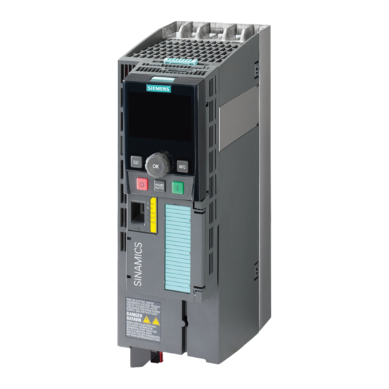
Design of the frequency converter Main components of the inverter Each SINAMICS G120 inverter comprises a Control Unit and a Power Module. • The Control Unit controls and monitors the Power Module and the connected motor. • The Power Modules are available for motors with a power range of between 0.37 kW and... - Page 16 Design of the frequency converter Additional inverter components Accessories are available for the inverter, e.g. reactors, filters and operator panels (Basic Operator Panel BOP-2 or Intelligent Operator Panel IOP). Figure 2-1 Design of the inverter (example) You can find additional information about the inverter accessories in the attached component documentation and in the operating instructions.
-
Page 17: Installing
Installing Installing the Power Module Connecting the Power Module to the motor and line supply Figure 3-1 Connecting the PM340 1AC Power Module Figure 3-2 Connecting the PM230 IP20 and push-through Power Module Figure 3-3 Connecting the PM230 IP55 Power Module Converter with Control Units CU230P-2;... - Page 18 Installing 3.1 Installing the Power Module Figure 3-4 Connecting the PM240, PM240-2 IP20 and push-through Power Module Figure 3-5 Connecting the PM250 Power Module Figure 3-6 Connecting the PM260 Power Module Converter with Control Units CU230P-2; CU240B-2; CU240E-2 Getting Started, 04/2014, A5E32885834B AB...
-
Page 19: Snapping The Control Unit Onto The Power Module
Installing 3.2 Snapping the Control Unit onto the Power Module Figure 3-7 Connecting the PM330 Power Module Snapping the Control Unit onto the Power Module Attaching the CU Removing the CU Attaching the Operator Panel Converter with Control Units CU230P-2; CU240B-2; CU240E-2 Getting Started, 04/2014, A5E32885834B AB... -
Page 20: Installing Control Unit
Installing 3.3 Installing Control Unit Installing Control Unit 3.3.1 CU230P-2 Control Unit 3.3.1.1 Interfaces at the front of the CU230P-2 Interfaces at the front of the Control Unit To access the interfaces at the front of the Control Unit, you must lift the Operator Panel (if one is being used) and open the front doors. -
Page 21: Terminal Strips Of The Cu230P-2
Installing 3.3 Installing Control Unit 3.3.1.2 Terminal strips of the CU230P-2 *) The following applies to systems complying with UL: A maximum of 3 A 30 V DC or 2 A 250 V AC may be connected via terminals 18 / 20 (DO 0 NC) and 23 / 25 (DO 2 NC). ①... -
Page 22: Factory Setting
Installing 3.3 Installing Control Unit Factory setting The factory setting of the terminals depends on whether the Control Unit has a PROFIBUS / PROFINET interface. Factory setting of the terminals for Control Units without Factory setting of the terminals for Control Units with PROFIBUS interface PROFIBUS interface Fieldbus interface is not active. -
Page 23: Cu240B / Cu240E Control Unit
Installing 3.3 Installing Control Unit The factory settings described above for USS and PROFIBUS/PROFINET terminals correspond to default setting 12 (two-wire control using method 1) or default setting 7 (switchover between fieldbus and jog using DI 3). See also: Default settings of the terminal strip (Page 28). 3.3.2 CU240B / CU240E Control Unit 3.3.2.1... -
Page 24: Terminal Strips On Cu240B-2 Control Units
Installing 3.3 Installing Control Unit 3.3.2.2 Terminal strips on CU240B-2 Control Units ① The analog input is supplied from the internal 10 V voltage. ② The analog input is supplied from an external 10 V voltage. ③ Wiring when using the internal power supplies. Connection of a contact switching to P potential. ④... - Page 25 Installing 3.3 Installing Control Unit Factory setting of the CU240B-2 The factory setting of the terminals depends on whether the Control Unit has a PROFIBUS / PROFINET interface. Factory setting of the terminals for Control Units without Factory setting of the terminals for Control Units with PROFIBUS interface PROFIBUS interface Fieldbus interface is not active.
-
Page 26: Terminal Strips On Cu240E-2 Control Units
Installing 3.3 Installing Control Unit 3.3.2.3 Terminal strips on CU240E-2 Control Units ① The analog inputs are supplied from an external 10 V source. ② The analog inputs are supplied from the internal 10 V voltage. ③ Wiring when using the internal power supplies. Connecting a contact switching to P. ④... - Page 27 Installing 3.3 Installing Control Unit Factory setting of the CU240E-2 The factory setting of the terminals depends on whether the Control Unit has a PROFIBUS / PROFINET interface. Factory setting of the terminals for Control Units without Factory setting of the terminals for Control Units with PROFIBUS interface PROFIBUS interface Fieldbus interface is not active.
-
Page 28: Default Settings Of The Terminal Strip
Installing 3.3 Installing Control Unit The factory settings described above for USS and PROFIBUS/PROFINET terminals correspond to default setting 12 (two-wire control using method 1) or default setting 7 (switchover between fieldbus and jog using DI 3). See also: Default settings of the terminal strip (Page 28). 3.3.3 Default settings of the terminal strip Default setting 1: Two fixed speeds... - Page 29 Installing 3.3 Installing Control Unit Default setting 7: Switch over between fieldbus and jogging using DI 3 Default setting 8: Motorized potentiometer (MOP) with safety All Control Units function Selected with Control Units CU240E-2 STARTER: Fieldbus with data set switchover •...
- Page 30 Installing 3.3 Installing Control Unit Default setting 14: Switch over between fieldbus and motorized potentiometer (MOP) using DI 3 Control Units CU230P-2 and CU240E-2 Selected with STARTER: Process industry with fieldbus • BOP-2: Proc Fb • PROFIdrive telegram 20 Fieldbus interface is not active. Default setting 15: Switch over between analog setpoint and motorized potentiometer (MOP) using DI 3 Control Units CU230P-2 and CU240E-2...
- Page 31 Installing 3.3 Installing Control Unit Default setting 17: Two-wire control Default setting 18: Two-wire control Default setting 19: Three-wire control with method 2 with method 3 with method 1 All Control Units All Control Units All Control Units Selected with Selected with Selected with STARTER: 2-wire...
-
Page 32: Wiring The Terminal Strip
See also:EMC installation guideline (http://support.automation.siemens.com/WW/view/en/60612658) 3. Use the shield connection plate of the Control Unit as strain relief, also see:Overview of the shield connection kits (http://support.automation.siemens.com/WW/news/en/67225884). -
Page 33: Connecting Up The Fieldbus
Installing 3.4 Connecting up the fieldbus Connecting up the fieldbus Interfaces at the lower side of the CU230P-2 Control Unit Interfaces at the lower side of the CU240B-2 and CU240E-2 Control Units Converter with Control Units CU230P-2; CU240B-2; CU240E-2 Getting Started, 04/2014, A5E32885834B AB... - Page 34 Installing 3.4 Connecting up the fieldbus Description files for fieldbuses The description files contain the information required to configure and operate the inverter on a fieldbus under a higher-level control. Description file Download Alternative to download GSD for PROFIBUS Internet: GSD and GSDML are saved in the (http://support.automation.sieme inverter.
-
Page 35: Commissioning
5 m. PC tools STARTER STARTER on DVD: Connected to the inverter via USB port, PROFIBUS or 6SL3072-0AA00-0AG0 PROFINET Download: STARTER (http://support.automation.siemens.com/WW/view/en/10804985/ 130000) Startdrive Startdrive on DVD: Connected to the inverter via USB port, PROFIBUS or 6SL3072-4CA02-1XG0 PROFINET Download: Startdrive (http://support.automation.siemens.com/WW/view/en/68034568) -
Page 36: Iop Intelligent Operator Panel
Commissioning 4.2 IOP Intelligent Operator Panel IOP Intelligent Operator Panel The IOP is an operator device with which you can commission the frequency converter locally, enter parameters and monitor operation. The display is subdivided into various areas • Status and diagnostics display •... - Page 37 Commissioning 4.2 IOP Intelligent Operator Panel Menu structure The menu depicted here shows the basic structure. There are different sub-structures, depending on the software version and the Control Unit. Instead of using the application Wizards, you can also use individual parameters to directly change all of the settings.
-
Page 38: Commissioning
(Page 36)". If the IOP does not contain the actual frequency converter software, a message is displayed "Update is required". You can find the required information on the Internet at "http://support.automation.siemens.com/WW/view/de/67273266 (http://support.automation.siemens.com/WW/view/en/67273266)". In the basic commissioning, select the control mode for the motor, enter the motor data and define the pre-assignment of the frequency converter interfaces. -
Page 39: Settings In The Basic Commissioning Menu
Commissioning 4.3 Commissioning 4.3.1 Settings in the basic commissioning menu Basic commissioning The "Basic commissioning" wizard sets the most important data for commissioning the drive. The number of commissioning steps depends on the particular Control Unit. Procedure Proceed as follows to carry out basic commissioning of the inverter: 1. - Page 40 Commissioning 4.3 Commissioning Screen form Setting Param. Overview of the settings Check list + select < Continue > Save settings Save Saving, please wait If the IOP Assistant does not offer this setting, after completing the basic commissioning, set parameter p1900 to a value of 1 using the parameter menu. You have completed the inverter's basic commissioning.
-
Page 41: Enable "Safe Torque Off" Safety Function
Commissioning 4.3 Commissioning Procedure To identify the motor data, proceed as follows: 1. Switch on the motor. You can enter the on command via the terminal strip, fieldbus, or operator panel. 2. Wait until the inverter switches off the motor after completion of the motor data identification. -
Page 42: The Most Important Parameters At A Glance
Commissioning 4.3 Commissioning Procedure To enable the "Safe Torque Off" safety function, proceed as follows: 1. Select: "Basic Safety" commissioning Enter the password for fail-safe function (factory setting = 0) Confirm with When "Password correct" is displayed, acknowledge with "Continue". If you have entered the wrong password, you can return with the button "ESC"... - Page 43 Commissioning 4.3 Commissioning Table 4- 3 Set jogging Parameter Description p1058 Jog 1 p1059 Jog 2 Table 4- 4 Selecting the fieldbus protocol Parameter Possible settings (selection options, depend on the CU type) p2030 0: No protocol (this means: Control via digital inputs/connecting terminals) 1: USS 2: Modbus 3: PROFIBUS DP...
- Page 44 Commissioning 4.3 Commissioning Table 4- 7 Setting the control mode Parameter Possible settings p1300 Setting the open-loop and closed-loop control mode of a drive 0: V/f control with linear characteristic 1: Linear V/f characteristic with Flux Current Control (FCC) 2: V/f control with square-law characteristic 3: Freely selectable V/f characteristic 4: Linear V/f characteristic ECO 5: Linear V/f characteristic for applications requiring a precise frequency in textile systems...
- Page 45 Commissioning 4.3 Commissioning Table 4- 10 Changing the function of a digital input Changing the function Examples Function : Switch on motor via DI 2. 1. Select the required function marked using a "BI" parameter. Setting : p0840 = 722.2 2.
- Page 46 Commissioning 4.3 Commissioning Table 4- 14 Changing the function of an analog input Changing the function Examples Function : AI 0 provides the setpoint for the PID 1. Select the required function marked using a "CI" parameter. controller. 2. Set this parameter to the value of status parameter r0755.x of Setting : p2253 = 55[0] the analog input.
-
Page 47: Manuals And Technical Support
Fieldbus function manual Configuring fieldbuses. for the SINAMICS G110M, G120, G120C and G120D inverters List Manual Graphic function block for SINAMICS G120 inverters with diagrams. the following Control Units: List of all parameters, alarms and faults. CU230P-2 Control Unit •... -
Page 48: Product Support
Great Britain +33 (0) 821 801 122 +49 (0)911 895 7222 +39 (02) 24362000 +34 902 237 238 +44 161 446 5545 Other service telephone numbers: Product support (http://www.siemens.com/automation/service&support) Converter with Control Units CU230P-2; CU240B-2; CU240E-2 Getting Started, 04/2014, A5E32885834B AB...