Siemens Sinamics PM250 Hardware Installation Manual
Hide thumbs
Also See for Sinamics PM250:
- Hardware installation instructions (2 pages) ,
- Hardware installation manual (80 pages) ,
- Hardware installation manual (94 pages)
Table of Contents

Related Manuals for Siemens Sinamics PM250


Summary of Contents for Siemens Sinamics PM250
- Page 3 ___________________ PM250 Power Module Changes in this manual ___________________ Fundamental safety instructions ___________________ SINAMICS Introduction ___________________ Installing/mounting SINAMICS G120 PM250 Power Module ___________________ Connection ___________________ Operation, service and maintenance Hardware Installation Manual ___________________ Technical specifications ___________________ Spare parts and accessories ___________________ Appendix Edition 01/2016...
- Page 4 Note the following: WARNING Siemens products may only be used for the applications described in the catalog and in the relevant technical documentation. If products and components from other manufacturers are used, these must be recommended or approved by Siemens. Proper transport, storage, installation, assembly, commissioning, operation and maintenance are required to ensure that the products operate safely and without any problems.
-
Page 5: Table Of Contents
Table of contents Changes in this manual ........................... 7 Fundamental safety instructions ......................9 General safety instructions ....................... 9 Safety instructions for electromagnetic fields (EMF) .............. 13 Handling electrostatic sensitive devices (ESD) ..............13 Industrial security ........................14 Residual risks of power drive systems ..................15 Introduction ............................ - Page 6 Table of contents Overload capability of the inverter ..................53 Cable cross-sections and tightening torques ................. 55 General data .......................... 56 Power-dependent data ......................58 7.4.1 Current derating depending on the pulse frequency.............. 60 Restrictions for special ambient conditions ................61 Electromagnetic compatibility of the inverter .................
-
Page 7: Changes In This Manual
Changes in this manual Changes with respect to the manual, edition 09/2012 All chapters in the manual have been completely revised. PM250 Power Module Hardware Installation Manual, 01/2016, A5E36265179B-AA... - Page 8 Changes in this manual PM250 Power Module Hardware Installation Manual, 01/2016, A5E36265179B-AA...
-
Page 9: Fundamental Safety Instructions
Fundamental safety instructions General safety instructions DANGER Danger to life due to live parts and other energy sources Death or serious injury can result when live parts are touched. • Only work on electrical devices when you are qualified for this job. •... - Page 10 Fundamental safety instructions 2.1 General safety instructions WARNING Danger to life when live parts are touched on damaged devices Improper handling of devices can cause damage. For damaged devices, hazardous voltages can be present at the enclosure or at exposed components;...
- Page 11 Fundamental safety instructions 2.1 General safety instructions WARNING Danger to life through unexpected movement of machines when using mobile wireless devices or mobile phones Using mobile wireless devices or mobile phones with a transmit power > 1 W closer than approx.
- Page 12 Fundamental safety instructions 2.1 General safety instructions WARNING Danger to life when safety functions are inactive Safety functions that are inactive or that have not been adjusted accordingly can cause operational faults on machines that could lead to serious injury or death. •...
-
Page 13: Safety Instructions For Electromagnetic Fields (Emf)
Fundamental safety instructions 2.2 Safety instructions for electromagnetic fields (EMF) Safety instructions for electromagnetic fields (EMF) WARNING Danger to life from electromagnetic fields Electromagnetic fields (EMF) are generated by the operation of electrical power equipment such as transformers, converters or motors. People with pacemakers or implants are at a special risk in the immediate vicinity of these devices/systems. -
Page 14: Industrial Security
Siemens recommends strongly that you regularly check for product updates. For the secure operation of Siemens products and solutions, it is necessary to take suitable preventive action (e.g. cell protection concept) and integrate each component into a holistic, state-of-the-art industrial security concept. -
Page 15: Residual Risks Of Power Drive Systems
Fundamental safety instructions 2.5 Residual risks of power drive systems Residual risks of power drive systems The control and drive components of a drive system are approved for industrial and commercial use in industrial line supplies. Their use in public line supplies requires a different configuration and/or additional measures. - Page 16 Fundamental safety instructions 2.5 Residual risks of power drive systems 3. Hazardous shock voltages caused by, for example, – Component failure – Influence during electrostatic charging – Induction of voltages in moving motors – Operation and/or environmental conditions outside the specification –...
-
Page 17: Introduction
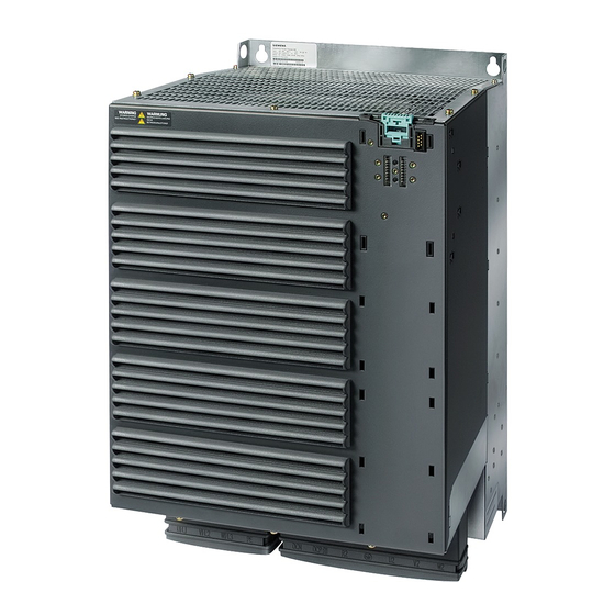
Introduction Overview PM250 Power Modules belong to the modular family of SINAMICS G120 inverters. A G120 inverter comprising Control Unit and Power Module. Dynamic braking with energy recovery into the line supply is characteristic for PM250 Power Modules. PM250 Power Modules are designed for 3 AC 380 V … 480 V. Depending on the power rating, they are supplied in frame sizes FSC …... - Page 18 Introduction Permissible power range of the motors For the Power Modules, induction motors are permissible in the range from 25 % … 150 % of the inverter power without any restrictions. Use motors for inverter operation or with higher insulation levels. PM250 Power Module Hardware Installation Manual, 01/2016, A5E36265179B-AA...
-
Page 19: Installing/Mounting
Inverters for systems in the United States / Canada (UL/cUL) ● For configurations in conformance with UL/cUL, use the UL/cUL-approved fuses, Class J or Siemens 3NE1 semiconductor fuses, which are specified in this manual. If you use semiconductor fuses as branch protection, then you must install them in the same electrical cabinet as the inverter. -
Page 20: Power Losses And Air Cooling Requirements
● Terminal voltage, V = 2000 V ● Suitable for SPD applications, type 1 or type 2 Alternatively, use a surge protection device, article number 5SD7 424-1 from Siemens AG. Power losses and air cooling requirements Cooling requirements Depending on the power loss of the individual components, the control cabinet will require a cooling airflow to prevent the components from overheating. - Page 21 Installing/mounting 4.2 Power losses and air cooling requirements 5. Ensure that the components are provided with adequate cooling air through the cooling openings. 6. Use the appropriate air barriers to prevent cooling air short circuits Image 4-1 Air barriers for avoiding cooling air short circuits PM250 Power Module Hardware Installation Manual, 01/2016, A5E36265179B-AA...
-
Page 22: Mounting The Power Modules
Installing/mounting 4.3 Mounting the Power Modules Mounting the Power Modules 4.3.1 Installing Power Modules Installing Power Modules The following is required to correctly install a Power Module: ● Install the Power Module in a control cabinet. ● Install the Power Module vertically with the line and motor connections facing downwards. ●... -
Page 23: Dimension Drawings And Drilling Dimensions
Installing/mounting 4.3 Mounting the Power Modules 4.3.2 Dimension drawings and drilling dimensions The following dimensioned drawings and drilling patterns are not to scale. Table 4- 1 Mounting dimensions Frame size Width (mm) Height (mm) Depth (mm) with shield connec- tion kit FSC without/with filter FSD without filter FSD with filter... - Page 24 Installing/mounting 4.3 Mounting the Power Modules Depth with Control Unit and Operator Panel (mm) CU230P-2 CU240B/E-2 CU250S-2 + 59 + 41 + 62 with Control Unit: • + 70 + 52 + 73 With Control Unit and blanking cover / BOP-2: •...
-
Page 25: Control Unit Installation
Installing/mounting 4.4 Control Unit installation Control Unit installation Plug the Control Unit onto the Power Module as shown in the diagram. By plugging on the Control Unit, you also establish all of the electrical connections between the Control Unit and the Power Module. - Page 26 Installing/mounting 4.5 Installing supplementary components PM250 Power Module Hardware Installation Manual, 01/2016, A5E36265179B-AA...
-
Page 27: Connection
To protect against indirectly touching part of the motor circuit of an inverter and to automatically shut down in the case of a fault according to DIN EN 60364-4-41 (VDE 0100- 410). (http://support.automation.siemens.com/WW/view/en/103474630) PM250 Power Module Hardware Installation Manual, 01/2016, A5E36265179B-AA... - Page 28 The equipment must satisfy the following properties and general conditions: – super-resistant RCD/RCM type B, with a trip current of 300 mA. e.g. a SIQUENCE circuit breaker from Siemens. – Only one inverter is supplied from each RCD/RCM – The motor cables are shielded and are not longer than 50 m. You can find additional...
-
Page 29: Line And Motor Connection
Connection 5.1 Line and motor connection Line and motor connection Note: Arrangement of the line and motor terminals (Page 36). EMC-compliant installation (Page 38). The machine manufacturer must ensure that in operation the voltage drop between the transformer input terminals and the inverter when operated with its rated values is less than 5.1.1 Permissible line supplies Note... - Page 30 Connection 5.1 Line and motor connection TN line system A TN line system transfers the PE protective conductor to the installed plant or system using a cable. Generally, in a TN line system the neutral point is grounded. There are versions of a TN line supply with a grounded line the conductor, e.g.
- Page 31 Connection 5.1 Line and motor connection TT line system In a TT line system, the transformer grounding and the installation grounding are independent of one another. There are TT line supplies where the neutral conductor N is either transferred – or not. Inverter operated on a TT line system ●...
-
Page 32: Dimensioning The Protective Conductor
Connection 5.1 Line and motor connection IT system In an IT line system, all of the conductors are insulated with respect to the PE protective conductor – or connected to the PE protective conductor through an impedance. There are IT line supplies where the neutral conductor N is either transferred – or not. Inverter operated on an IT line system ●... - Page 33 Connection 5.1 Line and motor connection Laying the protective conductor ① For the protective conductor of the line-system connection within a machine or system, the follow- ing applies: 1. Observe the local regulations for protective conductors subject to an increased leakage cur- rent at the site of operation.
-
Page 34: Connection Overview
Connection 5.1 Line and motor connection 5.1.3 Connection overview Note Line filter The inverters are available with or without integrated line filter (Class A). There are external filters (Class B) for increased EMC requirements for frame size FSC. See Line filter (Page 71) 5.1.4 Length of motor cable... -
Page 35: Motor Connection
Unshielded cable FSD … FSF 5.1.5 Motor connection Star and delta connection Siemens motors have a diagram inside the terminal box showing both connection meth- ods: • Star connection (Y) • Delta connection (Δ) The motor rating plate provides data about the correct connection. -
Page 36: Inverter Terminals
Connection 5.1 Line and motor connection 5.1.6 Inverter terminals Table 5- 3 Connection type, cable cross sections and tightening torques Inverters Connection Cross-section and tightening torque Strip lengths Metric Imperial Line cable, motor cable Terminal 4 …10 mm: 2.3 Nm 12 …... - Page 37 Connection 5.1 Line and motor connection Establishing the line and motor connection, frame sizes FSD … FSF The terminals for the line and motor connection have covers to provide touch protection. 1. To connect up, release the catches on both sides of the terminal covers using a screwdriver 2.
-
Page 38: Emc-Compliant Installation
Connection 5.2 EMC-compliant installation EMC-compliant installation 5.2.1 Avoiding electromagnetic interference Only the concurrent use of filtering, grounding and shielding ensure an installation in accordance with the EMC requirements. The next sections cover all of the most important rules for the installation of inverter and drive systems. - Page 39 Connection 5.2 EMC-compliant installation ● Equip the following components with interference suppression elements: – Coils of contactors – Relays – Solenoid valves – Motor holding brakes Interference suppression elements include RC elements or varistors for AC-operated coils and freewheeling diodes for DC-operated coils. Connect the interference suppression element directly at the coil.
- Page 40 ● Only use metallic or metallized connectors for the plug connections for shielded data cables (e.g. PROFIBUS connection). Further information You can find additional information about the EMC installation guidelines under (https://support.industry.siemens.com/cs/ww/de/view/60612658/en): PM250 Power Module Hardware Installation Manual, 01/2016, A5E36265179B-AA...
-
Page 41: Installing The Converter In Compliance With Emc Rules
Connection 5.2 EMC-compliant installation 5.2.3 Installing the converter in compliance with EMC rules Rules for cable installation to ensure EMC ● Install the inverter on a metal mounting plate. The mounting plate must be unpainted and highly electrically conductive. ● Use shielded cables for the following connections: –... -
Page 42: Emc-Compliant Cabinet Design
Connection 5.2 EMC-compliant installation 5.2.4 EMC-compliant cabinet design The most cost-effective method of implementing interference suppression measures within the control cabinet is to ensure that interference sources and interference sinks are spatially separated. EMC zone concept within the control cabinet Split up the complete control cabinet into EMC zones. -
Page 43: Equipotential Bonding
Connection 5.2 EMC-compliant installation 5.2.5 Equipotential bonding Grounding measures Proceed as follows to ground the drive system: ● For several cabinets, install a common PE bar for all cabinet elements ● Connect all of the drive system components to the PE conductor ●... - Page 44 Connection 5.2 EMC-compliant installation Diagrams for grounding and high-frequency equipotential bonding measures The following diagram illustrates all grounding and high-frequency equipotential bonding measures using the example of a cabinet with a SINAMICS G120. Grounding measures ① Conventional grounding without any special HF properties High-frequency equipotential bonding measures ②...
- Page 45 The following diagram shows the additional measures for high-frequency equipotential bonding Image 5-6 Additional measures for high frequency equipotential bonding of the drive system Further information You can find additional information about the EMC installation guidelines at (https://support.industry.siemens.com/cs/ww/de/view/60612658/en): PM250 Power Module Hardware Installation Manual, 01/2016, A5E36265179B-AA...
- Page 46 Connection 5.2 EMC-compliant installation PM250 Power Module Hardware Installation Manual, 01/2016, A5E36265179B-AA...
-
Page 47: Operation, Service And Maintenance
WARNING Danger due to incorrect repair Repairs may only be carried out by Siemens Service, by repair centers authorized by Siemens or by authorized personnel who are thoroughly acquainted with all the warnings and operating procedures contained in this manual. -
Page 48: Maintenance
Note The actual maintenance intervals depend on the installation and operating conditions. Siemens offers its customers support in the form of service contracts. For further information, contact your Siemens regional office or sales office. PM250 Power Module... -
Page 49: Replacing Fans
Operation, service and maintenance 6.3 Replacing fans Replacing fans Service life of the fan The average service life of the fan is 40,000 hours. In practice, however, the service life may deviate from this value. Especially a dusty environment can block up the fan. The fan must be replaced in good time to ensure that the inverter is ready for operation. - Page 50 Operation, service and maintenance 6.3 Replacing fans Fan replacement, frame sizes FSD and FSE: Procedure 1. Switch the inverter off. 2. Disconnect all the cables from the Power Module. ⑤ 3. Release the fan cover catches ② ③ 4. Release and remove the fan cover ③...
- Page 51 Operation, service and maintenance 6.3 Replacing fans Fan replacement, frame size FSF Procedure 1. Switch-off the inverter. 2. Disconnect all the cables from the Power Module. ① ② 3. Release the four screws and remove the fan cover plate ③ 4.
- Page 52 Operation, service and maintenance 6.3 Replacing fans PM250 Power Module Hardware Installation Manual, 01/2016, A5E36265179B-AA...
-
Page 53: Technical Specifications
The power loss values specified are typical values. You will find further information on the Internet at: Power loss data for partial load operation (https://support.industry.siemens.com/cs/ww/en/view/94059311) Overload capability of the inverter Overload capability is the property of the inverter to temporarily supply a current that is higher than the rated current to accelerate a load. - Page 54 Technical specifications 7.1 Overload capability of the inverter Load cycles and typical applications: "Low Overload" load cycle "High Overload" load cycle The "Low Overload" load cycle assumes a The "High Overload" load cycle permits, for uniform base load with low requirements reduced base load, dynamic accelerating placed on brief accelerating p phases.
-
Page 55: Cable Cross-Sections And Tightening Torques
Technical specifications 7.2 Cable cross-sections and tightening torques Cable cross-sections and tightening torques Table 7- 1 Connection type, cable cross sections and tightening torques Inverters Connection Cross-section and tightening torque Strip lengths Metric Imperial Line cable, motor cable Terminal 4 …10 mm : 2.3 Nm 12 …... -
Page 56: General Data
Technical specifications 7.3 General data General data Property Version Line voltage 3-phase 380 … 480 VAC ± 10% Output voltage 3-phase 0 VAC … input voltage x 0.87 (max.) Input frequency 50 Hz … 60 Hz, ± 3 Hz Output frequency 0 …... - Page 57 Technical specifications 7.3 General data Property Version Climatic environmental Better than 3K3 according to EN 60721-3-3 conditions Temperature range without derating • – LO base load power 0 °C … +40 °C – HO base load power: 0° C … +50° C Temperature range with derating •...
-
Page 58: Power-Dependent Data
Technical specifications 7.4 Power-dependent data Power-dependent data Note The values for Low Overload (LO) are identical with those of the rated values. Table 7- 2 PM250, IP20, frame sizes C, 3 AC 380 V … 480 V Article No. - with filter 6SL3225-…... - Page 59 Technical specifications 7.4 Power-dependent data Table 7- 4 PM250, IP20, frame sizes E, 3 AC 380 V … 480 V Article No. - with filter 6SL3225-… 0BE33-0AA0 0BE33-7AA0 LO base load power 37 kW 45 kW LO base load input current 70 A 84 A LO base load output current...
-
Page 60: Current Derating Depending On The Pulse Frequency
Technical specifications 7.4 Power-dependent data 7.4.1 Current derating depending on the pulse frequency Article number LO base LO baseload output current [A] at a pulse frequency of… load 6SL3225-… 4 kHz 6 kHz 8 kHz 10 kHz 12 kHz 14 kHz 16 kHz power -0BE25-5AA0... -
Page 61: Restrictions For Special Ambient Conditions
Technical specifications 7.5 Restrictions for special ambient conditions Restrictions for special ambient conditions Maximum current at low speeds NOTICE Negative impact on the inverter service life. At low speeds, the inverter can only briefly supply the base load output current. It is especially important to note that DC voltage operation (continuous operation at 0 Hz) is not permissible. - Page 62 Technical specifications 7.5 Restrictions for special ambient conditions The Control Unit and operator panel can restrict the maximum permissible operating ambient temperature of the Power Module. Current derating or temperature reduction depending on the installation altitude Above 1000 m above sea level you must reduce the inverter output current or the permissible operating ambient temperature as a result of the lower cooling capability of the air.
-
Page 63: Electromagnetic Compatibility Of The Inverter
Technical specifications 7.6 Electromagnetic compatibility of the inverter Electromagnetic compatibility of the inverter The electromagnetic compatibility refers to both the immunity and the emitted interference of a device. The following disturbance variables must be taken into consideration when evaluating the electromagnetic compatibility: ●... -
Page 64: Assigning The Inverter To Emc Categories
The inverters have been tested in accordance with the EMC product standard EN 61800-3. The declaration of conformity is available at Hotspot-Text (http://support.automation.siemens.com/WW/view/en/58275445) Requirements for electromagnetic compatibility To comply with the requirements of EN 61800-3, all drives must be installed in accordance with the manufacturer's instructions and EMC directives. - Page 65 Technical specifications 7.6 Electromagnetic compatibility of the inverter Second environment - category C4 The unfiltered inverters correspond to category C4. EMC measures in the second environment, category C4, are carried out on the basis of an EMC plan on the system level. Further information: EMC-compliant installation (Page 38).
-
Page 66: Harmonics
Technical specifications 7.6 Electromagnetic compatibility of the inverter First environment - category C2 Immunity With respect to their immunity, the inverters are suitable for the first environment, Category Emitted interference ● Low-frequency, cable-conducted interference voltages (harmonics) Your line supply defines as to whether the inverter can satisfy the requirements of the first environment, Category C2. -
Page 67: Emc Limit Values In South Korea
Please note that the final statement on compliance with the standard is given by the respective label attached to the individual unit. You can find the Configuration Manual "EMC installation guidelines" under (http://support.automation.siemens.com/WW/view/en/60612658) PM250 Power Module Hardware Installation Manual, 01/2016, A5E36265179B-AA... - Page 68 Technical specifications 7.6 Electromagnetic compatibility of the inverter PM250 Power Module Hardware Installation Manual, 01/2016, A5E36265179B-AA...
-
Page 69: Spare Parts And Accessories
Spare parts and accessories Spare parts 6SL3200-0SF03-0AA0 fan kit For FSC Power Modules: ● 6SL3225-0BE25-5AA0 (7.5 kW) ● 6SL3225-0BE27-5AA0 (11 kW) ● 6SL3225-0BE31-1AA0 (15 kW) 6SL3200-0SF04-0AA0 fan kit For FSD Power Modules: ● 6SL3225-0BE31-5AA0 (18.5 kW) ● 6SL3225-0BE31-8AA0 (22 kW) For FSE Power Modules: ●... -
Page 70: Optional Accessories
Spare parts and accessories 8.2 Optional accessories Repair and wearing parts and/or consumables You can find additional information about repair and wearing parts or consumables that can be ordered here (https://www.automation.siemens.com/sow?sap-language=EN) Optional accessories Which components are available? ● Line filter ●... -
Page 71: Line Filter
Spare parts and accessories 8.2 Optional accessories 8.2.2 Line filter With a line filter, the inverter can achieve a higher radio interference class. The line filters integrated in the inverter correspond to Class A according to EN55011. The filters are available for radio interference suppression class A or B according to EN55011. - Page 72 Spare parts and accessories 8.2 Optional accessories Image 8-3 FSF dimensions Image 8-4 Mounting position FSF Table 8- 1 Dimensions and weights Article number Overall dimensions Drilling dimensions Mounting Weight (mm) (mm) (kg) Screws/torque (Nm) 6SL3203-0BD23-8SA0 4 x M5 / 3.0 6SL3203-0BE32-5AA0 4 x M8 / 13 12.4...
- Page 73 Spare parts and accessories 8.2 Optional accessories Technical specifications and assignment tables Table 8- 2 Technical specifications Article number Power loss Connection (mm Degree (W) at 50 Hz of pro- Line / PE Power Module tection 6SL3203-0BD23-8SA0 7.5 … 15 4 mm screw terminals Integrated, 400 mm...
-
Page 74: Output Reactor
Spare parts and accessories 8.2 Optional accessories 8.2.3 Output reactor Mounting position Clearances to other devices Keep shaded areas free of any devices and components. Image 8-5 Minimum clearances of the output reactor to other devices, space-saving mounting examples If you use an output reactor, then it is not permissible that the output frequency exceeds 150 Hz. - Page 75 Spare parts and accessories 8.2 Optional accessories Dimensions and drilling patterns Image 8-6 Output reactor as base component for frame size FSC Image 8-7 Standalone output reactor for frame sizes FSD … FSF PM250 Power Module Hardware Installation Manual, 01/2016, A5E36265179B-AA...
- Page 76 Spare parts and accessories 8.2 Optional accessories Table 8- 4 Dimensions and weights Article number Overall dimensions Drilling dimensions Tightening Weigh (mm) (mm) screws/torque t (kg) (Nm) Reactor that can be mounted under the unit 6SL3202-0AJ23-2CA0 4 x M5 / 3.0 Reactor that cannot be mounted under the unit 6SE6400-3TC05-4DD0 70.5...
- Page 77 Spare parts and accessories 8.2 Optional accessories Table 8- 6 Assignment table Output reactor Power Module Article number Article number Frame size 6SL3202-0AJ23-2CA0 6SL3225-0BE25-5☐A0 6SL3225-0BE27-5☐A0 6SL3225-0BE31-1☐A0 6SE6400-3TC05-4DD0 6SL3225-0BE31-5☐A0 6SE6400-3TC03-8DD0 6SL3225-0BE31-8☐A0 6SE6400-3TC05-4DD0 6SL3225-0BE32-2☐A0 6SE6400-3TC08-0ED0 6SL3225-0BE33-0☐A0 6SE6400-3TC07-5ED0 6SL3225-0BE33-7☐A0 6SE6400-3TC14-5FD0 6SL3225-0BE34-5☐A0 6SE6400-3TC15-4FD0 6SL3225-0BE35-5☐A0 6SE6400-3TC14-5FD0 6SL3225-0BE37-5☐A0 PM250 Power Module...
-
Page 78: Sine-Wave Filter
Spare parts and accessories 8.2 Optional accessories 8.2.4 Sine-wave filter The sine-wave filter at the inverter output limits the voltage rate-of-rise and the peak voltages at the motor winding. The maximum permissible length of motor feeder cables is increased to 300 m. The following applies when using a sine-wave filter: ●... - Page 79 Spare parts and accessories 8.2 Optional accessories Image 8-10 Dimensions - standalone filter Image 8-11 Mounting position - standalone filter Table 8- 7 Dimensions and weights Sine-wave filter Overall dimensions Drilling dimensions Tightening Weight (mm) (mm) screws/torque (kg) (Nm) Footprint filter 6SL3202-0AE22-0SA0 4 x M5 / 3.0 6SL3202-0AE23-3SA0...
- Page 80 Spare parts and accessories 8.2 Optional accessories Technical specifications and assignment tables Table 8- 8 Technical specifications Article number Connection (mm Degree dU/dt limit Power [V/ms] loss [W] Motor / PE Power Module protec- at 50 Hz tion 6SL3202-0AE22-0SA0 10 mm² screw Integrated, 500 mm IP20 ≤...
-
Page 81: Connecting A Motor Holding Brake
Spare parts and accessories 8.2 Optional accessories 8.2.5 Connecting a motor holding brake The inverter uses the Brake Relay to control the motor holding brake. Two types of Brake Relay exist: ● The Brake Relay controls the motor holding brake ●... -
Page 82: Mounting And Connecting The Brake Relay
Spare parts and accessories 8.2 Optional accessories 8.2.5.1 Mounting and connecting the brake relay The Brake Relay must be connected to the protective conductor if the motor brake is supplied from a PELV circuit. 8.2.5.2 Mounting and connecting the brake relay The Brake Relay must be connected to the protective conductor if the motor brake is supplied from a PELV circuit. -
Page 83: Technical Data Of The Brake Relay
Spare parts and accessories 8.2 Optional accessories 8.2.5.3 Technical data of the brake relay? Brake Relay Safe Brake Relay 6SL32520BB000AA0 6SL32520BB010AA0 Input voltage via the Power Module 20.4 ... 28.8 VDC Input current via the Power Module Max. 2.5 A Max. -
Page 84: Shield Connection Kit
The shield connection kit is used to connect the shield of the control and motor cable in an EMC-compliant fashion. The instructions for installing the shield connection kit are available in the Internet at (https://support.industry.siemens.com/cs/ww/de/view/23621093/en): Article numbers of the shield connection kit for the different Power Modules ● FSC: 6SL3262-1AC00-0DA0 ●... -
Page 85: Appendix
9.1.1 Overview of the manuals Manuals with additional information that can be downloaded: EMC-compliant electrical cabinet design ● PM250 Hardware Installation Manual (https://support.industry.siemens.com/cs/ww/de/view/64875934/en) Installing Power Modules, reactors and filters. Technical specifications, maintenance (this manual) ● CU230P-2 Compact Operating Instructions (https://support.industry.siemens.com/cs/ww/en/view/109477360) Commissioning the inverter. - Page 86 Appendix 9.1 Manuals and technical support ● CU230P-2 List Manual (https://support.industry.siemens.com/cs/ww/en/view/109477248) Parameter list, alarms and faults. Graphic function diagrams ● CU240B/E-2 List Manual (https://support.industry.siemens.com/cs/ww/en/view/109477251) Parameter list, alarms and faults. Graphic function diagrams ● CU250S-2 List Manual (https://support.industry.siemens.com/cs/ww/en/view/109477253) Parameter list, alarms and faults. Graphic function diagrams ●...
- Page 87 9.1 Manuals and technical support Configuring a manual Further information about the configurability of manuals is available in the Internet: MyDocumentationManager (https://www.industry.siemens.com/topics/global/en/planning- efficiency/documentation/Pages/default.aspx). Select "Display and configure" and add the manual to your "mySupport-documentation": Not all manuals can be configured.
-
Page 88: Configuring Support
Catalog Ordering data and technical information for SINAMICS G inverters. Catalog D31 for download or online catalog (Industry Mall): Everything about SINAMICS G120 (www.siemens.en/sinamics-g120) SIZER The configuration tool for SINAMICS, MICROMASTER and DYNAVERT T drives, motor starters, as well as SINUMERIK, SIMOTION controllers and SIMATIC technology... -
Page 89: Product Support
Disposal Protecting the environment and preserving its resources are corporate goals of the highest priority for Siemens. Our worldwide environmental management system according to ISO 14001 ensures compliance with legislation and sets high standards in this regard. Environmentally friendly design, technical safety and health protection are always firm goals, even at the product development stage. -
Page 90: Standards
EN 61800-3 "EMC Product Standard for Power Drive Systems". ISO 9001 Siemens AG uses a quality management system that meets the requirements of ISO 9001. Underwriters Laboratories The DEVICE is LISTED by UL and CUL for POWER CONVERSION in an environment with the pollution degree 2. -
Page 91: Abbreviations
Appendix 9.4 Abbreviations RCM (Australia) Inverters, frame sizes FSD … FSF with integrated filter satisfy the EMC requirements for Australia. Abbreviations Abbreviation State Alternating current Communauté Européenne Control Unit Direct current Digital input DIP switch Digital output Equivalent circuit diagram European Economic Community ELCB Earth leakage circuit breaker... - Page 92 Appendix 9.4 Abbreviations PM250 Power Module Hardware Installation Manual, 01/2016, A5E36265179B-AA...
-
Page 93: Index
Index Drilling pattern, 75 Accessories, 85 Electrical installation, 27 Air barrier, 21 EMC, 42 EMC installation guideline, 85 Base components, 70 Base load, 53 First environment, 63 Base load input current, 53 Base load output current, 53 Base load power, 53 Getting Started, 85 Brake Relay, 81 Hardware Installation Manual, 85... - Page 94 Index Line reactor Second environment, 63 Dimension drawings, 75 Service life of the fan, 49 Line supply type, 29 Sine-wave filter, 78 Low Overload, 54 SIZER, 88 Standards EN 61800-3, 63, 64 Maintenance EN 61800-3, 63, 64 Cleaning, 48 Star/delta connection, 35 Dirt, 48 Support, 89 Pollution, 48...