Table of Contents
© ELECTROLUX ITALIA S.p.A.
Spares Operations Europe
Corso Lino Zanussi, 30
I - 33080 PORCIA /PN (ITALY)
Fax +39 0434 394096
Edition: 07-2010- Rev.02
Publication no.
599 70 99-00
EN
SERVICE MANUAL
WASHING
Washing machines
&
Washer-dryers
Guide to diagnostics
of electronic controls
ENV06
EWM25xx
EWM35xx
Table of Contents

Related Manuals for Electrolux EWM25 series


Summary of Contents for Electrolux EWM25 series
-
Page 1: Service Manual
SERVICE MANUAL WASHING Washing machines & © ELECTROLUX ITALIA S.p.A. Washer-dryers Publication no. Spares Operations Europe Corso Lino Zanussi, 30 Guide to diagnostics I - 33080 PORCIA /PN (ITALY) 599 70 99-00 of electronic controls Fax +39 0434 394096 ENV06... - Page 2 2/121 07-2010 SOI/DT-mdm FCPD-dp Quality-fz 599 70 99-00...
-
Page 3: Table Of Contents
Content INTRODUCTION..........................6 Purpose of this manual ........................6 Procedure............................6 EWM25xx APPLIANCES CONTROL PANELS ..................7 EWM35xx APPLIANCES CONTROL PANELS ..................8 DIAGNOSTIC SYSTEM........................9 ACCESS TO THE DIAGNOSTIC CYCLE ..................9 Exiting diagnostics mode ....................... 9 PHASES OF THE DIAGNOSTIC CYCLE..................10 ALARMS ............................ - Page 4 E69: Washing heating element interrupted (version WM)..............78 E69: Washing heating element interrupted (version WD) ..............79 E71: NTC washing sensor faulty ..................... 80 E72: Drying NTC sensor on condenser faulty .................. 81 E73: NTC sensor on drying duct faulty .................... 82 E74: NTC sensor wrongly positioned....................
- Page 5 5/121 07-2010 SOI/DT-mdm FCPD-dp Quality-fz 599 70 99-00...
-
Page 6: Introduction
1 INTRODUCTION 1.1 Purpose of this manual The purpose of this Service Manual is to provide a simple and clear description of the procedure to be followed by service engineers when confronted by problems identified by the various alarm codes generated by appliances with the ENV06 electronic control system version EWM25xx and EWM35xx. -
Page 7: Ewm25Xx Appliances Control Panels
2 EWM25xx APPLIANCES CONTROL PANELS ICON ICON AF3- A4.2 AI3&ZI3 Continued 7/121 07-2010 SOI/DT-mdm FCPD-dp Quality-fz 599 70 99-00... -
Page 8: Ewm35Xx Appliances Control Panels
Continued Serie 6 SPECIA Serie 6 Serie 7 3 EWM35xx APPLIANCES CONTROL PANELS These are the available stylings at the moment in this Service Manual, in future some others could be developed. ICON Serie 8 CLUB DISPLAY 8/121 07-2010 SOI/DT-mdm FCPD-dp Quality-fz 599 70 99-00... -
Page 9: Diagnostic System
4 DIAGNOSTIC SYSTEM 4.1 ACCESS TO THE DIAGNOSTIC CYCLE All versions 1. Switch off the appliance. 2. Press and hold down the START/PAUSE button and the nearest OPTION button simultaneously (as represented in figure). 3. Holding down both buttons, switch the appliance on by turning the programme selector one position clockwise. -
Page 10: Phases Of The Diagnostic Cycle
4.3 PHASES OF THE DIAGNOSTIC CYCLE Irrespective of the type of PCB and the configuration of the programme selector it is possible, after entering diagnostic mode, turning the programme selector clockwise or pushing the buttons P1 or P2 (INPUT version), to perform diagnostics on the operation of the various components and to read the alarms. All the alarms are enabled during the diagnostic cycle. - Page 11 INPUT - Reading/Cancellation of the ----- ---- last alarm (*) In most cases, this time is sufficient to check the heating. However, the time can be increased by repeating the phase without draining the water: pass for a moment to a different phase of the diagnostic cycle and then back to the heating control phase (if the temperature is higher than 80°C, heating does not take place).
-
Page 12: Alarms
5 ALARMS Displaying the alarms to the user The alarms displayed to the user are listed below: Door open Drain difficulty (dirty filter) Water fill difficulty (closet tap) AEG Version The alarms are represented through the flashing of the yellow LED, which is above the START-PAUSE button, and can be solved directly by the end user;... -
Page 13: Reading The Alarm Codes
5.2 Reading the alarm codes It is possible to display the last three memorised alarms in the FLASH memory of the electronic board: • Enter diagnostic mode (par. 4.1) • Irrespective of the type of PCB and configuration: turn the programme selector clockwise (version with knob) pushing button P1 (version INPUT) to the tenth position. -
Page 14: Alarm Displaying
5.2.1 Alarm displaying AEG Version: The alarm is displayed by a repeated flashing sequence of the LED placed above the button START / PAUSE with yellow and red light (0.5 seconds on, 0.5 seconds off with a 2.5 second pause between the sequences). •... -
Page 15: Operation Of Alarms During Diagnostics
Button/LED - START / PAUSE Button/LED - START / PAUSE red/yellow light red/green light On/Off Time On/Off Time ON/OFF Value ON/OFF Value (Ver. AEG) (Sec.) (Ver. AEG) (Sec.) Pause Pause 5.2.3 Operation of alarms during diagnostics All alarms are enabled during the components diagnostic phase. 15/121 07-2010 SOI/DT-mdm FCPD-dp Quality-fz 599 70 99-00... -
Page 16: Rapid Reading Of Alarm Codes
Rapid reading of alarm codes The last three alarm codes can be displayed even if the programme selector is not in the tenth position (diagnostics) or if the appliance is in normal operating mode (e.g. during the execution of the washing programme): →... -
Page 17: Table Of Alarms
5.5 TABLE OF ALARMS Alarm Possible fault Action/machine status Reset Alarm Page No alarm ---------------- ---------------- ---------------- ---------- Tap closed or water pressure too low; Drain tube improperly Difficulties in water fill for washing positioned; Water fill solenoid valve is faulty; Leaks from water circuit Cycle is paused with door locked START/RESET on pressure switch;... - Page 18 Alarm Possible fault Action/machine status Reset Alarm Page Heating elem. relay sensing faulty (input signal to microprocessor PCB faulty. Cycle blocked with door closed RESET always 0V or 5V) Door open (after 15 sec.) Door interlock faulty; wiring faulty; PCB faulty. Cycle paused START/RESET 44-46 Problems of door closure...
- Page 19 Alarm Possible fault Action/machine status Reset Alarm Page Heating element power relay faulty Safety drain cycle – Cycle stopped with (incongruence between sensing and PCB faulty. RESET 74-75 door open relay) Current dispersion to earth (value of mains voltage different from main Current dispersion between between heating element and earth.
- Page 20 Alarm Possible fault Action/machine status Reset Alarm Page OFF/ON Machine configuration error Display board. ---------------- RESET OFF/ON Clock faulty Display board. ---------------- RESET Communication error between PCB Wiring between PCB and Inverter faulty; PCB faulty; Inverter faulty. Cycle interrupted OFF/ON and remote devices ON/OFF Drum positioning (DSP) faulty...
- Page 21 Alarm Possible fault Action/machine status Reset Alarm Page Frequency power of appliance out Power supply problems (incorrect / disturbance); PCB faulty. Wait for frequency nominal conditions OFF/ON of limits Voltage too high Power supply problems (incorrect / disturbance); PCB faulty. Wait for frequency nominal conditions OFF/ON Voltage too low...
-
Page 22: Notes Concerning Certain Alarm Codes
5.6 Notes concerning certain alarm codes Configuration alarms E93: If this alarm is generated (when the appliance is switched on), operation of the appliance is blocked, the LEDs placed above or inside the START/PAUSE button start to flash displaying the complete codification (family plus alarm), the display shows the alarm code on condition that the configuration part of the display is ok. -
Page 23: The Diagnostic Programme Cannot Be Accessed
6 THE DIAGNOSTIC PROGRAMME CANNOT BE ACCESSED All LEDs on the circuit board are switched off 6.1.1 Replace or repair the power cable, check the No → Are the power cable and connection OK? connector. Yes ↓ No → Does the suppressor function correctly? Replace the suppressor. -
Page 24: Troubleshooting According To Alarm Codes
7 TROUBLESHOOTING ACCORDING TO ALARM CODES E11: Difficulty in filling water during washing phase Maximum water fill time for each pressure switch level (this time is reset to zero each time the level is reached) Checks to perform: Check that all the connectors are inserted correctly Access the diagnostic cycle and duct water through all the compartments (phases 2,3,4,5) Is water ducted through all the compartments? Is the drain hose positioned... - Page 25 Fig. 1 3500÷4500 Ω Fig.2 Circuit board 3500÷4500 Ω 3500÷4500 Ω 3500÷4500 Ω Fig.3 If there are traces of burning on the circuit board, refer to pages 119-120 Fig.4 25/121 07-2010 SOI/DT-mdm FCPD-dp Quality-fz 599 70 99-00...
-
Page 26: E12: Difficulty In Filling Water During Drying Phase
E12: Difficulty in filling water during drying phase To check if the condensation valve is working, machine measures the increasing water level at the beginning of the drying phase. (Alarm appears after 10 min. of filling without reaching the level). Checks to perform: Check that all the connectors are inserted correctly Start the diagnostic cycle and... - Page 27 3500÷4500 Ω 3500÷4000 Ω Scheda Elettronica 3500÷4500 Ω Fig.26 Fig. 27 Fig. 26 Little hose which connects the condenser to the detergent compartment. If there are traces of burning on the circuit board, refer to pages 119-120 27/121 07-2010 SOI/DT-mdm FCPD-dp Quality-fz 599 70 99-00...
-
Page 28: E13: Water Leakage
E13: Water leakage Overall maximum water fill time exceeded (the sum of all the water fills between one drain phase and the next, to avoid exceeding the maximum volume). Checks to perform: Check that all the connectors are inserted correctly Warning!!!!! This alarm could appear during a normal washing cycle with towels. - Page 29 Fig. 1 3500÷4500 Ω Fig.2 Circuit board 3500÷4500 Ω 3500÷4500 Ω 3500÷4500 Ω Fig.3 If there are traces of burning on the Fig.4 circuit board, refer to page 119-120 29/121 07-2010 SOI/DT-mdm FCPD-dp Quality-fz 599 70 99-00...
-
Page 30: E21: Difficulty In Draining
E21: Difficulty in draining Maximum drain time exceeded (measured for each phase of the cycle) Checks to perform: Check that all the connectors are inserted correctly Clean the filter and restart the diagnostic cycle Is the drain filter clean? to check for further alarms. Is the drain system OK? (drain hose and Disconnect and check the drain system. - Page 31 Fig. 1 Fig.4 Circuit board 155÷200Ω Fig. 5 155÷200Ω 31/121 07-2010 SOI/DT-mdm FCPD-dp Quality-fz 599 70 99-00...
-
Page 32: E21: Difficulty In Draining (With Aqua Control Device)
E21: Difficulty in draining (with Aqua Control device) Maximum drain time exceeded (measured for each phase of the cycle) Checks to perform: Check that all the connectors are inserted correctly Clean the filter and restart the diagnostic cycle Is the drain filter clean? to check for further alarms. - Page 33 E21 (with Aqua Control device) Fig. 1 Fig.4 Fig. 5 Circuit board 155÷200Ω 155÷200Ω 33/121 07-2010 SOI/DT-mdm FCPD-dp Quality-fz 599 70 99-00...
-
Page 34: E22: Difficulty In Draining Water During Drying Phase
E22: Difficulty in draining water during drying phase Checks to perform: Check that all the connectors are inserted correctly Clean the condenser and Is the condenser clean? restart the diagnostic cycle to – (see fig. 24) – check for further alarms. Clean the filter and restart the diagnostic cycle Is the drain filter clean? to check for further alarms. - Page 35 Fig. 1 Fig. 4 Fig. 5 155÷200Ω 155÷20 Fig. 24 Condenser 35/121 07-2010 SOI/DT-mdm FCPD-dp Quality-fz 599 70 99-00...
-
Page 36: E22: Difficulty In Draining Water During Drying Phase (With Aqua Control Device)
E22: Difficulty in draining water during drying phase (with Aqua Control device) Checks to perform: Check that all the connectors are inserted correctly Clean the condenser and Is the condenser clean? restart the diagnostic cycle to – (see fig. 24) – check for further alarms. - Page 37 E22 (with Aqua Control device) Fig. 1 Fig.4 Fig. 5 155÷200Ω 155÷200Ω 155÷20 Fig. 24 Condenser 37/121 07-2010 SOI/DT-mdm FCPD-dp Quality-fz 599 70 99-00...
-
Page 38: E23: Malfunction Of The Component (Triac) That Controls The Drain Pump
E23: Malfunction of the component (triac) that controls the drain pump Checks to perform: Check that all the connectors are inserted correctly Is the resistance of the pump Is the resistance of the pump Replace the pump and restart about 150-200Ω? (Measure about 150-200Ω? (Measure the diagnostic cycle to check across connectors J4-1 and... -
Page 39: E23: Malfunction Of The Component (Triac) That Controls The Drain Pump (With Aqua Control Device)
E23: Malfunction of the component (triac) that controls the drain pump (with Aqua Control device) Checks to perform: Check that all the connectors are inserted correctly Is the resistance of the pump Is the resistance of the pump Replace the pump and restart the diagnostic cycle to check about 150-200Ω? (Measure about 150-200Ω? (Measure... -
Page 40: E24: «Sensing» Circuit Of The Component (Triac) That Controls The Drain Pump Faulty
E24: «Sensing» circuit of the component (triac) that controls the drain pump faulty Replace the circuit board and restart the diagnostic cycle to check for further alarms. If there are traces of burning on the circuit board, refer to pages 119-120 E31: The analogic pressure switch is giving to the main board a signal outside the range... -
Page 41: E32: The Analogic Pressure Switch Is Giving An Error During The Calibration Phase
E32: The analogic pressure switch is giving an error during the calibration phase (At the beginning of each cycle the appliance drain to empty the tub and create a 0 level to verify the calibration of the analogic pressure switch) Checks to perform: Check that all the connectors are inserted correctly Drain the water from the tub. -
Page 42: E35: Water Level Too High
E35: Water level too high The electronic board measures a water level from analogic pressure switch higher then 300 mm for more then 15 seconds. Checks to perform: Check that all the connectors are inserted correctly Empty the machine. Clean/change the hoses and/or air trap Are pressure switch hose and air trap system and repeat completely the system free? (You can disconnect the... -
Page 43: E38: Pressure Chamber Blocked
E38: Pressure chamber blocked The analogic pressure switch is not able to measure any variation of the water level for at least 30-sec. during drum movement. Checks to perform: Check that all the connectors are inserted correctly Empty the machine. Clean the air trap Start the diagnostic Verify the air trap... -
Page 44: E41: Door Open (3-Contact Device)
E41: Door open (3-contact device) Maximum time exceeded (PTC = 15 seconds) Checks to perform: Check that all the connectors are inserted correctly Close the door correctly and Fig. 9 Is the door restart the diagnostic cycle to correctly closed? check for further alarms. - Page 45 E41 (3-contact device) Fig.4 Fig. 9 Circuit board ∞ Ω n Ω n Ω ∞ Ω If there are traces of burning on the circuit board, refer to pages 119-120 45/121 07-2010 SOI/DT-mdm FCPD-dp Quality-fz 599 70 99-00...
-
Page 46: E41: Door Open (4-Contact Device)
E41: Door open (4-contact device) Maximum time exceeded (5 pulses for instantaneous) Fig. 28 Instantaneous door interlock with 4 connections. – (fig. 28) – To check the wiring (with the door Detach the connectors and open), measure the following measure on the component: wiring connectors (fig. - Page 47 E41 (4-contact device) Fig.4 Fig. 28 Circuit board ∞ Ω n Ω n Ω n Ω n Ω ∞ Ω Door safety interlock (Instantaneous) If there are traces of burning on the circuit board, refer to pages 119-120 47/121 07-2010 SOI/DT-mdm FCPD-dp Quality-fz 599 70 99-00...
-
Page 48: E42: Problems With Door Aperture (3-Contact Device)
E42: Problems with door aperture (3-contact device) Maximum time exceeded (255 seconds) Checks to perform: Check that all the connectors are inserted correctly Close the door correctly and Fig. 9 restart the diagnostic cycle to Is the door check for further alarms. correctly closed? The door interlock is Continues at page 50. - Page 49 E42 (3-contact device) Fig.4 Fig. 9 Circuit board ∞ Ω n Ω n Ω ∞ Ω If there are traces of burning on the circuit board, refer to pages 119-120 49/121 07-2010 SOI/DT-mdm FCPD-dp Quality-fz 599 70 99-00...
-
Page 50: E42: Problems With Door Aperture (4- Contact Device)
E42: Problems with door aperture (4- contact device) Maximum time exceeded (5 pulses for instantaneous) Fig. 28 Instantaneous door interlock device with 4 Connections. – fig. 28 – Detach the connectors of To check the wiring (with the door the door interlock and open), measure the following measure on the component: wiring connectors (fig. - Page 51 E42 (4-contact device) Fig.4 Fig. 28 Circuit board ∞ Ω n Ω n Ω n Ω n Ω ∞ Ω Door safety interlock (Instantaneous) If there are traces of burning on the circuit board, refer to pages 119-120 51/121 07-2010 SOI/DT-mdm FCPD-dp Quality-fz 599 70 99-00...
- Page 52 E43: Problems with the component (triac) which actions the door interlock (3-contact device) Checks to perform: Check that all the connectors are inserted correctly Replace the door Detach the connectors and To check the wiring, (with the door interlock and measure on the component open), measure the following restart the...
- Page 53 E43: Problems with the component (triac) which actions the door interlock (4-contact device) Checks to perform: Check that all the connectors are inserted correctly Detach the connectors of the Replace the door door interlock and measure To check the wiring, (with the door interlock and on the component (fig.
-
Page 54: E44: Door Closure «Sensing» Circuit Faulty
E44: Door closure «sensing» circuit faulty Checks to perform: Check that all the connectors are inserted correctly Replace the circuit board and restart the diagnostic cycle to check for further alarms. If there are traces of burning on the circuit board, refer to pages 119-120 54/121 07-2010 SOI/DT-mdm FCPD-dp Quality-fz... -
Page 55: E45: Problems With The «Sensing» Circuit Of The Triac That Actions The Door Interlock
E45: Problems with the «sensing» circuit of the triac that actions the door interlock Checks to perform: Check that all the connectors are inserted correctly Replace the circuit board and restart the diagnostic cycle to check for further alarms. If there are traces of burning on the circuit board, refer to pages 119-120 55/121... -
Page 56: E52: No Signal From The Motor Tachometric Generator (First Part)
E52: No signal from the motor tachometric generator (first part) detected at the start or during Cycle blocked after 5 attempts during the cycle or immediately if diagnostics. Checks to perform: Check that all the connectors are inserted correctly Perform phase 7 of the diagnostic cycle (the drum rotates at 55 rpm The motor does not rotate at all. - Page 57 Fig. 12 Fig. 35 Fig. 36 Scheda ∞ Ω ∞ Ω ∞ Ω ∞ Ω ∞ Ω Controllo Motore XXXΩ XXXΩ XXXΩ XXXΩ XXXΩ If there are traces of burning on the circuit board, refer to pages 119-120 Fig. 10 Fig.
-
Page 58: E52: No Signal From The Motor Tachometric Generator (Second Part)
E52: No signal from the motor tachometric generator (second part) detected at the start or during Cycle blocked after 5 attempts during the cycle or immediately if diagnostics. Checks to perform: Check that all the connectors are inserted correctly The motor does not rotate at all To check the wiring, measure (Ω) across Replace the motor the following terminals of the circuit board... -
Page 59: Fig. 10
Procedure for checking the Inverter motors 1) Check the connector blocks (wiring) S = stator and check for detached or bent T = tachometric generator terminals. 2) Check for traces, residue or deposits of water or detergent on the motor and identify the source. -
Page 60: E57: The Current Requested By The Inverter Board Is Higher Than 16A
E57: The current requested by the Inverter board is higher than 16A Abnormal power absorption by the motor Checks to perform: Check that all the connectors are inserted correctly Measure between the terminals of wiring Replace the motor circuit board and connector J2-5, J2-6, J2-7 and the restart the diagnostic cycle to check for structure of the appliance. - Page 61 Fig. 10 Fig. 35 Fig. 36 Motor circuit board ∞ Ω If there are traces of burning on the circuit board, refer to pages 119-120 61/121 07-2010 SOI/DT-mdm FCPD-dp Quality-fz 599 70 99-00...
-
Page 62: E58: The Current Requested By The Inverter Board Is Higher Than 6A
E58: The current requested by the Inverter board is higher than 6A Abnormal power absorption by the motor Checks to perform: Check that all the connectors are inserted correctly Has the washing cycle been carried out Reduce the cloth load inside the drum and with a too heavy cloth load? restart the diagnostic cycle to check for further alarms. - Page 63 Fig. 37 Fig. 39 Fig. 38 Fig. 36 Fig. 10 Motor circuit board ∞ Ω 63/121 07-2010 SOI/DT-mdm FCPD-dp Quality-fz 599 70 99-00...
-
Page 64: E59: No Signal From The Tachometric Generator
E59: No signal from the tachometric generator The absence of the signal must last at least 3 seconds Checks to perform: Check that all the connectors are inserted correctly Detach the connector from the Measure across the Replace the motor and measure (Ω) the coil terminals of the wiring motor and the of the tachometric generator,... - Page 65 Fig. 12 Fig. 35 Fig. 11 fig. 11 Fig. 10 Fig. 36 Motor circuit board ∞ Ω 65/121 07-2010 SOI/DT-mdm FCPD-dp Quality-fz 599 70 99-00...
-
Page 66: E5A: Overheating Of The Inverter Dissipator
E5A: Overheating of the Inverter dissipator The dissipator exceeds the temperature of 88°C Checks to perform: Check that all the connectors are inserted correctly Have continuous washing cycles been Perform some pauses between the cycles performed or has the washing cycle been or reduce the cloth load inside the drum. -
Page 67: E5H: The Power Supply Of The Inverter Board Is Too Low (Lower Than 175V)
E5H: The power supply of the Inverter board is too low (lower than 175V) The voltage must remain under 175V for at least 5 seconds Checks to perform: Check that all the connectors are inserted correctly Reset the connectors and restart the Are the connectors J3 (main board) and diagnostic cycle to check for further J1 (motor circuit board) correctly inserted? -
Page 68: E5C: The Power Supply Of The Inverter Board Is Too High (Higher Than 430V)
E5C: The power supply of the Inverter board is too high (higher than 430V) The voltage must remain above 430V for at least 5 seconds Checks to perform: Check that all the connectors are inserted correctly Measure the mains voltage and check if it Wait until the voltage of the electric line is included in the nominal values. -
Page 69: E5D: Data Transfer Error Between Inverter Board And Main Board
E5d: Data transfer error between Inverter board and main board The failed transfer must last at least 2sec. Checks to perform: Check that all the connectors are inserted correctly Are the connectors J18 (main board) and Reset the connectors and restart the J6 (motor circuit board) correctly diagnostic cycle to check for further inserted? -
Page 70: E5E: Wrong Communication Between Inverter Board And Main Board
E5E: Wrong communication between Inverter board and main board Communication protocol between the two boards not aligned Checks to perform: Check that all the connectors are inserted correctly Replace the motor circuit board and restart the diagnostic cycle to check for further alarms. E5F: The Inverter board does not start the motor Checks to perform: Check that all the connectors are inserted correctly... -
Page 71: E61: Insufficient Heating During Washing
E61: Insufficient heating during washing Maximum heating time exceeded SOMETIMES THE ALARM CAN BE CAUSED BY THE POWER VOLTAGE TOO LOW! Checks to perform: Check that all the connectors are inserted correctly Measure the value of the Detach the connector and NTC sensor across contacts Replace the NTC measure the value directly... -
Page 72: E62: Overheating During Washing (Version Wm)
E62: Overheating during washing (version WM) The temperature of the NTC sensor exceeds 88°C for more than 5 minutes. Checks to perform: Check that all the connectors are inserted correctly Start the diagnostic cycle Detach the connector and Replace the heating and fill with water up to the measure across the heating element and restart the... -
Page 73: E62: Overheating During Washing (Version Wd)
E62: Overheating during washing (version WD) The temperature of the NTC sensor exceeds 88°C for more than 5 minutes. Checks to perform: Check that all the connectors are inserted correctly Start the diagnostic cycle and Detach the connector and Replace the heating fill with water up to the level of measure across the heating element and restart the... -
Page 74: E66: The Contacts Of The Heating Element Power Relay Are Always Closed (Version Wm)
E66: The contacts of the heating element power relay are always closed (version WM) Checks to perform: Check that all the connectors are inserted correctly Measure across connector J2-1/J2-2 on the Replace the circuit board and restart the diagnostic cycle to check for further circuit board and the structure of the appliance. -
Page 75: E66: The Contacts Of The Heating Element Power Relay Are Always Closed (Version Wd)
E66: The contacts of the heating element power relay are always closed (version WD) Checks to perform: Check that all the connectors are inserted correctly Replace the WD board and restart the Measure across connector J6-1/J62-2 on the diagnostic cycle to check for further WD board and the structure of the appliance. -
Page 76: E68: Washing Heating Element Leaks Current (Version Wm)
E68: Washing heating element leaks current (version WM) Checks to perform: Check that all the connectors are inserted correctly Detach the connector and Start the diagnostic cycle Start phase 8 of the measure across the heating and fill with water up to the diagnostic cycle, drain water element and the ground level of the door to ensure... -
Page 77: E68: Washing Heating Element Interrupted (Version Wd)
E68: Washing heating element interrupted (version WD) Checks to perform: Check that all the connectors are inserted correctly Start phase 8 of the Detach the connector and Start the diagnostic cycle diagnostic cycle, drain water measure across the heating and fill with water up to the from tub. -
Page 78: E69: Washing Heating Element Interrupted (Version Wm)
E69: Washing heating element interrupted (version WM) Checks to perform: Check that all the connectors are inserted correctly Measure the heating Measure the ohmic value Replace the heating directly on the terminals of element and restart the element value (Ω) across the heating element (detach terminals J2-2 ÷... -
Page 79: E69: Washing Heating Element Interrupted (Version Wd)
E69: Washing heating element interrupted (version WD) Checks to perform: Check that all the connectors are inserted correctly Measure the heating Measure the ohmic value Replace the heating directly on the terminals of element and restart the element value (Ω) across the heating element (detach diagnostic cycle to check terminals J6-2 ÷... -
Page 80: E71: Ntc Washing Sensor Faulty
E71: NTC washing sensor faulty Voltage not within limits (short-circuited or open) Checks to perform: Check that all the connectors are inserted correctly Detach the connector Perform phase 6 of the diagnostic Start phase 8 of the and measure the NTC cycle and wait until the fill ends. -
Page 81: E72: Drying Ntc Sensor On Condenser Faulty
E72: Drying NTC sensor on condenser faulty Ohm value of the NTC out of limits Checks to perform: Check that all the connectors are inserted correctly Measure the value of the NTC Detach the connector Replace the NTC sensor across contacts J7-3 and and measure the NTC sensor and restart the J7-4 of the WD board connector. -
Page 82: E73: Ntc Sensor On Drying Duct Faulty
E73: NTC sensor on drying duct faulty Ohm value of the NTC out of limits Checks to perform: Check that all the connectors are inserted correctly Measure the value of the NTC Detach the connector Replace the NTC sensor across contacts J7-1 and and measure the NTC sensor and restart the J7-2 of the WD board connector. -
Page 83: E74: Ntc Sensor Wrongly Positioned
E74: NTC sensor wrongly positioned Checks to perform: Check that all the connectors are inserted correctly Position the sensor again into its seat Is the sensor correctly positioned in its and restart the diagnostic cycle to check seat? for further alarms. –... -
Page 84: E82: Error In Reading The Reset/Off Position Of The Programme Selector
E82: Error in reading the RESET/OFF position of the programme selector Reading of position “0” of the selector when the appliance is switched on, or configuration error Checks to perform: Check that all the connectors are inserted correctly Restart the diagnostic Switch the appliance on and Switch the appliance OFF cycle to check for... -
Page 85: E91: Communication Error Between User Interface And Main Board
E91: Communication error between user interface and main board Incongruence of configuration values at the switching on of the appliance Checks to perform: Check that all the connectors are inserted correctly Possible configuration error Replace the circuit board and restart the diagnostic cycle to check for further alarms. E92: Protocol incongruence Incongruence of configuration values at the switching on of the appliance Checks to perform:... -
Page 86: E98: Communication Error Between Main Board And Inverter Board
E98: Communication error between main board and Inverter board Incompatibility between main board and Inverter board Checks to perform: Check that all the connectors are inserted correctly Possible configuration error Replace the main board / Inverter board and restart the diagnostic cycle to check for further alarms. 86/121 07-2010 SOI/DT-mdm FCPD-dp Quality-fz 599 70 99-00... -
Page 87: E9H: Communication Error Between Microprocessor And Flash Memory
E9H: Communication error between microprocessor and Flash memory Checks to perform: Check that all the connectors are inserted correctly Replace the main board and restart the diagnostic cycle to check for further alarms. E9C: Appliance configuration error Checks to perform: Check that all the connectors are inserted correctly Replace the main board and restart the diagnostic cycle to check for further alarms. -
Page 88: E9F: Communication Error Between Main Board And Inverter Board
E9F: Communication error between main board and Inverter board Checks to perform: Check that all the connectors are inserted correctly Measure the continuity Replace the wiring and between the connector restart the diagnostic J18 (main board) and cycle to check for J6 (Inverter board). -
Page 89: Ea1: Drum Positioning System Faulty (Top-Loaders)
EA1: Drum positioning system faulty (top-loaders) No signal or discontinuous signal from the sensor for more than 10 seconds during actioning of the motor to position the drum Checks to perform: Check that all the connectors are inserted correctly Replace the belt/pulley and restart Is the belt ok? Is the pulley ok and the ferrite plate correctly the diagnostic cycle to check for positioned? -
Page 90: Ea6: Drum Flap Faulty (Top-Loaders)
EA6: Drum flap faulty (top-loaders) Cycle immediately blocked if a not correct tachometric signal is identified for at least 3 seconds Checks to perform: Check that all the connectors are inserted correctly Detach the connector Measure across the Open the door and Replace the from the motor and terminals of the wiring... - Page 91 Fig. 11 Fig. 10 Fig. 6 Fig. 12 Circuit board XXXΩ Motor circuit board ∞ Ω ∞ Ω 91/121 07-2010 SOI/DT-mdm FCPD-dp Quality-fz 599 70 99-00...
-
Page 92: Eh1: Incorrect Mains Frequency
EH1: Incorrect mains frequency The power supply frequency is not within the configured limits Checks to perform: Check that all the connectors are inserted correctly Important! The appliance remains in alarm mode until the frequency returns to the correct value or the appliance is switched off (programme selector on “0”). -
Page 93: Ehe: Incongruence Between The Safety Relay (Main Board) And Safety "Sensing" Circuit
EHE: Incongruence between the safety relay (main board) and safety “sensing” circuit Checks to perform: Check that all the connectors are inserted correctly Replace the main board and restart the diagnostic cycle to check for further alarms. EHF: Safety “sensing” circuit faulty Input voltage to microprocessor wrong Checks to perform: Check that all the connectors are inserted correctly... -
Page 94: Ef1: Drain Hose Blocked/Throttled/Too High; Drain Filter Dirty/Blocked
EF1: Drain hose blocked/throttled/too high; drain filter dirty/blocked It is a warning that appears only at the end of the cycle. The machine has detected long draining phases during the cycle (Es. More then 20 seconds during draining after rinsing phase). Check/clean the drain filter. -
Page 95: Ec1: Water Fill Solenoids Blocked
EC1: Water fill solenoids blocked The flowmeter detects water filling even if the solenoid is not controlled Checks to perform: Check that all the connectors are inserted correctly Does the As soon as the Replace the main circuit appliance fill in appliance is switched board and restart the water when the... -
Page 96: Ec3: Problem With The Weight Sensor
EC3: Problem with the weight sensor Missing signal or out of the limits Checks to perform: Check that all the connectors are inserted correctly Does the Replace the Probably a message of excessive load also with appliance always wiring and restart drum completely empty appears on the display of show a weight the appliance. -
Page 97: Ed1: Communication Problems Betweeen Main Circuit Board And Wd Board
ED1: Communication problems betweeen main circuit board and WD board Checks to perform: Check that all the connectors are inserted correctly Measure the continuity Replace the wiring and between connector J16 restart the diagnostic (main circuit board) and cycle to check for J1 (WD board). -
Page 98: Ed2: Drying Heating Element 1 Faulty
ED2: Drying heating element 1 faulty Checks to perform: Check that all the connectors are inserted correctly Check if the belt of the motor Fit the belt and reset the manually reset thermostat. To reset fan is correctly fitted – (fig. 21) – the thermostat push the red button (see fig. - Page 99 Follows page 98 Detach the connectors Measure if the automatically Replace the and measure the value of reset thermostat is off (0Ω) automatically reset across terminals J5-2 ÷ J5-3 of 0Ω directly across the thermostat and restart the wiring connector. terminals of the the diagnostic cycle to Is the value correct?
- Page 100 Fig. 23 Fig. 21 Push the red button to reset the thermostat. Belt well tense and inserted correctly inside the pulleys. Fig. 24 Fig. 22 Condenser If there are traces of burning on the circuit board, refer to pages 119-120 board 100/121 07-2010 SOI/DT-mdm FCPD-dp Quality-fz...
-
Page 101: Ed3: Drying Heating Element 2 Faulty
ED3: Drying heating element 2 faulty Checks to perform: Check that all the connectors are inserted correctly Detach the connectors Check across terminals Replace the drying and measure the value of heating element and J5-1 ÷ J8-3 and J5-1 ÷ J8-4 the two branches of the restart the diagnostic of the connector wiring... -
Page 102: Ed4: Drying Relays Faulty
ED4: Drying relays faulty Checks to perform: Check that all the connectors are inserted correctly Measure across terminals J8-3, J8-4 of the Replace the WD board and restart the connector and the structure of the appliance. diagnostic cycle to check for further –... - Page 103 Fig. 40 Fig. 42 Fig. 41 board ∞ Ω ∞ Ω ∞ ∞ Ω Ω ∞ Ω If there are traces of burning on the circuit board, refer to pages 119-120 103/121 07-2010 SOI/DT-mdm FCPD-dp Quality-fz 599 70 99-00...
-
Page 104: Ed6: Communication Failure Between Main Circuit Board And Satellite Board (Input Styling)
ED6: Communication failure between main circuit board and Satellite board (INPUT styling) Checks to perform: Check that all the connectors are inserted correctly Measure the continuity between Fit / replace the wiring and restart connector J16 (main circuit board) the diagnostic cycle to check for and J1 (Satellite board fig. - Page 105 105/121 07-2010 SOI/DT-mdm FCPD-dp Quality-fz 599 70 99-00...
-
Page 106: Basic Circuit Diagram Ewm35Xx With Aqua Control
8 BASIC CIRCUIT DIAGRAM EWM35xx WITH AQUA CONTROL 106/121 07-2010 SOI/DT-mdm FCPD-dp Quality-fz 599 70 99-00... -
Page 107: Key To Circuit Diagram Ewm35Xx With Aqua Control
8.1 Key to circuit diagram EWM35xx with Aqua Control Electrical components on appliance Components on main board 1. Circuit board for LCD (TC1) DOOR_TY Door interlock Triac 2. LCD Module DRAIN_TY Drain pump Triac 3. Damper with weight sensor REC_TY Triac circulation pump 4. -
Page 108: Basic Circuit Diagram Ewm35Xx Without Aqua Control
9 BASIC CIRCUIT DIAGRAM EWM35xx WITHOUT AQUA CONTROL 108/121 07-2010 SOI/DT-mdm FCPD-dp Quality-fz 599 70 99-00... -
Page 109: Key To Circuit Diagram Ewm35Xx Without Aqua Control
9.1 Key to circuit diagram EWM35xx without Aqua Control Electrical components on appliance Components on main board 1. Circuit board for LCD (TC1) DOOR_TY Door interlock Triac 2. LCD Module DRAIN_TY Drain pump Triac 3. Damper with weight sensor REC_TY Triac circulation pump 4. -
Page 110: Basic Circuit Diagram Ewm25Xx With Aqua Control
10 BASIC CIRCUIT DIAGRAM EWM25xx WITH AQUA CONTROL 110/121 07-2010 SOI/DT-mdm FCPD-dp Quality-fz 599 70 99-00... -
Page 111: Key To Circuit Diagram Ewm25Xx With Aqua Control
10.1 Key to circuit diagram EWM25xx with Aqua Control Electrical components on appliance Components on main board LCD Module DOOR_TY Door interlock Triac Damper with weight sensor DRAIN_TY Drain pump Triac Circuit board for weight sensor REC_TY Triac circulation pump Drum positioning sensor (DSP) Heating element relay Flowmeter... -
Page 112: Basic Circuit Diagram Ewm25Xx Without Aqua Control
11 BASIC CIRCUIT DIAGRAM EWM25xx WITHOUT AQUA CONTROL 112/121 07-2010 SOI/DT-mdm FCPD-dp Quality-fz 599 70 99-00... -
Page 113: Key To Circuit Diagram Ewm25Xx Without Aqua Control
11.1 Key to circuit diagram EWM25xx without Aqua Control Electrical components on appliance Components on main board LCD Module DOOR_TY Door interlock Triac Damper with weight sensor DRAIN_TY Drain pump Triac Flowmeter REC_TY Triac circulation pump Analogic pressure switch Heating element relay Washing NTC temperature sensor ON/OFF Main switch (programme selector) -
Page 114: Basic Circuit Diagram Ewm25Xx Wd With Aqua Control
12 BASIC CIRCUIT DIAGRAM EWM25xx WD WITH AQUA CONTROL 114/121 07-2010 SOI/DT-mdm FCPD-dp Quality-fz 599 70 99-00... -
Page 115: Key To Circuit Diagram Ewm25Xx Wd With Aqua Control
12.1 Key to circuit diagram EWM25xx WD with Aqua Control Electrical components on appliance Components on main board 1. LCD Module DOOR_TY Door interlock Triac 2. Flowmeter DRAIN_TY Drain pump Triac 3. Analogue pressure switch REC_TY Circulation pump Triac 4. NTC temperature sensor WD board supply relay 5. -
Page 116: Basic Circuit Diagram Ewm25Xx Wd Without Aqua Control
13 BASIC CIRCUIT DIAGRAM EWM25xx WD WITHOUT AQUA CONTROL 116/121 07-2010 SOI/DT-mdm FCPD-dp Quality-fz 599 70 99-00... -
Page 117: Key To Circuit Diagram Ewm25Xx Wd Without Aqua Control
13.1 Key to circuit diagram EWM25xx WD without aqua control Electrical components on appliance Components on main board LCD Module DOOR_TY Door interlock Triac Flowmeter DRAIN_TY Drain pump Triac Analogue pressure switch REC_TY Circulation pumpTriac NTC temperature sensor WD board supply relay Solenoid valve for prewash ON/OFF Main switch (programme selector) -
Page 118: Connectors On Circuit Board Wm/Wd
14 CONNECTORS ON CIRCUIT BOARD WM/WD J15/J15B Serial interface: Communication with Drum positioning system DSP: JJ9-1 Washing solenoid (triac) Communication with FCV board: Heating element: WD external board: J12-1 signal J9-3 Solenoids (line) J15-1 ASY_IN J12-2 N.C. J9-4 Solenoids (line) J18-1 VEE +12 J2-1 Relay J15-2 ASY_OUT... -
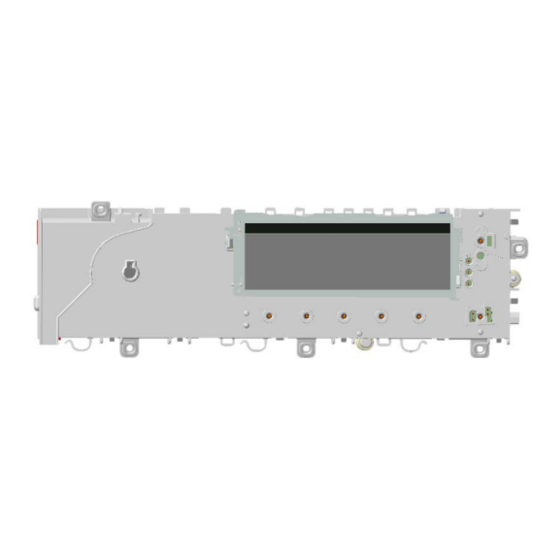
Page 119: Burning On The Circuit Boards Ewm25Xx/35Xx Wm/Wd
15 BURNING ON THE CIRCUIT BOARDS EWM25xx/35xx WM/WD In case of burning on the main circuit board, check that the problem is not caused by another electrical component (short-circuits, poor insulation, water leakage). Refer to the figures below in order to identify the component that might have caused the burning according to the position of the burned area. The circuit board shown below is the version with the greatest number of components: other boards may not feature all these components. -
Page 120: Burning On The Circuit Board Wd
16 BURNING ON THE CIRCUIT BOARD WD In case of burning on the main circuit board, check that the problem is not caused by another electrical component (short-circuits, poor insulation, water leakage). Refer to the figures below in order to identify the component that might have caused the burning according to the position of the burned area. The circuit board shown below is the version with the greatest number of components: other boards may not feature all these components. -
Page 121: Appendix
17 APPENDIX REVISION DATE DESCRIPTION 03/2009 Modification of Alarms E21-E22 page 17 / Alarm EF3 page 94 - Added control panels on pages 7/8 - Added weight sensor to position 6 on page 10 - Deleted last sentence on page 13 - Deleted two sentences in the paragraph "Rapid reading of alarms"...