Table of Contents
Quick Links
See also:
User Manual
Table of Contents
Troubleshooting

Related Manuals for Hitachi CB 520H B1


Summary of Contents for Hitachi CB 520H B1
- Page 1 Hitachi Compute Blade 500 Series System Service Manual Document Organization Product Version Getting Help Contents MK-91CB500004-30...
- Page 2 Hitachi, Ltd. Hitachi, Ltd., reserves the right to make changes to this document at any time without notice and assumes no responsibility for its use. This document contains the most current information available at the time of publication.
-
Page 3: Table Of Contents
Disk drive numbering: CB 520X B1/B2/B3 ............ 1-9 Disk drive numbering: Storage expansion blade .......... 1-10 Processor numbering: CB 520A A1 .............. 1-11 Processor numbering: CB 520H A1/B1/B2/B3/B4 ........... 1-11 Processor numbering: CB 540A A1/B1 ............ 1-12 Processor numbering: CB 520X B1/B2/B3 ............ 1-12 Hitachi Compute Blade 500 Series System Service Manual... - Page 4 Management module .................. 2-15 Switch module .................... 2-15 3 Basic knowledge for replacement ............ 3-1 Basic replacement procedure ................ 3-2 Server blade/ Management module/ Switch module ......... 3-2 Disk drive/ Power supply module/ Fan module .......... 3-3 Management monitor for maintenance .............. 3-3 Web Console .................... 3-3 Hitachi Compute Blade 500 Series System Service Manual...
- Page 5 Non-SMP CB 520X B1/B2/B3 .............. 4-52 Smart configure for SMP CB 520X B1/B2/B3 .......... 4-54 Restarting BMC procedure .................. 4-56 Power down procedure .................. 4-58 Server Blade .................... 4-58 Management module ................... 4-61 Power off the switch module ................ 4-62 Hitachi Compute Blade 500 Series System Service Manual...
- Page 6 Replacing a LOM pass through connector in full-wide server blade ...... 5-54 Removing a LOM pass through connector. ............. 5-55 Installing a LOM pass through connector. ............ 5-55 Replacing a USB enablement kit and USB in CB 520H A1/B1/B2 ...... 5-55 Hitachi Compute Blade 500 Series System Service Manual...
- Page 7 Replacing a SAS-kit 2 in CB 540A A1/B1 .............. 5-96 Removing a SAS-kit 2 .................. 5-96 Installing a SAS-kit 2 ................... 5-98 Replacing a SAS HDD kit in CB 520X B1/B2/B3 ............ 5-99 Removing a SAS HDD kit ................ 5-99 Hitachi Compute Blade 500 Series System Service Manual...
- Page 8 Replacing a shelf in the server chassis ............... 5-129 Removing a shelf for half-wide server blade .......... 5-129 Installing a shelf for half-wide server blade .......... 5-130 Removing a shelf for PCI expansion blade ........... 5-130 Installing a shelf for PCI expansion blade ............ 5-130 viii Hitachi Compute Blade 500 Series System Service Manual...
- Page 9 1Gb LAN switch module or 1/10Gb LAN switch module ........ 9-5 8Gb / 16Gb FC switch module ................ 9-8 10Gb DCB switch module ................ 9-12 10 Change LOM configuration ............. 10-1 Overviews of changing LOM configuration ............ 10-2 Hitachi Compute Blade 500 Series System Service Manual...
- Page 10 Getting help ...................... 11-2 Overview ...................... 11-2 Troubleshooting tables .................. 11-3 Power supply module troubleshooting table ........... 11-3 Cooling fan module troubleshooting table ............ 11-4 Management module troubleshooting table ........... 11-5 Server blade troubleshooting table .............. 11-7 Switch module troubleshooting table ............ 11-10 Web console troubleshooting table .............. 11-12 Hitachi Compute Blade 500 Series System Service Manual...
-
Page 11: Preface
This document describes how to use the Compute Blade 500 series. This preface includes the following information: Notice: The use of Compute Blade 500 series and all other Hitachi Data Systems products is governed by the terms of your agreement(s) with Hitachi Data Systems. -
Page 12: Safety Symbols
• When operating the equipment, follow the instructions and procedures in the manual. • Be sure to follow notes, cautionary statements and advice indicated on the equipment or in the manual. Preface Hitachi Compute Blade 500 Series System Service Manual... -
Page 13: General Safety Precautions
Before inserting the power plug, confirm that there is no dust or a ¢ water droplet on the plug. If any dust or water droplet is found, wipe it off with a dry cloth and then insert it. xiii Preface Hitachi Compute Blade 500 Series System Service Manual... - Page 14 (maximum of 4) from the electrical outlets. Removal of the cover or bracket Do not remove the cover or bracket. It can result in an electric shock, burns or equipment failure. Preface Hitachi Compute Blade 500 Series System Service Manual...
- Page 15 Contact with metal edges When moving the equipment or adding parts, take care not to hurt yourself on the metal or plastic edges. You can wear cotton gloves to protect your hands. Preface Hitachi Compute Blade 500 Series System Service Manual...
- Page 16 Risk of Explosion if Battery is replaced by an Incorrect Type. Dispose of Used Batteries According to the Instructions. Handling of batteries Since maintenance personnel should change batteries, do not change them yourself. Follow the instructions described below. Inappropriate Preface Hitachi Compute Blade 500 Series System Service Manual...
-
Page 17: Precautions Against Damage To Equipment
Do not insert any objects such as wire into them. Do not place the equipment in a place with metal pieces. If you do, a short circuit can be developed, causing equipment failure. xvii Preface Hitachi Compute Blade 500 Series System Service Manual... - Page 18 Doing so can cause a system unit failure. Handling hard disks A hard disk is a precision instrument. Handle it carefully when you use it. Inappropriate handling could result in hard disk failure. Faulty disk xviii Preface Hitachi Compute Blade 500 Series System Service Manual...
- Page 19 When you are using an OS which requires the shut down procedure, ¢ be sure to finish the shut down procedure before turning off the power. Otherwise, data may be lost. Rack Mount Safety Consideration Preface Hitachi Compute Blade 500 Series System Service Manual...
-
Page 20: Safety And Warning Labels
(e.g. use of power strips)." Safety and warning labels Server chassis The location and content of the warning and safety labels on the server chassis are shown here. Preface Hitachi Compute Blade 500 Series System Service Manual... -
Page 21: Server Blade
Server blade The following figures show the location and content of the safety and warning label on the server blade. Half-wide server blade / Full-wide server blade Preface Hitachi Compute Blade 500 Series System Service Manual... -
Page 22: Intended Audience
Compute Blade installation and to install the same. This document assumes the following: • The reader has a background in hardware installation of computer systems. xxii Preface Hitachi Compute Blade 500 Series System Service Manual... -
Page 23: Product Version
Chapter 9, Updating firmware Describes how to update firmware. Chapter 10, Change LOM Describes how to change LOM configuration. configuration Chapter 11, Troubleshooting Describes how to troubleshoot the Hitachi Compute Blade 500 Series. xxiii Preface Hitachi Compute Blade 500 Series System Service Manual... -
Page 24: Document Conventions
This term "Compute Blade" refers to all the models of the Compute Blade, unless otherwise noted. The Hitachi Virtualization Manager (HVM) name has been changed to Hitachi logical partitioning manager (LPAR manager, or LP). If you are using HVM based logical partitioning feature, substitute references to Hitachi logical partitioning manager (LPAR manager, or LP) with HVM. -
Page 25: Comments
Hitachi Data Systems Support Center, please visit the HDS website for current telephone numbers and other contact information: http://support.hds.com. Before calling the Hitachi Data Systems Support Center, please provide as much information about the problem as possible, including: •... - Page 26 Preface Hitachi Compute Blade 500 Series System Service Manual...
-
Page 27: Introduction
Introduction This chapter provides an overview of user maintenance and troubleshooting tasks for the Hitachi Compute Blade system. This chapter covers the following key topics: □ User replacement guidelines □ User maintenance tasks □ When a failure occurs □ System overview □... -
Page 28: User Replacement Guidelines
You can order and install the parts or perform the procedures. Figure 1-1 Identifying a failed part User maintenance tasks The maintenance tasks described in this manual follow the Hitachi Data Systems Customer Support program. • The Hitachi Data Systems self-service program allows users to perform allowable installation and configuration tasks and maintenance tasks on the Hitachi Compute Blade System. -
Page 29: When A Failure Occurs
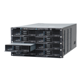
The Hitachi Compute Blade 500 series system can contain up to eight server blades and four switch modules. Compared with a 1U server chassis that contains a rack mount network switch and a FC switch, the 6U height Hitachi Compute Blade 500 server chassis offers improved features such as less space, fewer cables, and decreased weight. -
Page 30: Server Blade
"Half-wide server blade", "Full-wide server blade", "Storage expansion blade" for HDD, and "PCI expansion blade" for PCIe card, expanded with a "Half-wide blade". Introduction Hitachi Compute Blade 500 Series System Service Manual... - Page 31 CB 540A A1/B1 435.3 x 492.7 x 55.5 CB 520X B1/B2/B3 Expansion blade Storage expansion 435.3 x 492.7 x blade 55.5 PCI expansion blade 215.4 x 492.7 x 55.5 Figure 1-5 Server blades Introduction Hitachi Compute Blade 500 Series System Service Manual...
-
Page 32: Location
Server blade #2 Server blade #6 Server blade #3 Server blade #7 Management module numbering Figure 1-7 Location in server chassis Table 1-3 Location of installable components Symbol Component Management module #0 Introduction Hitachi Compute Blade 500 Series System Service Manual... -
Page 33: Switch Module Numbering
Switch module #3 Power supply module numbering Figure 1-9 Location in server chassis Table 1-5 Location of installable components Symbol Component Symbol Component Power supply module #0 Power supply module #2 Introduction Hitachi Compute Blade 500 Series System Service Manual... -
Page 34: Cooling Fan Module Numbering
The disk drive numbering in a server blade is #0 to #1 from the bottom to top, as viewed from the front of the server blade. The same numbering applies to all server blades in the server chassis. Figure 1-11 Disk drive location Introduction Hitachi Compute Blade 500 Series System Service Manual... -
Page 35: Disk Drive Numbering: Cb 540A A1/B1
The disk drive numbering in a server blade is #0 to #2 from the left to right, as viewed from the front of the server blade. The same numbering applies to all server blades in the server chassis. Introduction Hitachi Compute Blade 500 Series System Service Manual... -
Page 36: Disk Drive Numbering: Storage Expansion Blade
Numbering applies to all blades in the server chassis. Figure 1-14 Disk drive location Table 1-10 Location of installable components Symbol Component Symbol Component HDD #0 HDD #4 HDD #1 HDD #5 HDD #2 HDD #6 1-10 Introduction Hitachi Compute Blade 500 Series System Service Manual... -
Page 37: Processor Numbering: Cb 520A A1
The processor numbering in a server blade is #1 to #2 from the rear to front, as viewed from the front of the server blade. Figure 1-16 Processor location Table 1-12 Location of processors Symbol Component CPU #1 1-11 Introduction Hitachi Compute Blade 500 Series System Service Manual... -
Page 38: Processor Numbering: Cb 540A A1/B1
Processor numbering: CB 520X B1/B2/B3 The processor numbering in a server blade is #1 to #2 from the left to right, as viewed from the front of the server blade. Figure 1-18 Processor location 1-12 Introduction Hitachi Compute Blade 500 Series System Service Manual... -
Page 39: Dimm Numbering: Cb 520A A1
DIMM #10 DIMM #5 DIMM #11 DIMM #6 DIMM #12 DIMM numbering: CB 520H A1/B1/B2/B3/B4 The DIMM numbering in CB 520H A1/B1/B2/B3/B4 is #1 to #24 shown as following figure. 1-13 Introduction Hitachi Compute Blade 500 Series System Service Manual... -
Page 40: Dimm Numbering: Cb 540A A1/B1
DIMM #22 DIMM #11 DIMM #23 DIMM #12 DIMM #24 DIMM numbering: CB 540A A1/B1 The DIMM numbering in CB 540A A1/B1 is #1 to #48 shown as following figure. 1-14 Introduction Hitachi Compute Blade 500 Series System Service Manual... - Page 41 DIMM #21 DIMM #33 DIMM #45 DIMM #10 DIMM #22 DIMM #34 DIMM #46 DIMM #11 DIMM #23 DIMM #35 DIMM #47 DIMM #12 DIMM #24 DIMM #36 DIMM #48 1-15 Introduction Hitachi Compute Blade 500 Series System Service Manual...
-
Page 42: Dimm Numbering: Cb 520X B1/B2/B3
DIMM #19 DIMM #31 DIMM #43 DIMM #8 DIMM #20 DIMM #32 DIMM #44 DIMM #9 DIMM #21 DIMM #33 DIMM #45 DIMM #10 DIMM #22 DIMM #34 DIMM #46 1-16 Introduction Hitachi Compute Blade 500 Series System Service Manual... -
Page 43: Mezzanine Card Numbering: Cb 520A A1
DIMM #24 DIMM #36 DIMM #48 Mezzanine card numbering: CB 520A A1 Figure 1-23 Mezzanine card in server blade Table 1-19 Location of installable components Symbol Component Mezzanine #1 Mezzanine #2 1-17 Introduction Hitachi Compute Blade 500 Series System Service Manual... -
Page 44: Mezzanine Card Numbering: Cb 520H A1/B1/B2/B3/B4
Mezzanine #1 Mezzanine #2 Figure 1-25 Mezzanine card in server blade with LOM (CB 520H B1/B2/B3/B4) Table 1-21 Location of installable components Symbol Component LOM pass through connector Mezzanine #2 1-18 Introduction Hitachi Compute Blade 500 Series System Service Manual... -
Page 45: Mezzanine Card Numbering: Cb 540A A1/B1
Table 1-22 Location of installable components Symbol Component Symbol Component Mezzanine #1 Mezzanine #3 Mezzanine #2 Mezzanine #4 Figure 1-27 Mezzanine card in server blade with LOM (CB 540A B1) 1-19 Introduction Hitachi Compute Blade 500 Series System Service Manual... -
Page 46: Mezzanine Card Numbering: Cb 520X B1/B2/B3
Figure 1-28 Mezzanine card in server blade with LOM (CB 520X B1/B2/B3) Table 1-24 Location of installable components Symbol Component Symbol Component LOM pass through connector LOM pass through connector Mezzanine #2 Mezzanine #4 1-20 Introduction Hitachi Compute Blade 500 Series System Service Manual... -
Page 47: Mezzanine Card Numbering: Storage Expansion Blade
Symbol Component Mezzanine #1 Mezzanine #2 (Pass through mezzanine) Mezzanine #4 Figure 1-30 PCI card in storage expansion blade Table 1-26 Location of installable components Symbol Component PCI card #0 1-21 Introduction Hitachi Compute Blade 500 Series System Service Manual... -
Page 48: Mezzanine Card Numbering: Pci Expansion Blade
Figure 1-31 Mezzanine card in server/PCI expansion blade Table 1-27 Location of installable components Symbol Component Mezzanine #1 Mezzanine #2 (PCI blade connection kit F/H) Mezzanine #0 (PCI blade connection kit L/P) Mezzanine #4 1-22 Introduction Hitachi Compute Blade 500 Series System Service Manual... -
Page 49: Hot-Swappable Components
Hot-swappable components All installed modules or units are designed to be hot-swappable from the front or rear of the chassis. The following shows the hot-swap direction for each module or unit. 1-23 Introduction Hitachi Compute Blade 500 Series System Service Manual... -
Page 50: Indicators And Connectors
Figure 1-33 Hot-swappable components Indicators and connectors This section describes the switches, connectors, and LEDs on the Hitachi Compute Blade 500 series system. 1-24 Introduction Hitachi Compute Blade 500 Series System Service Manual... -
Page 51: Server Chassis
Normal operation Identify LED Blue-On The chassis is identified. This LED is controlled by the Web console, Blade Server Manager, or the (LID) Server Conductor The chassis is not identified. 1-25 Introduction Hitachi Compute Blade 500 Series System Service Manual... -
Page 52: Server Blade
(BZSTP) Server blade Figure 1-35 Half-wide Server blade (CB 520A A1, CB 520H A1/B1/B2) Figure 1-36 Half-wide Server blade (CB 520H B3/B4) Figure 1-37 Full-wide Server blade (CB 540A A1/B1) 1-26 Introduction Hitachi Compute Blade 500 Series System Service Manual... - Page 53 QPI Link Fault LED configuration. (Only for SMP CB 520X B1/B2/B3) Green-On QPI Link is linked up in SMP QPI Link Status LED configuration. (Only for SMP CB 520X B1/B2/B3) 1-27 Introduction Hitachi Compute Blade 500 Series System Service Manual...
- Page 54 The maximum temperature limit was exceeded. Amber-On A memory failure was detected. Not supported. Diagnostic Green-On The LED panel is active. Panel S BRD Amber-On The motherboard needs to be replaced. 1-28 Introduction Hitachi Compute Blade 500 Series System Service Manual...
-
Page 55: Disk Drive
Disk drive is accessing or rebuilding. Fault LED Amber-ON A serious error has occurred. Amber-Blink 5Hz: The host is locating the position of the disk drive. 1Hz: Disk drive is rebuilding. 1-29 Introduction Hitachi Compute Blade 500 Series System Service Manual... -
Page 56: Management Module
Power is not supplied to the server blade. Identify LED (LID) Blue-On The management module is identified. Alarm LED (ALM) Red-On A serious error has occurred in the management module. 1-30 Introduction Hitachi Compute Blade 500 Series System Service Manual... -
Page 57: 1Gb/Sec Lan Pass Through Module
The LAN pass through module is not identified Power LED Green-On Power-on and normal operation. (PWR) The power fails or no power supplied. 1Gb LAN switch module (20 ports) Figure 1-42 1Gb LAN switch module 1-31 Introduction Hitachi Compute Blade 500 Series System Service Manual... -
Page 58: 1Gb Lan Switch Module (40 Ports)
Green-Blink Link activity. Port is sending or receiving data. Amber-On Link failed. Memory Card slot (MC) - Slot for an SD memory card. Access LED (ACC) Green-On The SD memory card is accessed. 1-32 Introduction Hitachi Compute Blade 500 Series System Service Manual... -
Page 59: 1/10Gb Lan Switch Module
A link is established on 10BASE-R and the port is sending or receiving data. The port is neither sending nor receiving data. LINK LED for XFP Green-On A link is established on 10BASE-R. 1-33 Introduction Hitachi Compute Blade 500 Series System Service Manual... -
Page 60: Brocade 8Gb Fibre Channel Switch Module
FC ports 0- 5 These connectors are equipped with optical modules (SFP+). Connect a fibre channel cable to this optical module. FC port diagnosis LED Amber-On Signal is received but not on line. 1-34 Introduction Hitachi Compute Blade 500 Series System Service Manual... -
Page 61: Brocade 16Gb Fibre Channel Switch Module/16Gb Fibre Channel Switch Module2
Power-On and normal operation. The power fails or no power supplied. Status LED Green-On Normal operation. Green-Blink During power-on diagnosis or booting software. Amber-Blink The over temperature threshold or any warning conditions. 1-35 Introduction Hitachi Compute Blade 500 Series System Service Manual... -
Page 62: Brocade 10Gb Dcb Switch Module
Power LED (PWR) Green-On Power-on and normal operation. The power fails or no power supplied. Identify LED (LOCID) Blue-On The switch module is identified The switch module is not identified 1-36 Introduction Hitachi Compute Blade 500 Series System Service Manual... -
Page 63: 10Gb Lan Pass Through Module/10Gb Lan Pass Through Module2
Amber-On A serious failure detected. (Flashing during LED test of power-on diagnosis, it is not a failure.) Amber-Blink The warning detected. (The switch operates, but the function is reconfigured 1-37 Introduction Hitachi Compute Blade 500 Series System Service Manual... -
Page 64: Power Supply Module
Green-Blink Standby condition (input power is OK). Amber-On Failures or shutdown the system Amber-Blink No input power to this power supply, but input power is supplied to others. No power supplied. Inlet IEC60320-C20 1-38 Introduction Hitachi Compute Blade 500 Series System Service Manual... -
Page 65: Cooling Fan Module
• Management module Required: • Switch module Follow the replacement instruction in this manual. • Fan module • Power supply • Front panel module • Disk drive 1-39 Introduction Hitachi Compute Blade 500 Series System Service Manual... - Page 66 Figure 1-51 Color code for maintenance 1-40 Introduction Hitachi Compute Blade 500 Series System Service Manual...
-
Page 67: Replaceable Parts
Replaceable parts The replaceable parts for the Hitachi Compute Blade System are described in this chapter. They can be replaced with the power turned on. This chapter covers the following key topics: □ Overview □ Server chassis □ Server blade □... -
Page 68: Overview
Overview The following parts in the Hitachi Compute Blade system are replaceable. These are illustrated and described on the following pages. Table 2-1 Replaceable parts overview Customer No customer Description replaceable replaceable parts (FE only) Module/Unit Parts parts. F/W update... -
Page 69: Server Chassis
If the "Flash drive" is installed in "PCI blade card adapter F/H", the "Flash drive" is the "Customer replaceable. parts". Server chassis This section displays the replaceable parts on the base unit. Replaceable parts Hitachi Compute Blade 500 Series System Service Manual... -
Page 70: Replaceable Parts- Front Side
LCD touch console GG-DT3LCD1X1-R KVM cable GG-LR3KVM1X1-R Half-wide server blade CB 520A A1 CB 520H A1/B1/B2/B3/B4 Full-wide server blade CB 540A A1/B1 CB 520X B1/B2/B3 Storage expansion blade PCI expansion blade Replaceable parts Hitachi Compute Blade 500 Series System Service Manual... -
Page 71: Replaceable Parts- Rear Side
8Gb fibre channel switch module GV-BE2FSW1X1-R 16Gb fibre channel switch module GV-BE2FSW3X1-R 10Gb DCB switch module GG-BE3LSW3X1-R GV-BE2LSW3X1-R 10Gb LAN pass through module GG-BE3LPS2X1-R 10Gb LAN pass through module2 GG-BE3LPS2X2-R Replaceable parts Hitachi Compute Blade 500 Series System Service Manual... -
Page 72: Replaceable Parts - Mechanical Components
Dummy server blade GG-BE3SVMDX1-Y Dummy management module GG-BE3SVPDX1-Y Dummy switch module GG-BE3SWMDX1-Y Dummy power supply module GG-BE3PSMDX1-Y Shelf Shelf for half-wide server blade GG-BE3SHL1X1-Y Shelf for PCI expansion blade GG-BE3SHL2X1-Y Replaceable parts Hitachi Compute Blade 500 Series System Service Manual... -
Page 73: Server Blade
Figure 2-5 Replaceable components- CB 520A A1 CB 520H A1/B1/B2/B3/B4 This section shows the replaceable parts on the CB 520H A1. Figure 2-6 Replaceable components- CB 520H A1 without LOM Replaceable parts Hitachi Compute Blade 500 Series System Service Manual... - Page 74 Figure 2-7 Replaceable components- CB 520H B1/B2 Figure 2-8 Replaceable components- CB 520H B3/B4 CB 540A A1/B1 This section shows the replaceable parts on the CB 540A A1/B1. Replaceable parts Hitachi Compute Blade 500 Series System Service Manual...
-
Page 75: Cb 520X B1/B2/B3
Figure 2-9 Replaceable components- CB 540A A1 Figure 2-10 Replaceable components- CB 540A B1 CB 520X B1/B2/B3 This section shows the replaceable parts on the CB 520X B1/B2/B3. Replaceable parts Hitachi Compute Blade 500 Series System Service Manual... -
Page 76: Expansion Blade
Figure 2-11 Replaceable components- CB 520X B1/B2/B3 Figure 2-12 Replaceable components- CB 520X B1/B2/B3 for SMP Expansion blade Storage expansion blade This section shows the replaceable parts on the storage expansion blade. 2-10 Replaceable parts Hitachi Compute Blade 500 Series System Service Manual... -
Page 77: Pci Expansion Blade
4 GB DDR3 1R RDIMM 1333 MHz GG-MJ3N4G1X1-R 8 GB DDR3 2R RDIMM 1333 MHz GG-MJ3N8G1X1-R 16 GB DDR3 2R RDIMM 1333 MHz GG-MJ316G1X1-R 32 GB DDR3 4R RDIMM 1333 MHz GG-MJ332G1X1-R 2-11 Replaceable parts Hitachi Compute Blade 500 Series System Service Manual... - Page 78 SAS canister unit, 300 GB 10000 rpm, w/o BNST GG-UH33001X1C-R SAS canister unit, 300 GB 15000 rpm GG-UH33002X1-R SAS canister unit, 300 GB 15000 rpm, w/o BNST GG-UH33002X1C-R SAS canister unit, 600 GB 10000 rpm GG-UH36001X1-R 2-12 Replaceable parts Hitachi Compute Blade 500 Series System Service Manual...
- Page 79 Mezzanine card 1Gb 4 port Ethernet GG-CN3M1G2X1-R 1Gb 8 port Ethernet GG-CN3M1G3X1-R 10Gb 4 port CNA GG-CN3MXG2X1-R 10Gb 4 port LAN GG-CN3MXG2X2-R Hitachi 8Gb 2 port fibre channel GG-CC3M8G2X1-R 2-13 Replaceable parts Hitachi Compute Blade 500 Series System Service Manual...
- Page 80 NVIDIA GRID K2 GPU adapter GG-CV3GPU2X1-R NVIDIA TESLA K10 GPGPU adapter GG-CV3GPU4X1-R 2-blade SMP connection board GG-EZ3SMB4X1-R 4-blade SMP connection board GG-EZ3SMB8X1-R SD card SD card enablement kit GG-CH3SEK1X1-R SD card GG-MC3SDC1X1-R 2-14 Replaceable parts Hitachi Compute Blade 500 Series System Service Manual...
-
Page 81: Management Module
Part Name Spare Part No. 10 Gb SFP+ twinax cable GG-LN3TWC1X1-R GG-LN3TWC2X1-R GG-LN3TWC3X1-R Memory Memory card for 1Gb, 1/10Gb LAN GG-MC3LSC1X1-R switch USB memory for 8Gb fibre channel GV-MC2USB1X1-R switch 2-15 Replaceable parts Hitachi Compute Blade 500 Series System Service Manual... - Page 82 SFP+ module for 16Gb FC 16Gb FC SFP+, SWL for FC Switch GV-BE2SFP6X1-R switch 16Gb FC SFP+, LWL, 10 km GV-BE2SFP7X1-R 16Gb FC SFP+, ELWL, 25 km GV-BE2SFP8X1-R 2-16 Replaceable parts Hitachi Compute Blade 500 Series System Service Manual...
-
Page 83: Basic Knowledge For Replacement
The following key topics are covered: This chapter provides an overview. Details are found in chapters 4 and 5. □ Basic replacement procedure □ Management monitor for maintenance □ Preventing electrostatic charge Basic knowledge for replacement Hitachi Compute Blade 500 Series System Service Manual... -
Page 84: Basic Replacement Procedure
Basic replacement procedure Server blade/ Management module/ Switch module Figure 3-1 Basic procedure 1 Basic knowledge for replacement Hitachi Compute Blade 500 Series System Service Manual... -
Page 85: Disk Drive/ Power Supply Module/ Fan Module
LCD touch console (option) Web Console A Web console is the general application to control or manage the Hitachi Compute Blade system. Connecting between management modules installed in the system and the user console PC on the network, you can display the system status and the failed part, and also set up the configuration. -
Page 86: Lcd Touch Console
For more information about the LCD application, see Hitachi Compute Blade 500 LCD Touch Console User's Guide. Hitachi recommends that the LCD touch console is available as the secondary maintenance application. The LCD touch console is directly connected to the USB port #0 or 1 on the front panel module. -
Page 87: Preventing Electrostatic Charge
Notice: To prevent electrostatic damage, put on an anti-static wrist strap before handling components. Figure 3-5 Anti-static attachment at the front of the server chassis Basic knowledge for replacement Hitachi Compute Blade 500 Series System Service Manual... - Page 88 Figure 3-6 Anti-static attachment at the rear of the server chassis Basic knowledge for replacement Hitachi Compute Blade 500 Series System Service Manual...
-
Page 89: Common Process For Replacement
□ Restoring MAPS action settings of 16Gb FC switch module □ Backup/restore procedure □ Time of Day (TOD) clock setup procedure □ Smart configure procedure for server blade □ Restarting BMC procedure Common process for replacement Hitachi Compute Blade 500 Series System Service Manual... - Page 90 □ Power down procedure Common process for replacement Hitachi Compute Blade 500 Series System Service Manual...
-
Page 91: Preparation For Replacement
The few minutes you spend ahead of time can save you a lot of time later. Observe the following guidelines when working on Hitachi Compute Blade. Ignorance or violation of these guidelines may result in bodily injury or damage to the server chassis or parts. -
Page 92
The web console portal is displayed on the screen. Enter
and , and then click Login. When the login process is successful, the dashboard is displayed. Figure 4-2 Web console Login screen Common process for replacement Hitachi Compute Blade 500 Series System Service Manual... -
Page 93: Alert Information Identification Procedure
Select the event log that you need to get the detail. Click Show details. The show details dialog box will appear. See the Failure information and Action plan columns for maintenance. Common process for replacement Hitachi Compute Blade 500 Series System Service Manual... -
Page 94: To Identify The Mar Log
Select the event log that you need to get the detail. Click Show details. The show details dialog box will appear. See the Failure information and Action plan columns for maintenance. Common process for replacement Hitachi Compute Blade 500 Series System Service Manual... -
Page 95: To Download The Mar Log
Modules > Server Blade n of the SMP configuration > a target blade that you should replace. Select Condition tab, and then click LID ON. The confirmation dialog box appears. Click OK. Common process for replacement Hitachi Compute Blade 500 Series System Service Manual... -
Page 96: Management Module
Select Condition tab, and then click LID ON. The confirmation dialog box appears. Click OK. LID: OFF Select Condition tab, and then click LID OFF. The confirmation dialog box appears. Click OK. Common process for replacement Hitachi Compute Blade 500 Series System Service Manual... -
Page 97: Switch Module
Select Condition tab, and then click LID ON. The confirmation dialog box appears. Click OK. LID: OFF Select Condition tab, and then click LID OFF. The confirmation dialog box appears. Click OK. Common process for replacement Hitachi Compute Blade 500 Series System Service Manual... -
Page 98: Maintenance Mode On/Off Procedure
Maintenance mode ON. If you need to do maintenance for more than two hours, you MUST activate Maintenance mode again. 4-10 Common process for replacement Hitachi Compute Blade 500 Series System Service Manual... -
Page 99: Server Blade
The confirmation dialog box appears. Click OK. Figure 4-8 Maintenance mode on Confirm that the selected module is highlighted and the message is displayed. Figure 4-9 Highlighting the activated module 4-11 Common process for replacement Hitachi Compute Blade 500 Series System Service Manual... - Page 100 Click check boxes of the SMP blades that should be changed to maintenance mode, and then click Confirm. In Confirm dialog box, click OK. Confirm that the selected blades highlighted and a symbol is indicated. 4-12 Common process for replacement Hitachi Compute Blade 500 Series System Service Manual...
- Page 101 Confirm. The confirmation dialog box appears. Click OK. Confirm that the highlights of the selected blades go out and the symbol disappears. 4-13 Common process for replacement Hitachi Compute Blade 500 Series System Service Manual...
-
Page 102: Management Module
Management modules > a target module that should be changed into maintenance mode. Click Action, and then select Maintenance mode ON. The confirmation dialog box appears. Click OK. 4-14 Common process for replacement Hitachi Compute Blade 500 Series System Service Manual... -
Page 103: Switch Module
> a target module that should be changed into maintenance mode. Click Action, and then select Maintenance mode ON. The current setting condition will be displayed. Click Confirm. 4-15 Common process for replacement Hitachi Compute Blade 500 Series System Service Manual... - Page 104 Click Action, and then select Maintenance mode OFF. The confirmation dialog box appears. Click OK. Confirm that the highlight of the selected module goes out and the message is off. 4-16 Common process for replacement Hitachi Compute Blade 500 Series System Service Manual...
-
Page 105: Server Chassis
The confirmation dialog box appears. Click OK. Figure 4-16 Maintenance mode on Confirm that the chassis or front panel is highlighted and the message is displayed. Figure 4-17 Highlighting the activated module 4-17 Common process for replacement Hitachi Compute Blade 500 Series System Service Manual... -
Page 106: Internal Ip Address Setup Procedure For Switch Module
Network > Management LAN that should identify the IP address. Select IP Address tab. Check and record the internal IP address, Subnet Mask, and Default Gateway for the switch module. 4-18 Common process for replacement Hitachi Compute Blade 500 Series System Service Manual... -
Page 107: Edit Internal Ip Address For Switch Module
Select Resources tab on the web console and select Systems > Network > Management LAN that should identify the IP address. Select IP Address tab. Click Edit. 4-19 Common process for replacement Hitachi Compute Blade 500 Series System Service Manual... - Page 108 For the switch module you are working on, select Connect through management LAN port. Enter the switch module's IP Address, Subnet Mask, and Default Gateway that conforms to the internal CB 500 network environment. Click Confirm. 4-20 Common process for replacement Hitachi Compute Blade 500 Series System Service Manual...
- Page 109 Figure 4-21 Edit IP Address window Confirmation window is displayed. Click OK. 4-21 Common process for replacement Hitachi Compute Blade 500 Series System Service Manual...
-
Page 110: F/W Version Identification Procedure
You should identify the firmware version before replacing the failed component even if the configuration data such as firmware, FRU information and so on is backed up automatically. 4-22 Common process for replacement Hitachi Compute Blade 500 Series System Service Manual... -
Page 111: Server Blade
Modules > Management Module > target module that should identify the version. Select Condition tab. Check and record the Firmware version, Dictionary version, and Equipment parameter version for maintenance. 4-23 Common process for replacement Hitachi Compute Blade 500 Series System Service Manual... -
Page 112: Switch Module
Modules > Switch Modules > target module that should identify the version. Select Condition tab. Check and record the Firmware version for maintenance. Figure 4-26 Identifying F/W version 4-24 Common process for replacement Hitachi Compute Blade 500 Series System Service Manual... -
Page 113: Confirming Switch Mode Of Fc Switch Module
The login prompt is displayed in the terminal. Figure 4-27 Connecting to FC switch module Enter admin as login name, and then press Enter key. Enter password as password, and then press Enter key. 4-25 Common process for replacement Hitachi Compute Blade 500 Series System Service Manual... - Page 114 Enter mapsconfig --show, and then press Enter key. Confirm the message in Configured Notification line and identify the MAPS action settings. The MAPS action settings are RASLOG, SNMP, SW_CRITICAL, SW_MARGINAL, and SFP_MARGINAL, at the maximum. 4-26 Common process for replacement Hitachi Compute Blade 500 Series System Service Manual...
-
Page 115: Restoring Switch Mode Of Fc Switch Module
< IP address >:IP address for the target switch module. See Internal IP address setup procedure for switch module on page 4-18 section. The login prompt is displayed in the terminal. 4-27 Common process for replacement Hitachi Compute Blade 500 Series System Service Manual... - Page 116 Enter ag --modeenable, and then press Enter key. Enter y when "Do you want to continue? (yes, y, no, n): [no]" is indicated, and then press Enter key. 4-28 Common process for replacement Hitachi Compute Blade 500 Series System Service Manual...
- Page 117 Enter key to set MAPS mode. Enter y when "Do you want to continue? (yes, y, no, n): [no]" is indicated, and then press Enter key. 4-29 Common process for replacement Hitachi Compute Blade 500 Series System Service Manual...
-
Page 118: Restoring Maps Action Settings Of 16Gb Fc Switch Module
The configuration data of switch module is NOT automatically backed up. Hitachi strongly recommends that you should back up the data of the switch module before starting replacement procedure. 4-30... -
Page 119: Server Blade
The confirmation dialog box appears. Click OK and then the firmware restore process will be started. After the firmware restore process has completed, the successful message dialog box appears. Click Close. 4-31 Common process for replacement Hitachi Compute Blade 500 Series System Service Manual... -
Page 120: Management Module
Select Resources tab and select Modules > All Modules > Management modules. Click Action and then select Backup Settings. The Confirmation window appears. Click Backup. The progress window is displayed. 4-32 Common process for replacement Hitachi Compute Blade 500 Series System Service Manual... - Page 121 Tip: If you do not need to back up the configuration data to the local PC, click Cancel in step 7. In this case, the configuration data is backed up just into the USB memory in the front panel. 4-33 Common process for replacement Hitachi Compute Blade 500 Series System Service Manual...
- Page 122 Figure 4-33 Restore the configuration data for management module After the firmware restore process has completed, the successful message dialog box appears. Click Close. The management module will reboot automatically. 4-34 Common process for replacement Hitachi Compute Blade 500 Series System Service Manual...
-
Page 123: Switch Module
< IP address >:IP address for the target switch module. See Internal IP address setup procedure for switch module on page 4-18 section. The login prompt is displayed in the terminal. 4-35 Common process for replacement Hitachi Compute Blade 500 Series System Service Manual... - Page 124 Enter backup ftp < IP Address > < backup file name.dat> no- software, and then press Enter key. Enter upload, and then press Enter key. Enter password, and then press Enter key. 4-36 Common process for replacement Hitachi Compute Blade 500 Series System Service Manual...
- Page 125 Enter restore ftp < IP Address > < backup file name.dat> no- software, and then press Enter key. Enter upload, and then press Enter key. Enter password, and then press Enter key. The following message is displayed. 4-37 Common process for replacement Hitachi Compute Blade 500 Series System Service Manual...
- Page 126 < IP address >:IP address for the target switch module. See Internal IP address setup procedure for switch module on page 4-18 section. The login prompt is displayed in the terminal. 4-38 Common process for replacement Hitachi Compute Blade 500 Series System Service Manual...
- Page 127 Enter configupload, and then press Enter key. Enter ftp, and then press Enter key. Enter < IP Address > for console PC, and then press Enter key. 4-39 Common process for replacement Hitachi Compute Blade 500 Series System Service Manual...
- Page 128 Confirm that the command prompt is indicated. Enter switchdisable, and then press Enter key. Enter configdownload, and then press Enter key. Enter ftp, and then press Enter key. 4-40 Common process for replacement Hitachi Compute Blade 500 Series System Service Manual...
-
Page 129: 10Gb Dcb Switch Module
The Connection Description window is displayed. Enter telnet1, and then click OK. Select TCP/IP (Winsock), enter < IP address > in the Host address box, and then click OK. 4-41 Common process for replacement Hitachi Compute Blade 500 Series System Service Manual... -
Page 130
Enter password as password, and then press Enter key. Confirm that the command prompt is indicated. Enter copy startup-config ftp://upload:password@< IP Address for console PC >/
, and then press Enter key. 4-42 Common process for replacement Hitachi Compute Blade 500 Series System Service Manual... - Page 131 Confirm whether the indicated licenses include the authorized licenses which confirmed in the procedure of Confirming NOS version and VCS/FCoE license of 10Gb DCB switch module before the replacement. 4-43 Common process for replacement Hitachi Compute Blade 500 Series System Service Manual...
-
Page 132: Time Of Day (Tod) Clock Setup Procedure
[Output example when VCS and FCoE licenses are authorized] Transfer the licenses from the failed DCB switch module to the installed DCB switch module. Note: For detail about transferring license procedure, consult with Hitachi Data System Support team. Time of Day (TOD) clock setup procedure The TOD (Time Of Day) clock setting is critical to the integrity of the error log and event log. -
Page 133: Management Module
Select Administration tab on the web console and select Date and Time. Select Local Time tab and then click Edit. The dialog box for edit appears. Input local time in your environment. Click Submit. 4-45 Common process for replacement Hitachi Compute Blade 500 Series System Service Manual... - Page 134 Select NTP tab and then click Edit. The dialog box for edit appears. Input NTP in your environment. Click Confirm. The confirmation dialog box appears. Click OK. 4-46 Common process for replacement Hitachi Compute Blade 500 Series System Service Manual...
-
Page 135: Server Blade
Blades > Sever Blade n of SMP configuration > a target module that should identify TOD Select BMC tab. Check and record the some information for maintenance. Figure 4-42 Identifying TOD clock information in BMC 4-47 Common process for replacement Hitachi Compute Blade 500 Series System Service Manual... - Page 136 Click Edit, and select BMC time. The dialog box for editing appears. Input local time in your environment. Click Confirm. The confirmation dialog box appears. Click OK. Figure 4-43 Editing local time 4-48 Common process for replacement Hitachi Compute Blade 500 Series System Service Manual...
-
Page 137: Switch Module
The login prompt is displayed in the terminal. Figure 4-44 Login to the terminal software Enter operator as login name, and then press Enter key. Confirm that the command prompt is indicated. 4-49 Common process for replacement Hitachi Compute Blade 500 Series System Service Manual... - Page 138 < IP address >:IP address for the target switch module. See Internal IP address setup procedure for switch module on page 4-18 section. The login prompt is displayed in the terminal. 4-50 Common process for replacement Hitachi Compute Blade 500 Series System Service Manual...
- Page 139 Confirm that the command prompt is indicated. Enter date, and then press Enter key. To edit TOD; Enter date "< mmddhhmmyy >", and then press Enter key. mm/dd/hh/mm/yy :month/ day/ hour/ minute/ year 4-51 Common process for replacement Hitachi Compute Blade 500 Series System Service Manual...
-
Page 140: Smart Configure Procedure For Server Blade
> target server blade. Select Condition tab. Click Server Blade Action and then select Run Smart configure. The confirmation dialog box appears. Click OK. Smart configure process will be started. 4-52 Common process for replacement Hitachi Compute Blade 500 Series System Service Manual... - Page 141 If it is still displayed as In Progress, repeat the procedure step 6 and step 7. When it was displayed as Configured, the smart configure process is completed. 4-53 Common process for replacement Hitachi Compute Blade 500 Series System Service Manual...
- Page 142 > Server Blade n of the SMP configuration > primary blade. Select Condition tab. Click Server Blade Action and then select Run Smart configure. The confirmation dialog box appears. Click OK. Smart configure process will be started. 4-54 Common process for replacement Hitachi Compute Blade 500 Series System Service Manual...
- Page 143 If it is still displayed as In Progress, repeat the procedure step 6 and step 7. When it was displayed as Configured, the smart configure process is completed. 4-55 Common process for replacement Hitachi Compute Blade 500 Series System Service Manual...
-
Page 144: Restarting Bmc Procedure
Select Resources tab and select Modules > All Modules > Server Blades > Server Blade n of the SMP configuration > Server Blade n (Primary). Click BMC > Restart BMC in lower right pane. 4-56 Common process for replacement Hitachi Compute Blade 500 Series System Service Manual... - Page 145 Date and Time, which indicates the firmware update completing time, in lower right System Event Log pane. Click Refresh whenever you want to display the latest System Event Log. 4-57 Common process for replacement Hitachi Compute Blade 500 Series System Service Manual...
-
Page 146: Power Down Procedure
Logon to the web console and select Resource. Select Modules > All Modules > Server blades > the failed server blade. Select Condition tab. Click Power OFF. 4-58 Common process for replacement Hitachi Compute Blade 500 Series System Service Manual... - Page 147 (Note: "n" indicates the slot number of the primary blade.) Select Condition tab. Click Power OFF. Ensure that the shutdown was completed and the Power LED blinks in green. 4-59 Common process for replacement Hitachi Compute Blade 500 Series System Service Manual...
- Page 148 Ensure that Power LED lights in green. Press and hold the Power switch for four seconds or more. The Power LED turns blink in green. Release the Power switch. 4-60 Common process for replacement Hitachi Compute Blade 500 Series System Service Manual...
-
Page 149: Management Module
Select Modules > All Modules > Management modules > the failed module. Click Action and then select Shutdown. Ensure that the shutdown was completed and Power LED lights in amber. 4-61 Common process for replacement Hitachi Compute Blade 500 Series System Service Manual... -
Page 150: Power Off The Switch Module
Select Modules > All Modules > Switch modules > the failed module. Select Condition tab. Click Power OFF. Ensure that the shutdown was completed and Power LED lights in amber. 4-62 Common process for replacement Hitachi Compute Blade 500 Series System Service Manual... - Page 151 Figure 4-55 Power off procedure for failed switch module 4-63 Common process for replacement Hitachi Compute Blade 500 Series System Service Manual...
- Page 152 4-64 Common process for replacement Hitachi Compute Blade 500 Series System Service Manual...
-
Page 153: Replacing Parts
Replacing parts This chapter describes how to remove and install parts on the Hitachi Compute Blade system. The following key topics are covered: □ Replacing a server blade □ Replacing an SMP connection board for CB 520X B1/B2/B3 □ Replacing an expansion blade □... - Page 154 □ Replacing a LAN pass through module, LAN pass through module2 □ Replacing an SFP+ module □ Replacing a memory card for LAN switch module □ Replacing a USB memory for 8Gb FC switch module Replacing parts Hitachi Compute Blade 500 Series System Service Manual...
- Page 155 □ Replacing a fan module □ Replacing a front panel module □ Replacing a USB memory in the front panel module □ Replacing a dummy module □ Replacing a shelf in the server chassis Replacing parts Hitachi Compute Blade 500 Series System Service Manual...
-
Page 156: Replacing A Server Blade
Replacing a server blade The hot-swappable feature of the Hitachi Compute Blade 500 series system allows server blade replacement with the server chassis power ON. This procedure describes how to replace a server blade when the server chassis power is on. - Page 157 Identify LED (LID) on/off procedure on page 4-7 section. If you need to update the BMC and/or EFI firmware, consult with Hitachi Data Systems Customer Support team. Restore the blade configuration data (FRU/ BMC configuration/ EFI configuration) from the automatic back up field in server chassis. See Backup/restore procedure on page 4-30 section.
-
Page 158: Removing A Full-Wide Server Blade
Release the blue lock tab and pull the lever, as shown below. Holding the server blade, carefully slide out from the chassis and place it on an anti-static mat. Figure 5-3 Removing the full-wide server blade Notice: Replacing parts Hitachi Compute Blade 500 Series System Service Manual... - Page 159 Identify LED (LID) on/off procedure on page 4-7 section. If you need to update the BMC and/or EFI firmware, consult with Hitachi Data Systems Customer Support team. Restore the Blade configuration data (FRU/ BMC configuration/ EFI configuration) from the automatic back up field in server chassis. See Backup/restore procedure on page 4-30 section.
-
Page 160: Removing An Smp Connection Board
2. Do not pull out the SMP connection board at a tilt. Connectors in the board may be damaged. 3. Do not touch the socket pins. The pins are physically sensitive. Replacing parts Hitachi Compute Blade 500 Series System Service Manual... -
Page 161: Installing An Smp Connection Board
Figure 5-5 Removing 2-blade SMP connection board Figure 5-6 Removing 4-blade SMP connection board Installing an SMP connection board Put on an anti-static wrist strap. Replacing parts Hitachi Compute Blade 500 Series System Service Manual... - Page 162 SMP connection board and blades becomes about 10 mm with the lever fully open. Close a lever to the lever latched. Figure 5-7 Installing 2-blade SMP connection board 5-10 Replacing parts Hitachi Compute Blade 500 Series System Service Manual...
-
Page 163: Replacing An Expansion Blade
Figure 5-8 Installing 4-blade SMP connection board Replacing an expansion blade The hot-swappable feature of the Hitachi Compute Blade system allows the expansion blade replacement with the server chassis power ON. This procedure describes how to replace the expansion blade when the server chassis power is on. -
Page 164: Installing A Storage Expansion Blade
Identify LED (LID) on/off procedure on page 4-7 section. If you need to update the BMC and/or EFI firmware, consult with Hitachi Data Systems Customer Support team. Restore the Blade configuration data (FRU/ BMC configuration/ EFI configuration) from the automatic back up field in server chassis. See Backup/restore procedure on page 4-30 section. - Page 165 OS to Disabled by using - (minus) key, and then press Enter. (Skip this step when the HDD in server blade is assigned to Boot disk.) Confirm that the Boot Support column changes to Disabled. 5-13 Replacing parts Hitachi Compute Blade 500 Series System Service Manual...
- Page 166 Perform the smart configure process. Smart configure procedure for server blade on page 4-52 section. Verify that the replacement was successful through the MAR log. Alert information identification procedure on page 4-5 section. 5-14 Replacing parts Hitachi Compute Blade 500 Series System Service Manual...
-
Page 167: Removing A Pci Expansion Blade From Server Chassis
Release the blue lock tab and pull the lever, as shown below. Holding the server blade, carefully slide out from the chassis and place it on an anti-static mat. Figure 5-11 Removing the PCI expansion blade Notice: 5-15 Replacing parts Hitachi Compute Blade 500 Series System Service Manual... -
Page 168: Installing A Pci Expansion Blade Into Server Chassis
Identify LED (LID) on/off procedure on page 4-7 section. If you need to update the BMC and/or EFI firmware, consult with Hitachi Data Systems Customer Support team. Restore the Blade configuration data (FRU/ BMC configuration/ EFI configuration) from the automatic back up field in server chassis. See Backup/restore procedure on page 4-30 section. -
Page 169: Replacing A Half-Wide Server Blade For Storage Expansion Blade
Replacing a half-wide server blade for storage expansion blade The hot-swappable feature of the Hitachi Compute Blade 500 series system allows the replacement of the server blade for storage expansion blade with the server chassis power on. This procedure describes how to replace a... - Page 170 Pull the latch against bottom plate with your finger to release the latch. While releasing the latch in the center of the bottom plate, slide out the server blade. 5-18 Replacing parts Hitachi Compute Blade 500 Series System Service Manual...
-
Page 171: Installing A Server Blade With A Storage Expansion Blade
Open the top cover of the server blade. See Opening a top cover, Server blade on page 5-38 section. Figure 5-17 Installing a server blade on the storage expansion blade 5-19 Replacing parts Hitachi Compute Blade 500 Series System Service Manual... - Page 172 Close the latches of the pass through mezzanine card. Figure 5-19 Fixing the pass through mezzanine component Tighten two screws to fix the cable connector onto the expansion blade. 5-20 Replacing parts Hitachi Compute Blade 500 Series System Service Manual...
-
Page 173: Replacing A Half-Wide Server Blade For Pci Expansion Blade
Replacing a half-wide server blade for PCI expansion blade The hot-swappable feature of the Hitachi Compute Blade 500 series system allows server blade for PCI expansion blade replacement with the server chassis power-on. This procedure describes how to replace a server blade for PCI expansion blade when the server chassis power is on. - Page 174 Pull out the connection board of the connection kit L/P in the server blade straight upward. See Figure 5-25 Removing the connection kit L/P on page 5-24. Figure 5-21 Location of the connection kit 5-22 Replacing parts Hitachi Compute Blade 500 Series System Service Manual...
- Page 175 Figure 5-22 Removing the connection kit F/H Figure 5-23 Removing the connection kit L/P 5-23 Replacing parts Hitachi Compute Blade 500 Series System Service Manual...
- Page 176 Lift up the server blade side with the tilt angle of less than 45 degree. While pulling down the latch against the bottom plate with your finger to release the latch, slide the server blade toward outer side. 5-24 Replacing parts Hitachi Compute Blade 500 Series System Service Manual...
-
Page 177: Installing A Server Blade With The Pci Expansion Blade
(Confirm that the server blade does not slide toward opposite side.) Open the top cover of the server blade. Opening a top cover, Server blade on page 5-38 section. 5-25 Replacing parts Hitachi Compute Blade 500 Series System Service Manual... - Page 178 Push and opposite side at the same time. Figure 5-28 Inserting the connection kit L/P Put in the connection bracket, and then tighten a thumbscrew of the connection bracket. 5-26 Replacing parts Hitachi Compute Blade 500 Series System Service Manual...
- Page 179 PCI expansion blade, and then push in the connector. Figure 5-30 Installing the connection kit L/P 5-27 Replacing parts Hitachi Compute Blade 500 Series System Service Manual...
-
Page 180: Replacing A Pci Expansion Blade
Replacing a PCI expansion blade The hot-swappable feature of the Hitachi Compute Blade 500 series system allows a PCI expansion blade replacement with the server chassis power on. This procedure describes how to replace a PCI expansion blade when the server chassis power is on. -
Page 181: Removing A Pci Expansion Blade From The Shelf
Pull out the connection board of the connection kit L/P in the server blade straight upward. See Figure 5-36 Removing the connection kit L/P on page 5-31. Figure 5-32 Location of the connection kit 5-29 Replacing parts Hitachi Compute Blade 500 Series System Service Manual... - Page 182 Figure 5-33 Removing the connection kit F/H Figure 5-34 Removing the connection kit L/P 5-30 Replacing parts Hitachi Compute Blade 500 Series System Service Manual...
- Page 183 Lift up the PCI expansion blade side with the tilt angle of less than 45 degree. While pulling down the latch against the bottom plate with your finger to release the latch, slide the PCI expansion blade toward outer side. 5-31 Replacing parts Hitachi Compute Blade 500 Series System Service Manual...
-
Page 184: Installing A Pci Expansion Blade On The Shelf
(Confirm that the PCI expansion blade does not slide toward opposite side.) Open the top cover of the PCI expansion blade. Opening a top cover, PCI expansion blade on page 5-40 section. 5-32 Replacing parts Hitachi Compute Blade 500 Series System Service Manual... - Page 185 Push and opposite side at the same time. Figure 5-39 Inserting the connection kit L/P Put in the connection bracket, and then tighten a thumbscrew of the connection bracket. 5-33 Replacing parts Hitachi Compute Blade 500 Series System Service Manual...
- Page 186 Align the connector and guide holes of the connection board of the connection kit F/H with the male connector and guide pins on the main board of the server blade, respectively. 5-34 Replacing parts Hitachi Compute Blade 500 Series System Service Manual...
-
Page 187: Replacing A Disk Drive
Do not remove the failed disk drive if the LEDs of itself or another disk drive in the same server blade or storage expansion blade indicate the following conditions. 5-35 Replacing parts Hitachi Compute Blade 500 Series System Service Manual... -
Page 188: Removing A Disk Drive
Removing the bezel: (1) Push a brace of the canister bezel toward the pivot of the lever. 5-36 Replacing parts Hitachi Compute Blade 500 Series System Service Manual... - Page 189 Fault LED: blink in amber ¢ Confirm the rebuild status. See Identifying rebuild status on page 6-2 section. Wait for rebuilding, and after thirty minutes to two hours, it will be completed. 5-37 Replacing parts Hitachi Compute Blade 500 Series System Service Manual...
-
Page 190: Preparing For Replacing An Internal Component
Figure 5-44 Opening the top cover- CB 520A A1, CB 520H A1/B1/B2/B3/B4 Tip: The top cover has one silicon rubber or two silicon rubbers on the upper surface. 5-38 Replacing parts Hitachi Compute Blade 500 Series System Service Manual... -
Page 191: Closing A Top Cover, Server Blade
Slide the top cover in the direction of the arrow, as shown below, while pushing the lock button on the top cover, and then lift the top cover up. 5-39 Replacing parts Hitachi Compute Blade 500 Series System Service Manual... -
Page 192: Closing A Top Cover, Storage Expansion Blade
While pressing a lock button on the side of the cover, hold the cover edge of the rear side, slide the cover toward rear side, and then remove the top cover from PCI expansion blade. 5-40 Replacing parts Hitachi Compute Blade 500 Series System Service Manual... -
Page 193: Closing A Top Cover, Pci Expansion Blade
When the SAS kit 2 is mounted in the server blade, remove the SAS kit 2 from the server Blade. See Removing a SAS-kit 2 on page 5-93 section. Lift the air ducts, and remove them from the server blade assembly. 5-41 Replacing parts Hitachi Compute Blade 500 Series System Service Manual... - Page 194 Figure 5-48 Removing the air ducts- CB 520A A1 Figure 5-49 Removing the air ducts- CB 520H A1/B1/B2/B3/B4 5-42 Replacing parts Hitachi Compute Blade 500 Series System Service Manual...
-
Page 195: Installing A Dimm
Line up the spare DIMM with the socket. Push the spare DIMM into the socket until the ejector tabs lock the DIMM in place. Ensure that the DIMM socket ejector tabs are in the close position. 5-43 Replacing parts Hitachi Compute Blade 500 Series System Service Manual... - Page 196 Do not install the DIMM turned the wrong way. Doing so might cause serious damage to the DIMM. Install the air ducts. Figure 5-53 Installing the air ducts- CB 520A A1 Figure 5-54 Installing the air ducts- CB 520H A1/B1/B2/B3/B4 5-44 Replacing parts Hitachi Compute Blade 500 Series System Service Manual...
-
Page 197: Replacing A Dimm In Full-Wide Server Blade
Remove the target server blade. Removing a full-wide server blade on page 5-6 section. Open the top cover of the server blade. Opening a top cover, Server blade on page 5-38 section. 5-45 Replacing parts Hitachi Compute Blade 500 Series System Service Manual... - Page 198 Figure 5-56 Removing the air ducts- CB 540A A1/B1 Figure 5-57 Removing the air ducts- CB 520X B1/B2/B3 Open the DIMM socket ejector tabs and remove the DIMM from the DIMM socket. 5-46 Replacing parts Hitachi Compute Blade 500 Series System Service Manual...
-
Page 199: Installing A Dimm
Ensure that the DIMM socket ejector tabs are in the close position. Figure 5-59 Installing the DIMM Notice: Do not install the DIMM turned the wrong way. Doing so might cause serious damage to the DIMM. Install air ducts. 5-47 Replacing parts Hitachi Compute Blade 500 Series System Service Manual... - Page 200 When the SAS kit 2 was mounted in the CB 540A A1/B1, install the SAS kit 2 to the server blade. See Installing a SAS-kit 2 on page 5-98 section. (Skip this step to remove a DIMM in CB 520X B1/B2/B3.) 5-48 Replacing parts Hitachi Compute Blade 500 Series System Service Manual...
-
Page 201: Replacing A Mezzanine Card In Half-Wide Server Blade
Put on an anti-static wrist strap. If the connector cover is installed in the slot where you want to install the spare mezzanine card, remove the cover from the slot first. 5-49 Replacing parts Hitachi Compute Blade 500 Series System Service Manual... - Page 202 1 because the LOM pass through connector is already mounted in the server blade that supported the LOM. The LOM pass through connector is not a replaceable component. 5-50 Replacing parts Hitachi Compute Blade 500 Series System Service Manual...
-
Page 203: Replacing A Mezzanine Card In Full-Wide Server Blade
Open the lock tabs, as shown below. Grab the mezzanine card shown as arrows A and B, then lift up the mezzanine card and remove it from the server blade assembly. 5-51 Replacing parts Hitachi Compute Blade 500 Series System Service Manual... -
Page 204: Installing A Mezzanine Card
Configure the parameters in the case of replacing Emulex HBA card. Configuration procedure for Emulex HBA card on page 7-2 section. Perform Installing a full-wide server blade on page 5-7 procedure. 5-52 Replacing parts Hitachi Compute Blade 500 Series System Service Manual... -
Page 205: Replacing A Lom Pass Through Connector In Half-Wide Server Blade
Especially it is hazardous if you touch areas inside the high-voltage power module. Note: Use the Phillips screwdriver satisfying the following conditions. Screw size : 2M Shaft diameter : 4Φ 5-53 Replacing parts Hitachi Compute Blade 500 Series System Service Manual... -
Page 206: Removing A Lom Pass Through Connector
Especially it is hazardous if you touch areas inside the high-voltage power module. Note: Use the Phillips screwdriver satisfying the following conditions. Screw size : 2M Shaft diameter : 4Φ Notice: 5-54 Replacing parts Hitachi Compute Blade 500 Series System Service Manual... -
Page 207: Removing A Lom Pass Through Connector
Note: The indicator of the USB location in the OS message varies depending on the number of installed USBs. Confirm the location of replaced USB depending on the following table. 5-55 Replacing parts Hitachi Compute Blade 500 Series System Service Manual... - Page 208 Open the top cover of the server blade. See Opening a top cover, Server blade on page 5-38 section. While pressing the purple colored button, pull out the USB from the USB enablement kit. 5-56 Replacing parts Hitachi Compute Blade 500 Series System Service Manual...
-
Page 209: Installing A Usb
Open the top cover of the server blade. See Opening a top cover, Server blade on page 5-38 section. Pull up the air duct portion of the USB enablement kit and remove it. 5-57 Replacing parts Hitachi Compute Blade 500 Series System Service Manual... - Page 210 Figure 5-72 Removing the air duct portion While holding the connector of USB enablement kit, pull out the connector straight upward. Figure 5-73 Removing the USB connector 5-58 Replacing parts Hitachi Compute Blade 500 Series System Service Manual...
-
Page 211: Replacing A Usb In Cb 520X B1/B2/B3
2 port 1 port 2 Installed /dev/sda Installed /dev/sda Installed Installed /dev/sda /dev/sdb [USB is installed in the USB port on the front panel of the server blade] 5-59 Replacing parts Hitachi Compute Blade 500 Series System Service Manual... -
Page 212: Installing A Usb
Replacing a SD card enablement kit and SD card in CB 520H B3/B4 This procedure describes how to replace the SD card enablement kit and SD card from CB 520H B3/B4. 5-60 Replacing parts Hitachi Compute Blade 500 Series System Service Manual... -
Page 213: Removing A Sd Card
Loosen the two screws that hold the SD card enablement kit. Remove the SD card enablement kit from the Server Blade. Taken out from a SD card enablement kit guide. 5-61 Replacing parts Hitachi Compute Blade 500 Series System Service Manual... -
Page 214: Installing A Sd Card Enablement Kit
Open the lock tabs, as shown below. Grab the mezzanine card shown as arrows A and B, then lift up the mezzanine card and remove it from the storage expansion blade assembly. 5-62 Replacing parts Hitachi Compute Blade 500 Series System Service Manual... -
Page 215: Installing A Mezzanine Card
Configure the parameters in the case of replacing Emulex HBA card. Configuration procedure for Emulex HBA card on page 7-2 section. Perform Installing a storage expansion blade on page 5-12 procedure. 5-63 Replacing parts Hitachi Compute Blade 500 Series System Service Manual... -
Page 216: Removing A Pass Through Mezzanine Card
Storage expansion blade on page 5-39 section. Loosen two screws on the bracket of pass through mezzanine component in the storage expansion blade, and then remove it. Open the lock tabs, as shown below. 5-64 Replacing parts Hitachi Compute Blade 500 Series System Service Manual... -
Page 217: Installing A Pass Through Mezzanine Card
Put on an anti-static wrist strap. If the connector cover is installed in the slot where you want to install the spare mezzanine card, remove the cover from the slot first. 5-65 Replacing parts Hitachi Compute Blade 500 Series System Service Manual... - Page 218 Push the portions indicated PUSH on the pass through mezzanine card and cable connector to connect to the server blade connector and expansion blade connector, respectively. Close the latches on the pass through mezzanine card. 5-66 Replacing parts Hitachi Compute Blade 500 Series System Service Manual...
- Page 219 Close the top cover of storage expansion blade. Closing a top cover, Storage expansion blade on page 5-40 section. Install the storage expansion blade. Installing a storage expansion blade on page 5-12 section. 5-67 Replacing parts Hitachi Compute Blade 500 Series System Service Manual...
-
Page 220: Replacing A Pci Card In Storage Expansion Blade
Turn over PCI card cage. Figure 5-85 Removing the PCI card cage Loosen a screw on the PCI card cage. Pull out hinge with screw from the PCI card cage bracket. 5-68 Replacing parts Hitachi Compute Blade 500 Series System Service Manual... - Page 221 Pull out PCI card 1 from the PCI card cage straight forward, and then remove it. Pull out PCI card 0 from the PCI card cage straight forward, and then remove it. 5-69 Replacing parts Hitachi Compute Blade 500 Series System Service Manual...
-
Page 222: Installing A Pci Card
Installing a PCI card Install the PCI card 0 into the PCI slot 0 of PCI card cage. Install the PCI card 1 into the PCI slot 1 of PCI card cage. 5-70 Replacing parts Hitachi Compute Blade 500 Series System Service Manual... - Page 223 Figure 5-88 Installing PCI card into the PCI slot Install the hinge onto the PCI card cage, and then tighten a screw. 5-71 Replacing parts Hitachi Compute Blade 500 Series System Service Manual...
- Page 224 Close the top cover of storage expansion blade. See Closing a top cover, Storage expansion blade on page 5-40 section. Install the storage expansion blade. Installing a storage expansion blade on page 5-12 section. 5-72 Replacing parts Hitachi Compute Blade 500 Series System Service Manual...
-
Page 225: Replacing A Mezzanine Card In The Pci Expansion Blade
Put on an anti-static wrist strap. Record the parameters in the case of replacing Emulex HBA card. Configuration procedure for Emulex HBA card on page 7-2 section. Remove the target PCI expansion blade. 5-73 Replacing parts Hitachi Compute Blade 500 Series System Service Manual... -
Page 226: Installing A Mezzanine Card
Figure 5-92 Removing the connector cover Align the three alignment holes of mezzanine card with the guide pins, as shown below. Reverse the removal procedure. 5-74 Replacing parts Hitachi Compute Blade 500 Series System Service Manual... -
Page 227: Removing A Connection Kit F/H
Open two latches of the connection board in the server blade, and then pull out the board straight upward. 5-75 Replacing parts Hitachi Compute Blade 500 Series System Service Manual... -
Page 228: Installing A Connection Kit F/H
Push, and then close the two latches. Push in the connector into the PCI expansion blade straight downward by pushing the portion indicated Push, and then close the latch. 5-76 Replacing parts Hitachi Compute Blade 500 Series System Service Manual... -
Page 229: Removing A Connection Kit L/P
Removing a connection kit F/H on page 5-75. Pull out the connector of the connection kit L/P in the PCI expansion blade straight upward, and then turn over the connector toward server blade. 5-77 Replacing parts Hitachi Compute Blade 500 Series System Service Manual... - Page 230 Loosen a thumbscrew of the connection bracket, and then remove the bracket. Figure 5-98 Removing the connection bracket Pull out the connection board of the connection kit L/P in the server blade straight upward. 5-78 Replacing parts Hitachi Compute Blade 500 Series System Service Manual...
-
Page 231: Installing A Connection Kit L/P
Push and opposite side at the same time. Figure 5-100 Inserting the connection kit L/P 5-79 Replacing parts Hitachi Compute Blade 500 Series System Service Manual... - Page 232 For detail, see Installing a connection kit F/H on page 5-76. Close the top cover of server blade. See Closing a top cover, Server blade on page 5-39 section. 5-80 Replacing parts Hitachi Compute Blade 500 Series System Service Manual...
-
Page 233: Replacing A Pcie Card In The Pci Expansion Blade
Pull out the connector of optional power cable between the connection kit and the mezzanine slot. While holding the two portions marked with white circle, pull up the PCI blade card adapter F/H straight upward. 5-81 Replacing parts Hitachi Compute Blade 500 Series System Service Manual... -
Page 234: Installing A Gpu Adapter
Pull out the connector of optional power cable from the GPU adapter. While unlocking the adapter stopper, pull out the GPU adapter from the card adapter F/H. Installing a GPU adapter Put on an anti-static wrist strap. 5-82 Replacing parts Hitachi Compute Blade 500 Series System Service Manual... - Page 235 F/H with the guide pin on the main board, and then press the portion marked PRESS HERE. Push in the PCI blade optional power cable connector into the main board. 5-83 Replacing parts Hitachi Compute Blade 500 Series System Service Manual...
-
Page 236: Removing A Fusion-Io Flash Drive From Card Adapter F/H
While holding the two portions marked with white circle, pull up the PCI blade card adapter F/H straight upward. Pull out the Fusion-io flash drive from the card adapter F/H. 5-84 Replacing parts Hitachi Compute Blade 500 Series System Service Manual... -
Page 237: Installing A Fusion-Io Flash Drive From Card Adapter F/H
While holding the two portions marked with white circle, align the connector guide hole of the adapter F/H with the guide pin on the main board, and then press the portion marked PRESS HERE. 5-85 Replacing parts Hitachi Compute Blade 500 Series System Service Manual... -
Page 238: Replacing A Lithium Battery In Half-Wide Server Blade
Tilt the lithium battery in the direction shown by the arrow, and then lift it away from the battery holder. Figure 5-103 Removing the lithium battery- CB 520A A1 5-86 Replacing parts Hitachi Compute Blade 500 Series System Service Manual... -
Page 239: Installing A Lithium Battery
CAUTION: Do not dispose the battery along with general household waste. Use a public collection system, or return it to the Hitachi Data System Support for recycling or proper disposal. Installing a lithium battery Put on an anti-static wrist strap. -
Page 240: Replacing A Lithium Battery In Full-Wide Server Blade
See Backup/restore procedure on page 4-30 section. Replacing a lithium battery in full-wide server blade This procedure describes how to remove a lithium battery from the server blade. 5-88 Replacing parts Hitachi Compute Blade 500 Series System Service Manual... -
Page 241: Removing A Lithium Battery
CAUTION: Do not dispose the battery along with general household waste. Use a public collection system, or return it to the Hitachi Data System Support for recycling or proper disposal. Installing a lithium battery Put on an anti-static wrist strap. -
Page 242: Replacing A Sas-Kit 1 In Half-Wide Server Blade
See Backup/restore procedure on page 4-30 section. Replacing a SAS-kit 1 in half-wide server blade This procedure describes how to remove a SAS-kit 1 from the server blade. 5-90 Replacing parts Hitachi Compute Blade 500 Series System Service Manual... -
Page 243: Removing A Sas-Kit 1
Install the spare HDD backplane board while inserting both side panel edges to the guides. Reverse the removal procedure. Perform Installing a half-wide server blade on page 5-5 procedure. Figure 5-113 Installing the HDD backplane board 5-91 Replacing parts Hitachi Compute Blade 500 Series System Service Manual... -
Page 244: Replacing A Sas-Kit 1 In Full-Wide Server Blade
Turn the cable counterclockwise about 90 degrees, and then remove the anchorage of HDD backplane. Pull out the HDD backplane board assembly. Figure 5-114 Removing the HDD Figure 5-115 Removing the HDD backplane board 5-92 Replacing parts Hitachi Compute Blade 500 Series System Service Manual... -
Page 245: Installing A Sas-Kit 1
Figure 5-116 Removing the RAID card Slide the disk drives approximately 4 cm to disconnect with the HDD backplane board. Lift the HDD backplane board assembly and remove it from the server blade assembly. 5-93 Replacing parts Hitachi Compute Blade 500 Series System Service Manual... -
Page 246: Installing A Sas-Kit 2
Reverse the removal procedure. CAUTION: To reduce the risk of the personal injury, connect the SAS cable before the HDD backplane board and RAID mezzanine card are installed in the server blade. 5-94 Replacing parts Hitachi Compute Blade 500 Series System Service Manual... - Page 247 If the cable is not in place correctly, that might cause serious damage to the cable. Figure 5-120 Fixing the SAS cable- CB 520A A1 Figure 5-121 Fixing the SAS cable- CB 520H A1/B1/B2 5-95 Replacing parts Hitachi Compute Blade 500 Series System Service Manual...
-
Page 248: Removing A Sas-Kit 2
CAUTION: To reduce the risk of the personal injury, do not disconnect the SAS cable from HDD backplane board before removing the HDD backplane board from server blade assembly. 5-96 Replacing parts Hitachi Compute Blade 500 Series System Service Manual... - Page 249 Figure 5-123 Removing the HDD Figure 5-124 Removing the HDD backplane board Disconnect the SAS cable from the RAID card. Figure 5-125 Removing the SAS cable 5-97 Replacing parts Hitachi Compute Blade 500 Series System Service Manual...
-
Page 250: Installing A Sas-Kit 2
Place the SAS cable to the cable guide correctly. If the cable is not in place correctly, that might cause serious damage to the cable. Figure 5-127 Fixing the SAS cable- CB 540A A1/B1 5-98 Replacing parts Hitachi Compute Blade 500 Series System Service Manual... -
Page 251: Removing A Sas Hdd Kit
Slide in the pins of SAS HDD kit on the front side into the hinge brackets on the front side of the enclosure. Press the portion indicated PRESS HERE on the SAS HDD kit. 5-99 Replacing parts Hitachi Compute Blade 500 Series System Service Manual... -
Page 252: Replacing A Management Module (Redundant)
Maintenance mode on/off procedure on page 4-10 section. Identify F/W version and take notes of it. F/W version identification procedure on page 4-22 section. Shutdown the failed management module. 5-100 Replacing parts Hitachi Compute Blade 500 Series System Service Manual... -
Page 253: Installing A Management Module
Select Resources tab on the web console and select Modules > All Modules > Management Modules. Click Action and select Sync Internal LAN. The confirmation dialog box appears. Click OK. Synchronizing internal address will start. 5-101 Replacing parts Hitachi Compute Blade 500 Series System Service Manual... - Page 254 The confirmation dialog box appears. Click Update. Copying firmware to the target management module will start. The successful message dialog box appears. Click Close. The target management module will reboot. 5-102 Replacing parts Hitachi Compute Blade 500 Series System Service Manual...
- Page 255 Select Resources tab on the web console and select Modules > All Modules > Management Modules. Click Action and select Copy FRU. The confirmation dialog box appears. Click OK. Copying FRU information will start. 5-103 Replacing parts Hitachi Compute Blade 500 Series System Service Manual...
- Page 256 Click Action and select Clear Boot Disable. The confirmation dialog box appears. Click OK. Figure 5-134 Clearing the Boot disable mode About five minutes later, the management module will reboot. 5-104 Replacing parts Hitachi Compute Blade 500 Series System Service Manual...
- Page 257 Click the Installed (Standby) management module. Click Action and select Restart. The confirmation dialog box appears. Click OK. Figure 5-136 Restarting the installed management module About five minutes later, the management module will reboot. 5-105 Replacing parts Hitachi Compute Blade 500 Series System Service Manual...
-
Page 258: Replacing A Management Module (Non-Redundant)
PC. See Backup/restore procedure on page 4-30 section. Select Resources tab on the web console and select System > Network > Internal LAN. Confirm IP address and Subnet mask. 5-106 Replacing parts Hitachi Compute Blade 500 Series System Service Manual... -
Page 259: Installing A Management Module
Reverse the removal procedure to install the management module. Connect web console. See Web console login procedure on page 4-3 section. Turn on the maintenance mode from web console. 5-107 Replacing parts Hitachi Compute Blade 500 Series System Service Manual... - Page 260 The Confirmation window is displayed. Click OK. Figure 5-139 Editing internal LAN If you need to update the firmware, consult with Hitachi Data Systems Customer Support team. Back up the configuration data to the USB memory in the front panel or any storage in the local PC.
-
Page 261: Replacing A Lithium Battery In Management Module
Replacing a management module (non-redundant) on page 5-106. Tilt the lithium battery in the direction as indicated by the arrow, and then lift it away from the battery holder. 5-109 Replacing parts Hitachi Compute Blade 500 Series System Service Manual... -
Page 262: Installing A Lithium Battery
CAUTION: Do not dispose the battery along with general household waste. Use a public collection system, or return it to the Hitachi Data System Support for recycling or proper disposal. Installing a lithium battery Put on an anti-static wrist strap. -
Page 263: Installing A Switch Module
Figure 5-142 Removing the switch module Installing a switch module Put on an anti-static wrist strap. Reverse the removal procedure to install the switch module. 5-111 Replacing parts Hitachi Compute Blade 500 Series System Service Manual... -
Page 264: Replacing A Lan Pass Through Module, Lan Pass Through Module2
Set up TOD if you need. Time of Day (TOD) clock setup procedure on page 4-44 section. If you need to update the firmware, consult with Hitachi Data Systems Customer Support team. If you are not installing FC switch module, skip this step. -
Page 265: Installing A Lan Pass Through Module, Lan Pass Through Module2
Turn off the maintenance mode from web console. Maintenance mode on/off procedure on page 4-10 section. Turn off LID LED for identifying the target module. Identify LED (LID) on/off procedure on page 4-7 section. 5-113 Replacing parts Hitachi Compute Blade 500 Series System Service Manual... -
Page 266: Replacing An Sfp+ Module
Web console login procedure on page 4-3 section. Turn on LID LED for identifying the target module. Identify LED (LID) on/off procedure on page 4-7 section. Turn on the maintenance mode from web console. 5-114 Replacing parts Hitachi Compute Blade 500 Series System Service Manual... -
Page 267: Installing An Sfp+ Module
Figure 5-146 Removing the dust cap Close the lever, and then push in the SFP+ module. Figure 5-147 Installing an SFP+ module Verify that the replaced SFP is running normally. 5-115 Replacing parts Hitachi Compute Blade 500 Series System Service Manual... -
Page 268: How To Verify The Sfp Function
Connect the terminal software to check the SFP function. Click Start > Programs > Accessories > Communications > HyperTerminal to boot up terminal software. The Connection Description window is displayed. Enter telnet1, and then click OK. 5-116 Replacing parts Hitachi Compute Blade 500 Series System Service Manual... - Page 269 Enter password as password, and then press Enter key. Confirm that the command prompt is indicated. To check the SFP function for 8Gb/16Gb FC switch module; Enter sfpshow, and then press Enter key. 5-117 Replacing parts Hitachi Compute Blade 500 Series System Service Manual...
-
Page 270
: Port number of the replaced SFP module The following message is displayed. Confirm that Pluggable media present is indicated in the replaced port(s). Enter exit, and then press Enter key. 5-118 Replacing parts Hitachi Compute Blade 500 Series System Service Manual... -
Page 271: Replacing A Memory Card For Lan Switch Module
Web console login procedure on page 4-3 section. Turn on LID LED for identifying the target module. Identify LED (LID) on/off procedure on page 4-7 section. Turn on the maintenance mode from web console. 5-119 Replacing parts Hitachi Compute Blade 500 Series System Service Manual... - Page 272 Enter admin as login name, and then press Enter key. Enter password as password, and then press Enter key. Confirm that the command prompt is indicated. Enter usbstorage -d, and then press Enter key. 5-120 Replacing parts Hitachi Compute Blade 500 Series System Service Manual...
-
Page 273: Installing A Usb Memory
Do not touch the power supply module after removing the power cord. Wait 5 or more minutes before holding the power supply module to reduce the risk of serious burn injuries from hot surfaces. 5-121 Replacing parts Hitachi Compute Blade 500 Series System Service Manual... -
Page 274: Removing A Power Supply Module
Pull the lock tab while unlocking it and then remove the failed power supply. Figure 5-154 Removing the power supply module Installing a power supply module Put on an anti-static wrist strap. 5-122 Replacing parts Hitachi Compute Blade 500 Series System Service Manual... -
Page 275: Replacing A Fan Module
Verify that the replacement was successful through the MAR log. Alert information identification procedure on page 4-5 section. Replacing a fan module This procedure describes how to replace a fan module. 5-123 Replacing parts Hitachi Compute Blade 500 Series System Service Manual... -
Page 276: Removing A Fan Module
Removing a front panel module Put on an anti-static wrist strap. Connect web console. See Web console login procedure on page 4-3 section. 5-124 Replacing parts Hitachi Compute Blade 500 Series System Service Manual... -
Page 277: Installing A Front Panel Module
Alert information identification procedure on page 4-5 section. Replacing a USB memory in the front panel module This procedure describes how to remove a USB memory from the front panel module. 5-125 Replacing parts Hitachi Compute Blade 500 Series System Service Manual... -
Page 278: Removing A Usb Memory
Notice: Do not leave a slot open for a long time. Leaving it open can cause the overheat problem for other components. 5-126 Replacing parts Hitachi Compute Blade 500 Series System Service Manual... -
Page 279: Removing A Server Blade Dummy Module
Put on an anti-static wrist strap. Hold the tab as shown below. Pull out the dummy module and remove it from the bay. Figure 5-160 Removing a disk drive dummy module 5-127 Replacing parts Hitachi Compute Blade 500 Series System Service Manual... -
Page 280: Removing A Switch Module Dummy Module
Removing a power supply dummy module Put on an anti-static wrist strap. Pull out the power supply dummy module from the bay while releasing the two lock tabs as shown below. 5-128 Replacing parts Hitachi Compute Blade 500 Series System Service Manual... -
Page 281: Installing Any Dummy Module
Removing a shelf for half-wide server blade Put on an anti-static wrist strap. Pull out the shelf while releasing the both lock as shown below. Figure 5-164 Removing a shelf for half-wide server blade 5-129 Replacing parts Hitachi Compute Blade 500 Series System Service Manual... -
Page 282: Installing A Shelf For Half-Wide Server Blade
Installing a shelf for PCI expansion blade Installing a PCI expansion blade into server chassis on page 5-16 Installing a server blade with the PCI expansion blade on page 5-25. 5-130 Replacing parts Hitachi Compute Blade 500 Series System Service Manual... -
Page 283: Identifying Raid Rebuild Status
This chapter contains information about how to identify the RAID rebuild status. The following key topics are covered: □ Identifying rebuild status □ In hot-swap (Internal Storage Monitor) Identifying RAID rebuild status Hitachi Compute Blade 500 Series System Service Manual... -
Page 284: Identifying Rebuild Status
Confirm that internal storage monitor main window is displayed. Confirm whether the Fault LED on the replaced HDD is blinking. When the rebuild is in progress on the HDD, the Fault LED blinks in amber. Identifying RAID rebuild status Hitachi Compute Blade 500 Series System Service Manual... - Page 285 Wait until rebuild progress state becomes 100% or indicates a hyphen. Click Dashboard > LD# ] > Logical Drive Information. Confirm whether the rebuilding finished normally. (Note: * Select the LD number on which the rebuild is executed.) Identifying RAID rebuild status Hitachi Compute Blade 500 Series System Service Manual...
- Page 286 Figure 6-4 Confirming the status information Figure 6-5 Confirming the completion of the rebuild Confirm that Optimal is indicated in LD Status line in the General Information. Identifying RAID rebuild status Hitachi Compute Blade 500 Series System Service Manual...
- Page 287 Figure 6-6 Confirming the indication of Optimal Notice: If the rebuild failed, check event logs and contact with Hitachi Data Systems Customer Support team. 1. Click the event log. The event detail is displayed. 2. Check and record the detail information.
- Page 288 Figure 6-7 Rebuild failed Figure 6-8 Event viewer Identifying RAID rebuild status Hitachi Compute Blade 500 Series System Service Manual...
-
Page 289: Linux Environment
Linux environment Right click the desktop window, and then click Open in Terminal in the pulldown menu during X Window is active. Confirm that the root@localhost:~/Desktop window is displayed. Identifying RAID rebuild status Hitachi Compute Blade 500 Series System Service Manual... - Page 290 Enter hrncli -ldpdprog in the root@localhost:~/desktop window, and then confirm the progress of the rebuilding. (The PD No in the window corresponds to the HDD number in the server blade or storage expansion blade.) Identifying RAID rebuild status Hitachi Compute Blade 500 Series System Service Manual...
- Page 291 When the rebuilding finished normally, Optimal is indicated in State column of the LD No. See the following examples. [Example: Normal end of rebuilding] [Example: Abnormal end of rebuilding] Identifying RAID rebuild status Hitachi Compute Blade 500 Series System Service Manual...
- Page 292 Notice: If the rebuild failed, check event logs and contact with Hitachi Data Systems Customer Support team. 1. Click the event log. The event detail is displayed. 2. Check and record the detail information. When rebuild failed, enter gedit /var/log/messages or vi /var/log/ messages in LINUX command prompt, and then check the event logs of internal storage monitor in /var/log.
- Page 293 ♠ indicates Error Level. ♣ indicates internal storage monitor ID. 6-11 Identifying RAID rebuild status Hitachi Compute Blade 500 Series System Service Manual...
- Page 294 6-12 Identifying RAID rebuild status Hitachi Compute Blade 500 Series System Service Manual...
-
Page 295: Configuring Emulex Mezzanine Card
Emulex HBA card. The following key topics are covered: □ Configuration procedure for Emulex HBA card □ 8 Gb FC 2-ports mezzanine card □ 16 Gb FC 2-ports mezzanine card □ 10Gb CNA 4-port mezzanine card Configuring Emulex mezzanine card Hitachi Compute Blade 500 Series System Service Manual... -
Page 296: Configuration Procedure For Emulex Hba Card
HBA card according to the settings of the failed card. The general flow for confirming and restoring the configuration is as follows. Configuring Emulex mezzanine card Hitachi Compute Blade 500 Series System Service Manual... -
Page 297: Gb Fc 2-Ports Mezzanine Card
Confirming the parameters of 8 Gb FC mezzanine card Click Power and select Power On in Remote console menu. Power Control dialog box is displayed. Click Yes. The target server blade will power on. Configuring Emulex mezzanine card Hitachi Compute Blade 500 Series System Service Manual... - Page 298 Press Esc in System Configuration and Boot Management window. Press Y when Do you want exit Setup Utility is prompted. Confirm BIOS version, and then press Ctrl + E key in the following prompt. Configuring Emulex mezzanine card Hitachi Compute Blade 500 Series System Service Manual...
- Page 299 Confirm and record Port Name and Node name. Confirm and record the BIOS setting, which is Enabled or Disabled. Enter 1, and then press Enter key to confirm registered boot device. Configuring Emulex mezzanine card Hitachi Compute Blade 500 Series System Service Manual...
- Page 300 The parameter List is displayed. Enter 1, and then press Enter key. Confirm and record the setting, and then press ESC key. The window in step 11 is displayed again. Configuring Emulex mezzanine card Hitachi Compute Blade 500 Series System Service Manual...
- Page 301 Repeat step 11 and step 12 while changing the entering < number > from 2 to 11, respectively. Press Esc several times until the following window is displayed. Configuring Emulex mezzanine card Hitachi Compute Blade 500 Series System Service Manual...
- Page 302 #2 and #4, the first port of the mezzanine card in slot #4 is indicated in number 3 line. Confirm and record Port Name and Node name. Confirm and record the BIOS setting, which is Enabled or Disabled. Configuring Emulex mezzanine card Hitachi Compute Blade 500 Series System Service Manual...
- Page 303 The Boot Device List is displayed. Confirm and record DID, WWPN and LUN in the boot device list. Press Esc key twice to return to the previous menu. Configuring Emulex mezzanine card Hitachi Compute Blade 500 Series System Service Manual...
- Page 304 Select Enable/Disable Boot from SAN, and then press Enter to confirm adaptor parameters. Confirm and record the Boot BIOS setting, and then press Esc key. Select Configure Advanced Adapter Parameters, and then press Enter. 7-10 Configuring Emulex mezzanine card Hitachi Compute Blade 500 Series System Service Manual...
- Page 305 Select Change Default ALPA of this Adapter, and then press Enter. Confirm and record ALPA setting, and then press Esc. 7-11 Configuring Emulex mezzanine card Hitachi Compute Blade 500 Series System Service Manual...
- Page 306 PLOGI Retry Timer, Topology, Spinup Delay, Auto Scan Setting, EDD 3.0, Start Unit Command, Environment Variable, Auto Boot Sector, and Link Speed. Press Esc two times in the following window. 7-12 Configuring Emulex mezzanine card Hitachi Compute Blade 500 Series System Service Manual...
- Page 307 Confirming parameters of FC mezzanine card on CB 520X B1/B2/B3, CB 520H B3/B4 Select System settings in System Configuration and Boot Management window, and then press Enter. 7-13 Configuring Emulex mezzanine card Hitachi Compute Blade 500 Series System Service Manual...
- Page 308 Note: A half wide server blade can install a mezzanine card in slot 2. A full wide server blade can install two mezzanine cards in slot 2 and slot 7-14 Configuring Emulex mezzanine card Hitachi Compute Blade 500 Series System Service Manual...
- Page 309 Select Scan for Fibre Devices by using ↓ and ↑ keys, and then press Enter. Select 0001: HITACHI DF600F 0000 line by using ↓ and ↑ keys, and then press Enter. Write down the alphanumeric in the upper right WWN line. Press Esc once.
- Page 310 Confirm and record the settings of Topology Selection, PLOGI Retry Timer, Force Link Speed, Maximum Luns/Target, Boot Target Scan Method, and Delay Device Discovery, and then click Esc two times. 7-16 Configuring Emulex mezzanine card Hitachi Compute Blade 500 Series System Service Manual...
- Page 311 A full wide server blade can install two mezzanine cards in slot 2 and slot Repeat from step 4 to step 7 for second port of the failed mezzanine card. Power off the server blade. 7-17 Configuring Emulex mezzanine card Hitachi Compute Blade 500 Series System Service Manual...
-
Page 312: Restoring The Parameters Of 8 Gb Fc Mezzanine Card
Press Esc in System Configuration and Boot Management window. Press Y when Do you want exit Setup Utility is prompted. Confirm BIOS version, and then press Ctrl + E key in the following prompt. 7-18 Configuring Emulex mezzanine card Hitachi Compute Blade 500 Series System Service Manual... - Page 313 Enter 2, and then press Enter key to confirm registered boot device. The parameter List is displayed. Enter < number > from 1 to 11 respectively to set up each parameter, and then press Enter key. 7-19 Configuring Emulex mezzanine card Hitachi Compute Blade 500 Series System Service Manual...
- Page 314 Set up the parameters for the replaced card corresponding with ones for the failed card that you recorded in the previous procedures. Enter the instructed digit in each screenshot corresponding to the failed card setting. 7-20 Configuring Emulex mezzanine card Hitachi Compute Blade 500 Series System Service Manual...
- Page 315 Press Esc key until the following screen is displayed. (Skip from this step 15 to step 22 when BIOS setting for the port is Disabled.) Enter 1 to set up the Boot Device. 7-21 Configuring Emulex mezzanine card Hitachi Compute Blade 500 Series System Service Manual...
- Page 316 Enter < Number >. < Number >: 1. When WWPN was only registered before replacing the failed card. 2. When DID was only registered before replacing the failed card. 7-22 Configuring Emulex mezzanine card Hitachi Compute Blade 500 Series System Service Manual...
- Page 317 The BIOS utility is displayed. Select < number > and then press Enter key. < number > : 1 or 3 the first port number of the failed card 7-23 Configuring Emulex mezzanine card Hitachi Compute Blade 500 Series System Service Manual...
- Page 318 Select Enable/Disable Boot from SAN, and then press Enter. Select Enable or Disable corresponding to the recorded setting before the replacement, and then press Enter. Press Esc to return to the previous window. 7-24 Configuring Emulex mezzanine card Hitachi Compute Blade 500 Series System Service Manual...
- Page 319 Select Configure Advanced Adapter Parameters, and then press Enter. Select Change Default ALPA of this Adapter, and then press Enter. 7-25 Configuring Emulex mezzanine card Hitachi Compute Blade 500 Series System Service Manual...
- Page 320 PLOGI Retry Timer, Topology, Spinup Delay, Auto Scan Setting, EDD 3.0, Start Unit Command, Environment Variable, Auto Boot Sector, and Link Speed. 7-26 Configuring Emulex mezzanine card Hitachi Compute Blade 500 Series System Service Manual...
- Page 321 Press Esc in the following window. 7-27 Configuring Emulex mezzanine card Hitachi Compute Blade 500 Series System Service Manual...
- Page 322 10 to step 17. Select Configure Boot Devices, and then press Enter. Select the Boot Entry number, which status was Used before the replacement, and then press Enter. 7-28 Configuring Emulex mezzanine card Hitachi Compute Blade 500 Series System Service Manual...
- Page 323 Select a line, which indicates as same DID or WWPN as the ones with recorded before the replacement, and then press Enter. Enter the LUN, which recorded before the replacement, and then press Enter after selecting the column. 7-29 Configuring Emulex mezzanine card Hitachi Compute Blade 500 Series System Service Manual...
- Page 324 Record the registered boot entry. When multiple boot entries are registered, repeat Step #11 to Step #15 for each entry, and then write down the registered boot entry 7-30 Configuring Emulex mezzanine card Hitachi Compute Blade 500 Series System Service Manual...
- Page 325 Press Esc two times when the following window is displayed. Select < another number >, and then press Enter key. < another number > : 2 or 4 7-31 Configuring Emulex mezzanine card Hitachi Compute Blade 500 Series System Service Manual...
- Page 326 Select System settings in System Configuration and Boot Management window by using ↓ and ↑ keys, and then press Enter. Select Storage in System settings window, and then press Enter. 7-32 Configuring Emulex mezzanine card Hitachi Compute Blade 500 Series System Service Manual...
- Page 327 Write down the alphanumeric in Node Name line. Select Set Boot from SAN, and then press Enter. Select the setting of failed mezzanine card, Enable or Disable by using ↓ and ↑ keys, and then press Enter. 7-33 Configuring Emulex mezzanine card Hitachi Compute Blade 500 Series System Service Manual...
- Page 328 Perform as same step as the (1) and (2) above for the other items Press Esc one time in Configure HBA Parameters window to return to previous menu. 7-34 Configuring Emulex mezzanine card Hitachi Compute Blade 500 Series System Service Manual...
- Page 329 Select Add Boot Device in Emulex Adapter Configuration Main Menu window by using ↓ and ↑ keys, and then press Enter. Select 0001: HITACHI DF600F 0000 line by using ↓ and ↑ keys, and then press Enter. Confirm that the alphanumeric in the upper right WWN line is as same as the one of failed mezzanine card, write down the WWN line into the following table, and then press Enter.
- Page 330 Select LUN:0000 Mode : Peripheral dev by using ↓ and ↑ keys, and then press Enter. Select Commit Changes by using ↓ and ↑ keys, and then press Enter. 7-36 Configuring Emulex mezzanine card Hitachi Compute Blade 500 Series System Service Manual...
- Page 331 Note: A half wide server blade can install a mezzanine card in slot 2. A full wide server blade can install two mezzanine cards in slot 2 and slot 7-37 Configuring Emulex mezzanine card Hitachi Compute Blade 500 Series System Service Manual...
-
Page 332: 16 Gb Fc 2-Ports Mezzanine Card
Power Control dialog box is displayed. Click Yes. The target server blade will power on. Wait about five minutes until System Configuration and Boot Management window is displayed. 7-38 Configuring Emulex mezzanine card Hitachi Compute Blade 500 Series System Service Manual... - Page 333 Press Esc in System Configuration and Boot Management window. Press Y when Do you want exit Setup Utility is prompted. Confirm BIOS version, and then press Ctrl + E key in the following prompt. 7-39 Configuring Emulex mezzanine card Hitachi Compute Blade 500 Series System Service Manual...
- Page 334 The BIOS utility is displayed. Select < 1 > and then press Enter key. Confirm and record Firmware version, BIOS setting, which is Enabled or Disabled, Port Name, and Node name. Select Configure Boot Devices, and then press Enter. 7-40 Configuring Emulex mezzanine card Hitachi Compute Blade 500 Series System Service Manual...
- Page 335 LUN of Used in the boot device list. Press Esc key once to return to the previous menu. Select Configure Advanced Adapter Parameters, and then press Enter. 7-41 Configuring Emulex mezzanine card Hitachi Compute Blade 500 Series System Service Manual...
- Page 336 Confirm and record ALPA setting, and then press Esc. Repeat step 11 and step 12 while changing the selecting items in step 13 to confirm and record the settings of PLOGI Retry Timer, Topology, 7-42 Configuring Emulex mezzanine card Hitachi Compute Blade 500 Series System Service Manual...
- Page 337 Spinup Delay, Auto Scan Setting, EDD 3.0, Start Unit Command, Environment Variable, Auto Boot Sector, and Link Speed. Press Esc two times in the following window. 7-43 Configuring Emulex mezzanine card Hitachi Compute Blade 500 Series System Service Manual...
-
Page 338: Restoring The Parameters Of 16 Gb Fc Mezzanine Card
Power Control dialog box is displayed. Click Yes. The target server blade will power on. Wait about five minutes until System Configuration and Boot Management window is displayed. 7-44 Configuring Emulex mezzanine card Hitachi Compute Blade 500 Series System Service Manual... - Page 339 Press Esc in System Configuration and Boot Management window. Press Y when Do you want exit Setup Utility is prompted. Confirm BIOS version, and then press Ctrl + E key in the following prompt. 7-45 Configuring Emulex mezzanine card Hitachi Compute Blade 500 Series System Service Manual...
- Page 340 The BIOS utility is displayed. Select < 1 > and then press Enter key. Confirm and record Firmware version, BIOS setting, which is Enabled or Disabled, Port Name, and Node name. Select Enable/Disable Boot from SAN, and then press Enter. 7-46 Configuring Emulex mezzanine card Hitachi Compute Blade 500 Series System Service Manual...
- Page 341 Select Enable or Disable corresponding to the recorded setting before the replacement, and then press Enter. Press Esc to return to the previous window. Select Configure Advanced Adapter Parameters, and then press Enter. 7-47 Configuring Emulex mezzanine card Hitachi Compute Blade 500 Series System Service Manual...
- Page 342 Select Change Default ALPA of this Adapter, and then press Enter. Enter appropriate number corresponding to the recorded setting before the replacement, and then press Enter. Press Esc to return to the previous window. 7-48 Configuring Emulex mezzanine card Hitachi Compute Blade 500 Series System Service Manual...
- Page 343 PLOGI Retry Timer, Topology, Spinup Delay, Auto Scan Setting, EDD 3.0, Start Unit Command, Environment Variable, Auto Boot Sector, and Link Speed. Press Esc two times in the following window. 7-49 Configuring Emulex mezzanine card Hitachi Compute Blade 500 Series System Service Manual...
- Page 344 13 to step 20. Select Configure Boot Devices, and then press Enter. Select the Boot Entry number, which status was Used before the replacement, and then press Enter. 7-50 Configuring Emulex mezzanine card Hitachi Compute Blade 500 Series System Service Manual...
- Page 345 Select a line, which indicates as same DID or WWPN as the ones with recorded before the replacement, and then press Enter. Enter the LUN, which recorded before the replacement, and then press Enter after selecting the column. 7-51 Configuring Emulex mezzanine card Hitachi Compute Blade 500 Series System Service Manual...
- Page 346 Select Boot this device via WWPN when WWPN was registered in boot entry before the replacement, or select Boot this device via DID when DID was registered in boot entry before the replacement, and then press Enter. 7-52 Configuring Emulex mezzanine card Hitachi Compute Blade 500 Series System Service Manual...
- Page 347 When multiple boot entries are registered, repeat Step #14 to Step #18 for each entry, and then write down the registered boot entry Press Esc two times when the following window is displayed. 7-53 Configuring Emulex mezzanine card Hitachi Compute Blade 500 Series System Service Manual...
-
Page 348: 10Gb Cna 4-Port Mezzanine Card
Click Resources > Modules > ▶ of ▶ All Modules > ▶ of ▶ Management Modules > Active management module in the Web console. Confirm the Firmware version column in lower right Condition pane, and then write down the version. 7-54 Configuring Emulex mezzanine card Hitachi Compute Blade 500 Series System Service Manual... - Page 349 Confirm and write down the latest CNA firmware version of the failed CNA mezzanine card in CNA revision history window. Consider that the latest Update Date and Time represents the latest CNA firmware version of the CNA product. 7-55 Configuring Emulex mezzanine card Hitachi Compute Blade 500 Series System Service Manual...
- Page 350 When the server blade is CB 520H B2, confirming the iSCSI setting is not required. Server model Firmware version CB 520H A1/B1 01-69 or earlier CB 520A A1 02-37 or earlier CB 540A A1/B1 03-19 or earlier 7-56 Configuring Emulex mezzanine card Hitachi Compute Blade 500 Series System Service Manual...
-
Page 351: Confirming The Iscsi Settings
The target serve blade will power on. Press Ctrl + P key when the following prompt was displayed. PXESelection Utility window is displayed. Select the target controller, and then press Enter key. 7-57 Configuring Emulex mezzanine card Hitachi Compute Blade 500 Series System Service Manual... - Page 352 #4, #5 for Mezz #3 #6, #7 for Mezz #4 GGAGD0Bn- #0, #1 for LOMs with LOM #0, #1 for LOMs #2, #3 for the mezzanine #0, #1 for LOMs 7-58 Configuring Emulex mezzanine card Hitachi Compute Blade 500 Series System Service Manual...
- Page 353 # of Controller indicated in this table for the replaced server configuration. The controller #0 for is assigned to LOM for CB 520H B1 (GGAGC0Bn- with LOM). The controller #0 and #1 are assigned to LOMs for CB 540A B1 (GGAGD0Bn- with LOM).
- Page 354 Initiator BIOS is indicated. Only when FCoE is selected in Personality setting on one of the CNA products, the line of FCoE BIOS is indicated.) 7-60 Configuring Emulex mezzanine card Hitachi Compute Blade 500 Series System Service Manual...
- Page 355 Move cursor to right by using → key to confirm the last character. Controller Selection menu window is displayed. Select the port#0, and then press Enter key. 7-61 Configuring Emulex mezzanine card Hitachi Compute Blade 500 Series System Service Manual...
- Page 356 Note: The iSCSI Target Name may not be fully indicated in the dialog box. Move cursor to right by using → key to confirm the last character. 7-62 Configuring Emulex mezzanine card Hitachi Compute Blade 500 Series System Service Manual...
-
Page 357: Confirming The Umc And Personality Settings
A0180 or later, and the firmware version of server blade is as follows. Server model Firmware version CB 520H A1/B1 01-70 or later CB 520A A1 02-38 or later 7-63 Configuring Emulex mezzanine card Hitachi Compute Blade 500 Series System Service Manual... -
Page 358: Preparing To Confirm The Fcoe Settings
A0180 or later, and the firmware version of server blade is as follows. Server model Firmware version CB 520H A1/B1 01-70 or later CB 520A A1 02-38 or later CB 540A A1/B1 03-20 or later 7-64 Configuring Emulex mezzanine card Hitachi Compute Blade 500 Series System Service Manual... -
Page 359: Confirming The Fcoe Settings
This procedure shall be performed in all of the conditions except the server blade is CB 520X B1/B2/B3 and CB 520H B3/B4. Press Ctrl and E simultaneously in the following window. FCoE BIOS Utility starts. 7-65 Configuring Emulex mezzanine card Hitachi Compute Blade 500 Series System Service Manual... - Page 360 1. Identify the first Port of the failed CNA product with the CNA name and BUS number in Emulex Adapters in the System window. See the following table. 7-66 Configuring Emulex mezzanine card Hitachi Compute Blade 500 Series System Service Manual...
- Page 361 CNA product are not indicated in the window, skip this step. Set the parameters after the replacement from scratch. 3. Two ports are indicated for the onboard LOM on CB 520H B1. Four ports are indicated for the onboard LOMs on CB 540A B1, a CNA mezzanine card, and a LAN mezzanine card, respectively.
- Page 362 Move cursor onto Configure DCBX mode by using ↑ and ↓, and then press Enter. Confirm and write down the DCBX mode is line. (Skip this step when the BIOS setting for the first port is set to Disabled.) 7-68 Configuring Emulex mezzanine card Hitachi Compute Blade 500 Series System Service Manual...
- Page 363 Repeat the step 8 above by moving cursor onto Change PLOGI Retry Timer, Enable or Disable Spinup Delay, Auto Scan Setting, Enable or Disable EDD 3.0, Enable or Disable Start Unit Command, Enable 7-69 Configuring Emulex mezzanine card Hitachi Compute Blade 500 Series System Service Manual...
- Page 364 ESC one more time. Select the next port of the failed CNA mezzanine card by using ↑ and ↓ in FCoE BIOS Utility window, and then press the Enter. 7-70 Configuring Emulex mezzanine card Hitachi Compute Blade 500 Series System Service Manual...
-
Page 365: Updating The Firmware Of Emulex Cna/Lan Mezzanine Card
Move cursor onto OK by using Tab key, and then press Enter. The indicator of the CNA products varies depending on the server blade or CNA type. 7-71 Configuring Emulex mezzanine card Hitachi Compute Blade 500 Series System Service Manual... - Page 366 Move cursor onto Utility by using Tab key in the main menu, and then press Enter. Move cursor onto F/W update tool by using Tab, and then press Enter. 7-72 Configuring Emulex mezzanine card Hitachi Compute Blade 500 Series System Service Manual...
- Page 367 Move cursor onto F/W update of Emulex CNA by using Tab, and then press Enter. Move cursor onto OK by using Tab, and then press Enter. 7-73 Configuring Emulex mezzanine card Hitachi Compute Blade 500 Series System Service Manual...
- Page 368 Component Server blade CNA/LAN mezzanine card CB 520A A1, CB 520H A1/B2/B3/B4 Mezz-0x CNA/LAN mezzanine card CB 540A A1/B1, CB 520X B1/B2/B3 B-nn-My OnBoard CB 520H B1/B2/B3/B4 7-74 Configuring Emulex mezzanine card Hitachi Compute Blade 500 Series System Service Manual...
- Page 369 Perform the following steps only when the updating firmware is required. Enter 2 in Select No. line of Emulex CNA Utility dialog box, and then press Enter. 7-75 Configuring Emulex mezzanine card Hitachi Compute Blade 500 Series System Service Manual...
- Page 370 CNA FW Update Media CD-ROM. Click the Mapped check box in Client View pane of Virtual Media Session window. Keep the Virtual Media Session window still open. 7-76 Configuring Emulex mezzanine card Hitachi Compute Blade 500 Series System Service Manual...
- Page 371 Select No. line, and then press Enter. The message, Starting update of F/W data ..., is indicated and the updating firmware starts. (It takes about two to three minutes.) 7-77 Configuring Emulex mezzanine card Hitachi Compute Blade 500 Series System Service Manual...
- Page 372 Completed update of F/W data are indicated two times since a CNA or LAN mezzanine card has two controllers. Enter q in Select No. line, and then press Enter to complete the firmware update. 7-78 Configuring Emulex mezzanine card Hitachi Compute Blade 500 Series System Service Manual...
- Page 373 Remove the check in Mapped check box in Client View pane of Virtual Media Session window. Remove the CD-ROM from the console PC. Move cursor onto Power Off, and then press Enter. 7-79 Configuring Emulex mezzanine card Hitachi Compute Blade 500 Series System Service Manual...
-
Page 374: Reconfirming The Server Model And Firmware Versions
The server model is CB 520H B3/B4 or CB 520X B1/B2/B3: Go to Rebooting the server before restoring FCoE settings on page 7-94. The server model is CB 520H B2 7-80 Configuring Emulex mezzanine card Hitachi Compute Blade 500 Series System Service Manual... -
Page 375: Restoring The Iscsi Settings
03-19 or earlier Click Power and select Power On in Remote console menu. Power Control dialog box is displayed. Click Yes. The target server blade is powered on. 7-81 Configuring Emulex mezzanine card Hitachi Compute Blade 500 Series System Service Manual... - Page 376 When the Do you want to exit … dialog box is displayed, press Y. Press Ctrl and P when the following prompt was displayed. PXESelection Utility window is displayed. Select the target controller, and then press Enter. 7-82 Configuring Emulex mezzanine card Hitachi Compute Blade 500 Series System Service Manual...
- Page 377 #2, #3 for Mezz #2 #4, #5 for Mezz #3 #6, #7 for Mezz #4 GGAGD0Bn- #0, #1 for LOMs with LOM #0, #1 for LOMs #2, #3 for the mezzanine 7-83 Configuring Emulex mezzanine card Hitachi Compute Blade 500 Series System Service Manual...
- Page 378 # of Controller indicated in this table for the replaced server configuration. The controller #0 for is assigned to LOM for CB 520H B1/B2 (GGAGC0Bn- with LOM). The controller #0 and #1 are assigned to LOMs for CB 540A B1 (GGAGD0Bn- with LOM).
- Page 379 Select the port#1, and then press Enter. Repeat the procedures from step 10 to step 12. Press Esc key until the following dialog is displayed. Press Y to close the PXESelection Utility. 7-85 Configuring Emulex mezzanine card Hitachi Compute Blade 500 Series System Service Manual...
- Page 380 Utility is displayed. Set up the iSCSI Initiator Name for the replaced card corresponding with ones for the failed card that you recorded in the previous procedures. Select Save, and then press Enter. 7-86 Configuring Emulex mezzanine card Hitachi Compute Blade 500 Series System Service Manual...
- Page 381 Select Save, and then press Enter. Controller Configuration window is displayed. Select Network Configuration, and then press Enter. Network Configuration window is displayed. Select Configure Static IP Address, and then press Enter. 7-87 Configuring Emulex mezzanine card Hitachi Compute Blade 500 Series System Service Manual...
- Page 382 Target IP Address, TCP Port Number and Boot Target for the replaced card corresponding to the ones of the failed card that you recorded in the previous procedures. Select Save/Login, and then press Enter. 7-88 Configuring Emulex mezzanine card Hitachi Compute Blade 500 Series System Service Manual...
- Page 383 Repeat the procedures, step 22 to step 32. Press Esc for several times until Do you want to exit from the utility [Y/N]? is prompted, and then press Y. Server blade reboots. 7-89 Configuring Emulex mezzanine card Hitachi Compute Blade 500 Series System Service Manual...
-
Page 384: Restoring The Umc And Personality Settings
Press Esc in System Configuration and Boot Management window. When the Do you want to exit … dialog box is displayed, press Y. 7-90 Configuring Emulex mezzanine card Hitachi Compute Blade 500 Series System Service Manual... - Page 385 Identify the Controller number according to the criteria in the following table. Two Controller number are assigned to a CNA or LAN card. One Controller number is assigned to an onboard LOM. 7-91 Configuring Emulex mezzanine card Hitachi Compute Blade 500 Series System Service Manual...
- Page 386 Confirm that the indicated number of controllers in Controller Selection Menu window is equal to the # of Controller indicated in this table for the replaced server configuration. The controller #0 for is assigned to LOM for CB 520H B1/B2 (GGAGC0Bn- with LOM). 7-92...
- Page 387 Note: The Controller Selection Menu above is not displayed when none of Emulex 10Gb CNA mezzanine card and LAN mezzanine card is installed on CB 520H B1/B2 (with LOM model). Note: The Personality for Emulex 10Gb LAN mezzanine card and LOM is fixed to NIC.
-
Page 388: Rebooting The Server Before Restoring Fcoe Settings
Restoring FCoE settings on page 7-95. When the server blade is CB 520X B1/B2/B3 and CB 520H B3/B4, go to Restoring backed up CNA information on page 7-104 7-94 Configuring Emulex mezzanine card Hitachi Compute Blade 500 Series System Service Manual... -
Page 389: Restoring Fcoe Settings
(Confirm the first Port of replaced CNA product according to the following table.) Note 1. Identify the first Port of replaced CNA product with the CNA name and BUS number in Emulex Adapters in the System window. 7-95 Configuring Emulex mezzanine card Hitachi Compute Blade 500 Series System Service Manual... - Page 390 CNA product are not indicated in the window, skip this step. Set the parameters from scratch. 3. Two ports are indicated for the onboard LOM on CB 520H B1/B2. Four ports are indicated for the onboard LOMs on CB 540A B1, a CNA mezzanine card, and a LAN mezzanine card, respectively.
- Page 391 WWPN setting as the line indicated as Used before replacing the failed CNA product, and then press Enter. (Skip this step when the Boot BIOS setting for the first port is set to Disabled.) 7-97 Configuring Emulex mezzanine card Hitachi Compute Blade 500 Series System Service Manual...
- Page 392 CNA product, and then press Enter. (Skip this step when the Boot BIOS setting for the first port is set to Disabled.) 7-98 Configuring Emulex mezzanine card Hitachi Compute Blade 500 Series System Service Manual...
- Page 393 Disabled.) Press ESC. The window in step 3 is displayed again. Move cursor onto Configure FCF CIN Parameters by using ↑ and ↓, and then press Enter. 7-99 Configuring Emulex mezzanine card Hitachi Compute Blade 500 Series System Service Manual...
- Page 394 Command, Enable or Disable Environment Variable, and Enable or Disable Auto Boot Sector, respectively, and then set as same settings as the ones of failed CNA product. 7-100 Configuring Emulex mezzanine card Hitachi Compute Blade 500 Series System Service Manual...
- Page 395 ESC one more time. Select the second port of replaced CNA mezzanine card by using ↑ and ↓ in FCoE BIOS Utility window, and then press the Enter. 7-101 Configuring Emulex mezzanine card Hitachi Compute Blade 500 Series System Service Manual...
- Page 396 The server blade reboots. (Skip this step when FCoE BIOS Utility is not executed.) Wait about five minutes until System Configuration and Boot management window is displayed. 7-102 Configuring Emulex mezzanine card Hitachi Compute Blade 500 Series System Service Manual...
- Page 397 Restoring backed up CNA information on page 7-104. Server model Firmware version CB 520H A1/B1 01-70 or later CB 520A A1 02-38 or later 7-103 Configuring Emulex mezzanine card Hitachi Compute Blade 500 Series System Service Manual...
-
Page 398: Restoring Backed Up Cna Information
CB 520H A1/B1 01-70 or later CB 520A A1 02-38 or later CB 540A A1/B1 03-20 or later Click Action > Restore CNA card information in Web console. 7-104 Configuring Emulex mezzanine card Hitachi Compute Blade 500 Series System Service Manual... - Page 399 Click Backup list, and then click the line of the latest date and time in Restore CNA card information dialog box. Click Confirm in Restore CNA card information dialog box. 7-105 Configuring Emulex mezzanine card Hitachi Compute Blade 500 Series System Service Manual...
- Page 400 Click OK in Confirm dialog box, and then Click Close in Restore CNA card information dialog box. End of "Restoring backed up CNA information". 7-106 Configuring Emulex mezzanine card Hitachi Compute Blade 500 Series System Service Manual...
-
Page 401: Diagnosing Server Blade
□ Diagnostic procedure overview □ Connecting the remote console □ Starting Compute blade test program (CBTP) □ Diagnosing the server blade □ Closing the test program Diagnosing server blade Hitachi Compute Blade 500 Series System Service Manual... -
Page 402: Diagnostic Procedure Overview
Hitachi test program (CBTP) is the application that captures server blade configuration and performs various internal component testing while user OS is not running. This utility is available in Linux version, and helps to check proper server blade operation. - Page 403 01-27, the login screen of Web console is displayed. Login and start the remote console. For login procedure, see Starting remote console by using server blade Web console. on page 8-5. Diagnosing server blade Hitachi Compute Blade 500 Series System Service Manual...
- Page 404 When these check boxes are checked, remove the check. And then, click Yes or Run for the dialog boxes. When the server blade is powered on, the following server blade VGA window is displayed. Diagnosing server blade Hitachi Compute Blade 500 Series System Service Manual...
-
Page 405: Starting Remote Console By Using Server Blade Web Console
2. You can see the advance usages about the remote console in the following reference guide. • Hitachi Compute Blade 500 Remote Console User's Guide Starting remote console by using server blade Web console. Start the Web browser on the system console connected to the management LAN, type the server blade Web console URL: https://Page 406: Starting Compute Blade Test Program (Cbtp)
Tip: You can see the advance usages about the remote console in the following reference guide. • Hitachi Compute Blade 500 Remote Console User's Guide Starting Compute blade test program (CBTP) Insert CB 500 CBTP CD-ROM into the CD-ROM drive of the console PC.- Page 407 2. If the remote console had been started with the check mark of Always trust this certificate check box, the following Network Error dialog box may be displayed and Virtual Media Session may not be able to use. Diagnosing server blade Hitachi Compute Blade 500 Series System Service Manual...
- Page 408 Select Date and Time, and then press Enter key. The date and time window is displayed. Confirm System Date and System Time, and then write down the date and time. Press Esc key. Diagnosing server blade Hitachi Compute Blade 500 Series System Service Manual...
- Page 409 When no check mark exists in a field enclosed by square brackets of Legacy Only, select the field, and then press Enter key. Select xxx:CD/DVD - xxx:Remote Mount in Boot Devices Manager window, and then press Enter key. Diagnosing server blade Hitachi Compute Blade 500 Series System Service Manual...
Page 410: Diagnosing The Server Blade
Diagnosing the server blade Set server blade power value You need to perform this procedure after changing hardware configuration. Select Utility in CBTP, and then press Enter key. 8-10 Diagnosing server blade Hitachi Compute Blade 500 Series System Service Manual...Page 411: Verifying The Hardware Configuration
When you replaced the USB in CB 520H A1/B1/B2, confirm that the line of [SMART] ... CAP:1911MByte, ... is indicated in Disk device column of USB category. 8-11 Diagnosing server blade Hitachi Compute Blade 500 Series System Service Manual...- Page 412 One full screen may be too small to display all of the device information. Verify the configuration until the Bottom (100%) is displayed in the lower left of the window using the ↑ and ↓ keys. 8-12 Diagnosing server blade Hitachi Compute Blade 500 Series System Service Manual...
Page 413: Executing Cbtp
Installed /dev/sdb /dev/sdc Executing CBTP Select TEST RUN, and then press Enter key. Test Run Monitor is displayed. Using Tab key, select EXEC, and then press Enter Key. 8-13 Diagnosing server blade Hitachi Compute Blade 500 Series System Service Manual...Page 414: Closing The Test Program
Note: One full screen may be too small to display all of the device information. Verify the results using the ↑ and ↓ keys. Note: When the abnormal end, Error end, is displayed, consult with Hitachi Data Systems Customer Support team. Closing the test program Using the ←...- Page 415 The Virtual Media Session window is displayed. Click Exit. The Close program request dialog is displayed. Click Yes. The Remote Console Launch window is displayed. Click Logout. The Logon dialog is displayed. Close the browser. 8-15 Diagnosing server blade Hitachi Compute Blade 500 Series System Service Manual...
- Page 416 Figure 8-15 Logging out the remote console Restarting BMC You need to restart BMC after set server blade power value. See Restarting BMC procedure on page 4-56. 8-16 Diagnosing server blade Hitachi Compute Blade 500 Series System Service Manual...
Page 417: Updating Firmware
Updating firmware This chapter provides information to help you identify and resolve problems that you may encounter with a Hitachi Compute Blade System. The following key topics are covered: Notice: Contact with Hitachi Data Systems Customer Support to confirm the latest firmware version before updating.Page 418: Updating Bmc/Efi Firmware On Server Blade
Updating BMC/EFI firmware on server blade Tip: Before performing the following procedures, you must download the updated firmware file from Hitachi Data System support portal to the console [For CB 520A A1, CB 520H A1/B1/B2/B3/B4, CB 540A A1/B1, and Non- SMP CB 520X B1/B2/B3] Select Resources tab and select Modules >...Page 419: Updating Firmware On Management Module
Note: Do not power off the server blade during updating the firmware. Updating firmware on management module Tip: Before performing the following procedures, you must download the updated firmware file from Hitachi Data System support portal to the console Notice: Restriction: Firmware on Management module before ver. A0145 does not support disabling LOM on CB 540A A1/B1.- Page 420 The confirmation dialog box is displayed. Click OK and then firmware update will start. After the firmware update process has completed, the successful message dialog box is displayed. Click Close. The management modules will reboot. Updating firmware Hitachi Compute Blade 500 Series System Service Manual...
Page 421: Updating Firmware On Switch Module
Updating firmware on switch module Tip: Before performing the following procedures, you must download the updated firmware file from Hitachi Data System support portal to the console 1Gb LAN switch module or 1/10Gb LAN switch module Click Start > Programs > Accessories > Communications >...- Page 422 Enter operator as login name, and then press Enter key. Confirm that the command prompt is indicated. Enter enable, and then press Enter key. Enter cd /usr/var/update/, and then press Enter key. Updating firmware Hitachi Compute Blade 500 Series System Service Manual...
- Page 423 Enter bye, and then press Enter key. Enter ppupdate < new firmware file name >, and then press Enter key. The following message is displayed. Confirm the new firmware version. Updating firmware Hitachi Compute Blade 500 Series System Service Manual...
Page 424: 8Gb / 16Gb Fc Switch Module
< IP address >:IP address for the target switch module. See Internal IP address setup procedure for switch module on page 4-18 section. The login prompt is displayed in the terminal. Updating firmware Hitachi Compute Blade 500 Series System Service Manual...- Page 425 If the firmware is same, the firmware update is not needed, so skip the following steps. Note: Skip the following procedure when the firmware version of failed switch is v6.3.2d and the one of replaced switch is 6.3.2d1. Updating firmware Hitachi Compute Blade 500 Series System Service Manual...
- Page 426 Enter n, and then press Enter key when prompted "Reboot system after download [N]". Enter y, and then press Enter key when prompted "Do you want to continue (Y/N) [Y]". 9-10 Updating firmware Hitachi Compute Blade 500 Series System Service Manual...
- Page 427 Confirm that a message of "Firmwaredownload command has completed successfully." is indicated. When message of "The commit operation has completed successfully" is not indicated, wait for several minutes, and then retry this step. 9-11 Updating firmware Hitachi Compute Blade 500 Series System Service Manual...
Page 428: 10Gb Dcb Switch Module
< IP address >:IP address of the target switch module. See Internal IP address setup procedure for switch module on page 4-18 section. The login prompt is displayed in the terminal. 9-12 Updating firmware Hitachi Compute Blade 500 Series System Service Manual...- Page 429 Ensure whether the firmware is the latest version. If the firmware was the latest version, the firmware update is not needed. If it was not the latest version, go to step 9. 9-13 Updating firmware Hitachi Compute Blade 500 Series System Service Manual...
- Page 430 Enter password, and then press Enter key. Enter y, and then press Enter key. Enter y, and then press Enter key. The following messages are displayed. Enter y, and then press Enter key. 9-14 Updating firmware Hitachi Compute Blade 500 Series System Service Manual...
- Page 431 When the firmware has been updated successfully, the switch module will be rebooted automatically. Note: Do not power off the switch module and disconnect the LAN cable during updating the firmware. 9-15 Updating firmware Hitachi Compute Blade 500 Series System Service Manual...
- Page 432 9-16 Updating firmware Hitachi Compute Blade 500 Series System Service Manual...
Page 433: Change Lom Configuration
Change LOM configuration This chapter describes how to change LOM configuration. The following key topics are covered: Notice: Contact Hitachi Data Systems Customer Support to confirm the latest firmware version before updating the firmware. □ Overviews of changing LOM configuration □...Page 434: Overviews Of Changing Lom Configuration
You are able to mount mezzanine card #1 or #3 on CB 540A B1. You need to disable LOM when you mount mezzanine card #1 or #3. Outline of the procedure is as follows. 10-2 Change LOM configuration Hitachi Compute Blade 500 Series System Service Manual...Page 435: B1/B2/B3
Enabling and disabling LOM for CB 520H B2/B3/B4, CB 520X B1/B2/B3 You are able to enable or disable LOM after purchasing LOM license. Outline of the procedure is as follows. 10-3 Change LOM configuration Hitachi Compute Blade 500 Series System Service Manual...- Page 436 Management module CB 540A B1 03-14 or later A0145 or later CB 520H B2 04-30 or later A0205 or later CB 520H B3 08-05 or later A0235 or later 10-4 Change LOM configuration Hitachi Compute Blade 500 Series System Service Manual...
Page 437: Confirming Firmware Version Of The Management Module
9-2" section. How to disable LOM and mount mezzanine cards. Updating FRU. [For CB 520H B1/B2/B3/B4, CB 540A B1, and Non-SMP CB 520X B1/B2/B3] Select Resources tab and select Modules > Server Blades > a target blade that should update the FRU information.- Page 438 The Confirm dialog box is displayed, then click OK. After the FRU update process has completed, the FRU/Sensor Information dialog box is displayed again. Confirm that LOM type field is 0x00. 10-6 Change LOM configuration Hitachi Compute Blade 500 Series System Service Manual...
- Page 439 10-7 Change LOM configuration Hitachi Compute Blade 500 Series System Service Manual...
Page 440: Changing Hardware Configuration
"Installing a full-wide server blade on page 5-7" section. How to enable LOM. Updating FRU information. [For CB 520H B1/B2/B3/B4, CB 540A B1, and Non-SMP CB 520X B1/B2/B3] 10-8 Change LOM configuration Hitachi Compute Blade 500 Series System Service Manual...- Page 441 The Confirm dialog box is displayed, and then click OK. After the FRU update process has completed, the FRU/Sensor Information dialog box is displayed again. Confirm that LOM type field is 0x02. 10-9 Change LOM configuration Hitachi Compute Blade 500 Series System Service Manual...
- Page 442 10-10 Change LOM configuration Hitachi Compute Blade 500 Series System Service Manual...
Page 443: Changing Hardware Configuration
You need to set server blade power value and check blade configuration after changing LOM configuration. See "Chapter 8, Diagnosing server blade". Registering LoM license key for CB 520H B2/B3/B4 or CB 520X B1/B2/B3 10-11 Change LOM configuration Hitachi Compute Blade 500 Series System Service Manual...- Page 444 Enter the LOM License Key directly when you select direct input. Click Browse and select License Key file when you select Key file. Select LOM Enable or Disable, and then click OK. Click OK in Confirm dialogue box. 10-12 Change LOM configuration Hitachi Compute Blade 500 Series System Service Manual...
Page 445: Changing Lom Pass Through Connector Configuration
Remove or install LOM pass through connector. See "Replacing a LOM pass through connector in half-wide server blade on page 5-53" section. Keep LOM pass through connectors for future use. 10-13 Change LOM configuration Hitachi Compute Blade 500 Series System Service Manual...Page 446: Updating Ipl File Of Lom For Cb 520H B3/B4 Or Cb 520X B1/B2/B3
Move cursor onto Utility by using Tab key on the CBTP main menu, and then press Enter key. Move cursor onto F/W update tool by using Tab key on the Utility menu, and then press Enter key. 10-14 Change LOM configuration Hitachi Compute Blade 500 Series System Service Manual...- Page 447 Enter key. Select OK on Execute update tool dialog box, and then press Enter key. Enter 3 in Select No line, and then press Enter key. 10-15 Change LOM configuration Hitachi Compute Blade 500 Series System Service Manual...
- Page 448 Confirm that IPL file update successfully is indicated, and then press Enter key. Enter q, and then press Enter key. Confirm that the CBTP main menu window is displayed again. 10-16 Change LOM configuration Hitachi Compute Blade 500 Series System Service Manual...
Page 449: Diagnosing Server Blade
"Restarting BMC procedure on page 4-56" section. Diagnosing server blade. You need to set server blade power value and check blade configuration after changing LOM configuration. See "Chapter 8, Diagnosing server blade". 10-17 Change LOM configuration Hitachi Compute Blade 500 Series System Service Manual...- Page 450 10-18 Change LOM configuration Hitachi Compute Blade 500 Series System Service Manual...
Page 451: Troubleshooting
Troubleshooting This chapter provides information to help you identify and resolve problems that you may encounter with a Hitachi Compute Blade System. The following key topics are covered: □ Getting help □ Overview □ Troubleshooting tables 11-1 Troubleshooting Hitachi Compute Blade 500 Series System Service Manual...Page 452: Getting Help
If you have difficulty with any of the procedures included in this chapter, or if a procedure does not provide the answer or results you expect, please contact the Hitachi Data Systems Customer Support team. See the "Getting help on page xxiv"...Page 453: Troubleshooting Tables
Action 2. If the backplane has damaged connectors, then go to step 4. If all power supplies and modules did not have damaged connector, then step 4. 11-3 Troubleshooting Hitachi Compute Blade 500 Series System Service Manual...Page 454: Cooling Fan Module Troubleshooting Table
If the Active LED lit on green, then replacing is completed. If the Active LED remained amber, then go to step 3. • The Active Fan module Action 1 LED of one Fault. 11-4 Troubleshooting Hitachi Compute Blade 500 Series System Service Manual...Page 455: Management Module Troubleshooting Table
If none of power supply modules is activated, see the power-supply troubleshooting table in this manual. If at least one power supply is activated, then go to the following Action 2. Action 2 11-5 Troubleshooting Hitachi Compute Blade 500 Series System Service Manual...- Page 456 Action 2. Action 2 Remove the suspected management module and replace it the spare one. Verification 2 If the Power LED starts blink in green, replacing is completed. 11-6 Troubleshooting Hitachi Compute Blade 500 Series System Service Manual...
Page 457: Server Blade Troubleshooting Table
Error/Fault LEDs are off, go to Action 2. If the suspected server blade has damaged connector, then go to step 6 If all LEDs are still off, then go to step 6. 11-7 Troubleshooting Hitachi Compute Blade 500 Series System Service Manual...- Page 458 If the Power LED starts blink in green and Error/Fault LEDs are off, go to Action 2. If the suspected server blade has damaged connector, then go to step 6 11-8 Troubleshooting Hitachi Compute Blade 500 Series System Service Manual...
- Page 459 Error/Fault LEDs are off, go to Action 2. If the suspected server blade has damaged connector, then go to step 6 If the symptom still exists, then go to step 6. Action 2 11-9 Troubleshooting Hitachi Compute Blade 500 Series System Service Manual...
Page 460: Switch Module Troubleshooting Table
Remove the suspected switch module. red. • Any failure Inspect the connector for damage. detects by Install it into the original bay again if it did software. not have damaged connector. Verification 1 11-10 Troubleshooting Hitachi Compute Blade 500 Series System Service Manual...- Page 461 Verification 3 If the Status LED is off, replacing is completed. If the symptom still exists, then go to step Switch module. Action 1 11-11 Troubleshooting Hitachi Compute Blade 500 Series System Service Manual...
Page 462: Web Console Troubleshooting Table
If the symptom still exists, then go to step The critical Communication Action 1 information Error. Click Refresh button on the dashboard like Error screen. status is not Verification 1 displayed. 11-12 Troubleshooting Hitachi Compute Blade 500 Series System Service Manual...- Page 463 If the symptom still exists, then go to step Management Action 1 module or other Contact with Hitachi Data Systems technical components support. See the Getting help section in this manual. 11-13 Troubleshooting Hitachi Compute Blade 500 Series System Service Manual...
- Page 464 11-14 Troubleshooting Hitachi Compute Blade 500 Series System Service Manual...
- Page 465 Hitachi Compute Blade 500 Series System Service Manual...
- Page 466 Hitachi Data Systems Corporate Headquarters 2845 Lafayette Street Santa Clara, California 95050-2639 U.S.A. www.hds.com Regional Contact Information Americas +1 408 970 1000 [email protected] Europe, Middle East, and Africa +44 (0)1753 618000 [email protected] Asia Pacific +852 3189 7900 [email protected] MK-91CB500004-30...