Hitachi Compute Blade 2000 User Manual
Hide thumbs
Also See for Compute Blade 2000:
- Instruction manual (98 pages) ,
- Update manual (84 pages) ,
- Installation manual (52 pages)
Chapters
Table of Contents

Related Manuals for Hitachi Compute Blade 2000


Summary of Contents for Hitachi Compute Blade 2000
- Page 1 Hitachi Compute Blade 2000 User’s Guide MK-99BDS2K001-16...
- Page 2 Hitachi, Ltd. Hitachi, Ltd., reserves the right to make changes to this document at any time without notice and assumes no responsibility for its use. This document contains the most current information available at the time of publication.
-
Page 3: Reliability Of The System Equipment
Important Notes This product includes codes licensed from RSA Data Security. Reliability of the System Equipment The system equipment you purchased is designed for general office work. Avoid using it for applications requiring high reliability that may seriously affect human life or property. - Page 4 EN55022 Compliance Warning: This is a class A product. In a domestic environment this product may cause radio interference in which case the user may be required to take adequate measures. Canadian Compliance Statement This Class A digital apparatus complies with Canadian ICES-003. Cet appareil numérique de la classe A est conforme à...
-
Page 5: Notes On Deleting Data When Disposing Of Or Transferring The System Equipment
Products code Products name GVX-C*2********, GV-C*2******X*-Y Mezzanine Card GVX-CN2XFP*****, GV-CN2XFP* X*-Y XFP module GVX-BE2********, GV-BE2*****X*-Y Dummy Module Note: The above regulation/marking applies only to countries within the European Union (EU) and Norway. Export control To export this product, check the export control-related regulations and follow the necessary procedures. - Page 6 When you “erase data”, you generally do one or more of the following: Discard data in the “Recycle Bin”. “Delete” data. Erase data using the “Empty Recycle Bin” command. Perform initialization (formatting) of the hard disk using software utilities. ...
-
Page 7: Introduction
Thank you for purchasing Hitachi system equipment. This manual describes procedures for the use of the system equipment such as installation, connection, and handling. The BladeSymphony server name has been changed to Hitachi Compute Blade. If you are using BladeSymphony based server products, substitute references to Hitachi Compute Blade with BladeSymphony. - Page 8 Abbreviations for Operating Systems (OS) In this manual, the following abbreviations are used for OS name: Microsoft® Windows Server® 2012 R2 Standard (Hereinafter, referred to as Windows Server 2012 R2 Standard) Microsoft® Windows Server® 2012 R2 Datacenter (Hereinafter, referred to as Windows Server 2012 R2 Datacenter) Microsoft®...
- Page 9 Microsoft® Windows Server® 2003, Standard x64 Edition (Hereinafter, referred to as Windows Server 2003, Standard x64 Edition) Microsoft® Windows Server® 2003, Enterprise x64 Edition (Hereinafter, referred to as Windows Server 2003, Enterprise x64 Edition) Microsoft® Windows Server® 2003, Standard Edition ...
- Page 10 OS name in this manual Included OS Windows Server 2003 R2, Standard Edition Windows Server 2003 R2, Enterprise Edition Windows Server 2003 R2 (x64) Windows Server 2003 R2, Standard x64 Edition Windows Server 2003 R2, Enterprise x64 Edition Windows Server 2003 R2 (32- Windows Server 2003 R2, Standard Edition bit) Windows Server 2003 R2, Enterprise Edition...
-
Page 11: Utility Program
Utility program For the proper use of Compute Blade server blades, it is highly recommended to install all utilities provided with the product. If utilities are not properly installed, the system may not operate correctly and have trouble detecting or analyzing failures. Please be sure to install the utilities. -
Page 12: Information On Support And Service
Information on Support and Service Missing Parts on Delivery The product is checked by local support personnel when it is delivered. In some cases, no checkout work is performed or no local support personnel visit you when the product is delivered. If you find any missing part or if you have any questions on the delivered product in such cases, contact your reseller. -
Page 13: Table Of Contents
Contents Important Notes......................iii Reliability of the System Equipment ................iii Regulatory Compliance Notices ................... iii Notes on Deleting Data when Disposing of or Transferring the System Equipment ................v Introduction ........................vii Notation ........................vii Utility program ......................xi Information on Support and Service ................ - Page 14 4. Adding Optional Components ............ 73 Mount Internal Optional Components ................74 5. Server Blade Setup ..............75 Standard Server Blade Settings (X55A1/X55A2/X55R3/X55S3/X55R4 Models) ..76 Initial Settings with Server Blade Web Console ............76 Server Blade Web Console Function ................90 [Server Operation] Tab ....................
- Page 15 Boot Menu ......................... 423 Security Menu ......................426 Save & Exit Menu ..................... 427 6. Management Module Settings ..........429 External Interface for the Management Module ............430 Cable Connection for the System Console ..............432 Connect with LAN Cable ................... 432 Connect with Serial Cable ..................
- Page 16 Detail Display of MARLOG ..................770 Error Pages ......................772 SVP (Service Processor Log) Message ..............774 HCSM (Hitachi Compute Systems Manager) Alert Message ........779 7. Configuring the LAN Switch Module ........799 Notes on Use ......................800 Connection to Setup Terminal ..................802 LAN Interface Connection ..................
- Page 17 Notes on Use ......................842 Connection to Setup Terminal ..................842 Initial Installation Operation Overview ................. 844 Login ......................... 845 Setting the Administrator's Password ............... 845 Backup and Restore of Module Information ............... 846 Backing up Configuration ..................846 Restoring Configuration .................... 846 Connection with the Server Blades ................
- Page 18 12. Logical partitioning manager ..........995 LPAR manager Overview ................... 996 LPAR manager Product Specifications ..............996 Architecture Overview ..................... 1011 Logical Partitioning ....................1012 LPAR manager Introduction ..................1037 Console Used in LPAR manager ................1038 Preparation for LPAR manager Boot ..............1039 Operation Flow ......................
- Page 19 HCSM ........................1361 HVM Navigator ......................1362 Monitoring ....................... 1362 Configuration Viewer ....................1362 LPAR Migration ....................... 1362 LP Model Updating ....................1363 LPAR manager Version Upgrade ................1363 Migration between Basic Environment and LPAR manager Environment ....1364 LPAR manager Security ................... 1366 Certificates in LPAR manager .................
- Page 20 LPAR manager Boot Messages ................1440 LPAR manager On-Screen Messages ..............1452 LPAR manager System Logs Screen Messages ............1453 HCSM (Hitachi Compute Systems Manager) Alert Message ........1480 Software License ....................... 1482 Information on Software License ................1482 13. System Operation and Management ........1485 Server Blade Operation ....................
- Page 21 Management by HCSM ................... 1513 Relation with ServerConductor/BladeServer Manager ........... 1514 WWN in the Compute Blade 2000 ................1515 MAC Address in the Compute Blade 2000 ............... 1517 Smart Configure ......................1518 Overview of Smart Configure .................. 1518 Method of Smart Configure ..................1519 Smart Configure Execution Triggers ...............
- Page 22 Operation Log Overview ..................1752 Operation Log Messages ..................1756 Syslog Transfer ......................1766 Overview ......................... 1766 Audit events to transfer ................... 1767 Log format ....................... 1767 Using Syslog transfer ....................1767 Notes on Windows ....................1769 Memory Dump in No System Response ..............1769 Complete Memory Dump ..................
- Page 23 Items Requiring Routine Maintenance ..............1828 Cleaning ........................1829 System Equipment ....................1829 I/O Slot Expansion Unit ................... 1830 Service Life Limited Parts ..................1831 Notes on Maintenance ....................1832 Appendix: Specifications Glossary xxiii...
-
Page 24: Precautions For Safe Use
Precautions for Safe Use Items of precautions for safe use are indicated with safety alert symbols and headings, “WARNING”, “CAUTION”, and “NOTICE” as shown below. This is a safety alert symbol. It calls attention to a potential safety hazard to humans. In order to avoid possible injury or death, follow the message provided after this symbol. - Page 25 Common precautions concerning safety Please carefully read through these safety instructions to follow: When operating the equipment, follow the instructions and procedures provided in the manual. Be sure to follow notes, cautionary statements and advice indicated on the equipment or in ...
-
Page 26: General Safety Precautions
Precautions for Safe Use General Safety Precautions Always follow these instructions shown below when handling the equipment. Handling of power cables Always use the power cables shipped with the equipment, and follow the instructions below: Failure to follow the correct handling practices lead to damaging the power cables to expose the copper wires and to overheat due to short-circuiting or partial disconnection, which may cause electric shock or fire. - Page 27 Precautions for Safe Use Handling of batteries Since maintenance personnel should change batteries, do not change them yourself. Follow the instructions described below. Inappropriate handling can result in injury because the battery can overheat, burst, and catch fire. Do not put the battery on charge. ...
- Page 28 Precautions for Safe Use Requirements for power outlets Use a grounding 2-pole plug-in power outlet. Outlets of any other types would cause an electric shock or fire. In order to prevent an electric shock, connect the outlet’s grounding electrode to a grounding terminal installed by a qualified electrician.
- Page 29 Precautions for Safe Use Do not place objects on the equipment Do not place a vase, potted plant or any other container with water in it, or small metal items like pins and clips, on the equipment. Operating the equipment with conductive objects inside, such as metal and water, could lead to an electric shock, smoke, or a fire.
- Page 30 Precautions for Safe Use Signal cables Route cables not to trip over them. Tripping over cables could cause injury or failure of devices connected to the equipment, and also could cause loss of valuable data. Do not place heavy items on the cables. Avoid routing cables close to a ...
- Page 31 Precautions for Safe Use Precautions against Damage to Equipment Insertion of foreign objects into the equipment Do not allow clips, pins or any other metal items or flammable items to enter the equipment through a vent or by any other means. Continuing to operate the equipment with foreign objects could cause failure.
- Page 32 Precautions for Safe Use Installation environment Meet the installation environment requirements for the system equipment shown in Chapter 1. If you use the equipment in the environment with temperatures higher than the permissible temperature, increase in internal temperature can cause a failure in equipment. Moving between two locations with a temperature differential When you move the equipment from one location to another, a significant temperature gap between the two locations may cause condensation on the...
- Page 33 Precautions for Safe Use Anti-earthquake measures Strong vibration such as that generated by an earthquake could cause the equipment to move, fall, and be thrown out of the window, which results in serious accidents. In order to prevent disastrous outcomes, consult a maintenance company or an expert business for developing counter-seismic measures to implement them accordingly.
- Page 34 Precautions for Safe Use Warning Signs in the Manual WARNING Handling of heavy loads Since the equipment is heavy, be careful when you move it. Handling of this equipment without extra care can hurt your arms or back. To relocate or lift heavy loads such as this product, use tools or perform the task with the ...
- Page 35 Precautions for Safe Use CAUTION Handling of the system equipment Adding or replacing optional components inside the system equipment must be performed by maintenance personnel. Do not attempt to remove the cover of the equipment. Do not attempt to install or remove optional components. Since parts implemented in the system equipment are high-density, operation or maintenance by inexperienced persons leads to injury or equipment failure.
-
Page 36: Disk Array
Precautions for Safe Use NOTICE Backing up data Always create backup copies of important data on a hard disk to auxiliary storage. If the hard disk fails, all data stored on the disk will be lost. Refer to [Chapter 1: Handling the System Equipment and Peripheral Equipment]. Disk array You must not change a disk array during system operations. - Page 37 Precautions for Safe Use NOTICE Controller properties submenu 2 This setting item is not supported. Do not use this setting. Refer to [Chapter 5: MegaRAID WebBIOS]. Schedule Consistency Check setting submenu This setting item is not supported. Do not use this setting. Refer to [Chapter 5: MegaRAID WebBIOS].
- Page 38 Precautions for Safe Use NOTICE N + M cold standby function When the N+M cold standby function is enabled, the power LED on the front panel lights solid orange, Smart Configure is automatically executed, and then the status LED (CND) on the server blade lights solid green.
- Page 39 Precautions for Safe Use NOTICE Uplink failover This function cannot be set with spanning tree, GSRP, or VRRP. Refer to [Chapter 7: Uplink Failover Overview]. When setting this function to the port of a link aggregation, set this to the channel group to ...
- Page 40 First Aid for Electric Shock First aid is the help you can provide before you can get professional medical help. For serious conditions, it is vitally important to take the victim to a doctor as soon as possible. Have someone call an ambulance at once while you apply first aid. Break the victim’s contact with the source of electricity in the quickest safe way possible.
-
Page 41: Warning Labels
Warning labels Warning labels can be found at the following locations on the system equipment. Chassis [Front View of A1/A2 Chassis]... - Page 42 [Rear View of A1/A2 Chassis] xlii...
- Page 43 [Rear View of A2 Chassis] xliii...
- Page 44 Server Blade xliv...
- Page 45 I/O Slot Expansion Unit...
- Page 46 I/O Module xlvi...
- Page 47 AC Power Input Module xlvii...
-
Page 48: How To Use The Manuals
How to Use the Manuals This section describes the manuals provided with the system equipment. Manual Organization The User’s Guide and Software Guide are available as electronic manuals. Depending on the configuration of the system equipment, additional manuals may be provided. -
Page 49: Contents Of The Manuals
Contents of Manuals The contents of the User’s Guide are described in the following table Item Contents Precautions for Safe Use Precautions concerning the safety of users of the system equipment. How to Use the Manuals How to use the manuals included with the system equipment. -
Page 50: How To Use The Electronic Manual
How to Use the Electronic Manual This section describes how to read the electronic manual. What to do before using the electronic manual Adobe Reader must be installed on your system to read the electronic manuals. If you do not have Adobe Reader, download it from the Adobe website: http://www.adobe.com ... - Page 51 (This page is intentionally left blank.)
-
Page 52: Before Use
Before use This chapter contains an overview of the system equipment and information users must know before installation. Installation environment ..................2 Restrictions ......................4 Avoiding problems ....................8... -
Page 53: Installation Environment
Installation environment WARNING Do not use the equipment near a place where water is used such as a bath tub, washing stand, sink, washing machine, or swimming pool; in a humid basement, or in a dusty place. Such conditions can lower electric insulation, which can cause an electric shock or fire. - Page 54 When multiple racks are connected and installed, be careful when opening a rack door so that you do not hit the adjacent rack door.
-
Page 55: Restrictions
Environment for using system equipment and peripheral equipment Be sure to house the system equipment in a rack cabinet from Hitachi, and place it on a level surface. Do not use the system equipment without a rack. -
Page 56: Handling The System Equipment And Peripheral Equipment
Handling the system equipment and peripheral equipment NOTICE Always create backup copies of important data on the hard disk into auxiliary storage. If the hard disk fails, all data stored on it will be lost. Operation of the system equipment is not guaranteed if you use commercial ... - Page 57 Do not block the vents on the front and rear of the system equipment. Blocking the ventilation causes failure. Keep the vents away from dust by periodically checking and cleaning them. The system equipment and server blades require regular maintenance. Perform ...
-
Page 58: Electrical Outlets
Electrical outlets The following table shows the required specifications for electrical outlets and power plugs. Make sure to use the plug and outlet that comply with the specifications. Power Electrical plug and outlet* Item supply Major products Type and Number Specifi- concerned capacity... -
Page 59: Avoiding Problems
Be sure to create backup copies of hard disk contents into auxiliary storage such as Network Attached Storage (NAS) regularly using the copy command or a backup program. Hitachi Data Systems shall not be liable for any unavailability of data or programs arising from failure or erroneous operations. -
Page 60: Backing Up System Equipment Settings
Backing up system equipment settings System equipment stores various system settings and user settings. To avoid losing your settings in case of a failure, Hitachi Data Systems recommends that you back up the settings to the auxiliary storage, such as Network Attached Storage (NAS) and so on) using the backup command when you change the settings. -
Page 62: How To Use The System Equipment
How to use the system equipment This chapter describes the parts of the system equipment. System equipment ....................12 I/O slot expansion unit ................... 35... -
Page 63: System Equipment
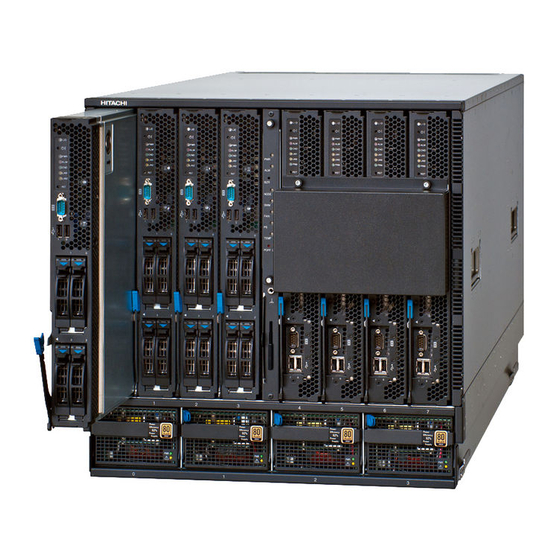
System equipment Names and functions Compute Blade system equipment Front view of A1/A2 chassis... - Page 64 Rear view of A1 chassis Rear view of A2 chassis...
- Page 65 Front view of system configuration Server chassis Front panel Server blade Power supply module Respective types of power supply modules are installed in A1 chassis and A2 chassis. See “Power Supply Module Specifications per module” in the Appendix for details.
- Page 66 Rear view of system configuration A1 chassis Back plane Switch module Switch module Fan module Management module I/O board module I/O board module AC power input module Rear view of system configuration A2 chassis Back plane Switch module Switch module Fan module Management module...
-
Page 67: System Front View
System front view Server Server Server blade [6] blade [4] Server blade [3] blade [1] Server Server Server blade [5] Server blade [2] blade [7] blade [0] Front panel Power supply Power supply Power supply Power supply module slot [0] module slot [1] module slot [2] module slot [3]... - Page 68 SW MOD LED (SWM) Lights solid orange when an error occurs in a switch module or management module. FAN LED (FAN) Lights solid orange when an error occurs in a fan module. PS LED (PS) Lights solid orange when an error occurs in a power supply module. TEMP LED (TEMP) Lights solid orange when the temperature is abnormal in the server chassis.
- Page 69 Standard server blade X55A1/X55A2 Mezzanine card Upper Lower Upper Lower Internal SAS RAID card X55R3/X55S3/X55R4 Mezzanine card Upper Lowe Upper Lowe Upper Lowe...
- Page 70 X55A1/X55A2 X55R3/X55S3/X55R4 Power button Press and hold this button for at least one second to turn on main power to the server blade. If you press and hold this button for 4 seconds or more while the OS is running, it will shut off main power to the server blade without an orderly OS shutdown.
- Page 71 Condition LED (CND) Lights solid green during BMC initialization. Local area network (LAN) 1/2 LED (LAN1) (LAN2) Lights solid orange when a link to the network is established. Blinks orange when the network is running. Hard disk drive (HDD) active LED Blinks green when booting or accessing the HDD.
- Page 72 High-performance server blade (X57A1/X57A2) Mezzanine card Power button Press and hold this button for at least one second to turn on main power to the server blade. If you press and hold this button for 4 seconds or more, it will shut off main power to the server blade without OS shutdown.
- Page 73 Error LED (ALM) Lights solid red when an error occurs. Lights solid red, when timeout of WDT of BMC, a management microcomputer for the server blade, is detected if SC/Agent is installed. To set WDT of BMC, see the Guide for Administrator of ServerConductor/BladeServer Manager system.
-
Page 74: Power Supply Module
Power supply module POWER LED Lights solid green when main power is on. Blinks green when the sub-power is on. FAIL LED Lights solid orange when not working according to specifications due to an error. Blinks orange when the AC input is off. -
Page 75: System Rear View
System rear view Rear view of A1 chassis Switch Switch module slot [1] module slot [0] Management Management Switch module slot [1] module slot [0] Switch module slot [3] module slot [2] Switch Switch module slot [5] module slot [4] module slot [2] module slot [1] module slot [3]... - Page 76 Rear view of A2 chassis Switch Switch module slot [0] module slot [1] Management Management Switch module slot [0] module slot [1] Switch module slot [3] module slot [2] Switch Switch module slot [4] module slot [5] module slot [1] module slot [2] module slot [0] module slot [3]...
- Page 77 Management module Shutdown button (SHDN) Press and hold for 4 or more seconds to shutdown the management module. Keep pressing the button until the power LED blinks or turns off. Location ID LED (LID) Lights solid blue when the management module is located. Power LED (PWR) Lights solid green when this module is in operation.
- Page 78 Switch module 1-Gbps LAN switch module POWER LED (PWR) Turns off when the power fails or no power is supplied. STATUS1 LED (ST1) Indicates the status of the module. Lights solid green during normal operation. Blinks green during power-on diagnosis or software activation. Blinks red when the temperature threshold is exceeded or a warning such as fan failure is detected.
- Page 79 1/10 Gbps LAN switch module POWER LED (PWR) Turns off when power fails or no power is supplied. STATUS1 LED (ST1) Indicates the status of the module. Lights solid green during normal operation. Blinks green during power-on diagnosis or software activation. Blinks red when the temperature threshold is exceeded or a warning such as Fan failure is detected.
- Page 80 LINK LED for XFP Lights solid green when a link is established. Lights solid orange when a failure is detected. TX/RX LED for XFP Lights solid green when a link is established or during communication. 10 Gbps Data Center Bridging (DCB) switch module Location ID LED (LOCID) Lights solid blue while the switch module is located.
- Page 81 Lights solid green when online; blinks green when link is active; blinks green at low speed when online but segmented. Blinks green rapidly when performing diagnostics using inner loopback. Turns off when the signal is not received. 1 Gbps LAN pass-through module POWER LED (PWR) Turns off when the power fails or no power is supplied.
- Page 82 STATUS1 LED Indicates the module status. Lights solid green in normal operation. Blinks green during power-on diagnostics or executing initial settings in the module. Blinks red at warning when the temperature is beyond the threshold while the module is working. Lights solid red when the module has a serious failure causing improper behavior.
- Page 83 Fibre channel (FC) interface connectors: 0 - 5 These connectors are equipped with optical modules: small form-factor pluggable plus (SFP+). Connect a Fibre-channel cable to this optical module. FC port diagnosis LED: orange Shows a diagnosis of a FC port status. Lights solid orange when a signal is received but not on line.
- Page 84 I/O board module Power LED (PWR) Lights solid green when main power is turned on. Attention LED (ATN) Lights solid orange when the I/O board module fails. Attention button (ATN) Used for hot-inserting or hot- removing the I/O board module. Note: This hot-plug function is currently not supported.
-
Page 85: Fan Module
AC power input module With two input connectors With one input connector Fan module ACTIVE LED Lights solid green while the fan is working normally. Lights solid orange when the module is not working due to a failure. -
Page 86: I/O Slot Expansion Unit
I/O slot expansion unit Names and functions Overview of I/O slot expansion unit Front view of I/O slot expansion unit Rear view of I/O slot expansion unit ... - Page 87 Front view of I/O slot expansion unit configuration Power supply module for I/O slot expansion unit Fan module for I/O slot expansion unit Rear view of I/O slot expansion unit configuration I/O module I/O adapter for I/O slot expansion unit...
- Page 88 Detailed front view of the I/O slot expansion unit Power supply module [0] Power supply module [1] Fan module [0] Fan module [3] Fan module [1] Fan module [2] Power button Press and hold this button for at least one second to turn on the I/O module and fan module.
- Page 89 Power supply module for I/O slot expansion unit ACTIVE LED (ACT) Lights solid green when the module is supplying power. Blinks green when the module is in standby mode. Blinks orange when the module is not working properly due to a failure. Blinks orange when temperature exceeds its threshold, or if any fan works improperly.
- Page 90 Details rear view of I/O slot expansion unit I/O adapter slot I/O adapter slot [8] – [15] [0] – [7] I/O module [1] I/O module [0] I/O module C D E Attention button (ATN) Starts the hot insertion and hot removal of the I/O module. Reset button (RST) Resets the I/O module when it is pressed for a second or more and released.
- Page 91 Blinks green when the I/O module with power-on is in the standby mode. Error LED (ALM) Lights solid red when a failure occurs in the I/O module. STATUS LED (STS) Indicates the status of the module. Lights solid green during normal operation. Blinks green during power-on diagnosis or software activation.
- Page 92 I/O adapter for I/O slot expansion unit Attention button (ATN) Starts the hot insertion and hot removal of the I/O adapter. POWER LED (PWR) Blinks green when power to the I/O adapter is turning on or off. Attention LED (ATN) Blinks orange when the I/O adapter is located.
-
Page 94: Connecting The System Equipment And Powering On
Connecting the system equipment and powering on This chapter describes how to install, connect, and turn on or off the power to the system. Install the system ....................44 Connect the system ....................45 Connect the I/O slot expansion unit ..............68 Turning power on or off .................. -
Page 95: Install The System
Install the system This section provides information on how to install the system equipment. WARNING Since the equipment is heavy, be careful when you move it. Handling of this equipment without extra care can injure your arms or back. To relocate or lift heavy loads such as this product, use tools or perform the ... -
Page 96: Connect The System
Connect the system This section describes how to connect the remote console, Universal Serial Bus (USB) cable, and power cable. Connect the remote console The remote console is used as a console for each server blade of the Compute Blade 2000. -
Page 97: Remote Console Application (Reclient)
Remote Console application (reclient) See the Remote Console Application section in the Hitachi Compute Blade 2000 User’s Guide on the Remote Console Application CD attached to the server blade for detailed information, usage, and restrictions on the Remote Console Application (Reclient). - Page 98 Requirements and restrictions Requirements for console terminal Remote Console Application works on console terminals that meet the following requirements. Item Requirements Browser Internet Explorer 6.0 or later *1 *2 Java VM ORACLE Java Runtime Environment version 6 or later *2 *3 *4 OS*5 Windows Server 2012 R2 Standard Windows Server 2012 R2 Datacenter...
- Page 99 Requirements for server display settings Remote console application (Java application) supports the following resolutions and number of color bits. Server OS Resolutions Color bits Windows 640 x 480 (VGA mode) 8 bits 800 x 600 16 bits 32 bits 1024 x 768 (recommended) 16 bits (recommended) 32 bits...
- Page 100 The Power ON, Force power OFF, Reset, and NMI operations are disabled, but no message is shown. With an LP-mode OS, operate the power of the server blade from the server blade Web console. See Chapter 5: Server Blade Setup. Java Runtime Environment (JRE) version 7 update25 or higher ...
-
Page 101
2. Click Add. 3. Enter “https://
” and click OK. - Page 102 4. Check that the IP address is shown in the Exception Site List and click OK. (b) Use Java Runtime Environment (JRE) version 7 update 21 or lower Use JRE version before the security policy is changed. When enabling the remote console connection via SSL/TLS, use JRE7u2 or higher.
- Page 103 (c) Set the security level to Medium Start Java Control Panel, and move the security level slider to Medium.
- Page 104 Certificate revocation check Remote console application certificates with BMC 07-14/06-27 are the ones signed by the trusted certificate authority. Check “Do not check (not recommended)” under “Perform certificate revocation checks on” on the Java Control Panel. If not, startup may take longer or a warning message may appear showing the invalid certificate.
- Page 105 Starting Remote Console Application Start a client browser and connect it to the Server Blade web console to display the login page. Click Launch Remote Console on the login page. The Remote Console Application (Java application) will start. If the following dialog box appears, click Yes.
- Page 106 If the following dialog box appears, click Run. When Remote Console Application is started, a login dialog appears. Enter the User ID and Password. Click Connect.
- Page 107 If user authentication succeeds, a window appears and the server blade VGA screen is displayed. If you already logged in to the Server Blade Web Console, use Launch Remote Console on the left side of the page. Terminating Remote Console Application To terminate the Remote Console Application, select [Exit] on the menu bar, and click [Exit] on the submenu which appears by clicking [Exit] on the menu bar.
- Page 108 Functions of Window This section describes the functions of the Remote Console Application window. Part Function The title bar shows the IP address, power status, and Location Title bar ID Lamp (LID) light emitting diode (LED) status of the server blade.
- Page 109 In full screen mode, you can use the bar at the top of the screen, which appears when the mouse cursor is moved to the top of the screen, to operate the Remote Console Application. Part Function Pin button The button is used to have the bar always displayed. Menu button The button is used to display the menu that runs the functions of Remote Console.
- Page 110 Menu items and functions The following table lists the menu items and their functions. Menu Item Function Power and Power ON Power on the server blade. Reset Forced power Power off the server blade. Reset Reset the server blade. Generate NMI to the server blade. Video Refresh screen Redraw the remote screen to show the latest server blade video...
- Page 111 Shortcut keys Some functions of Remote Console Application can be executed using the keyboard. Shortcut Key Function Alt+Z Press the left Alt key. The key is kept pressed until this shortcut key is used again. Alt+M Press the right Alt key. The key is kept pressed until this shortcut key is used again.
- Page 112 When the Remote Console does not work properly, terminate it and then restart it. If re-startup does not work, see the Compute Blade 2000 Remote Console Application Guide in the remote console application CD that is attached to the system equipment.
-
Page 113: Connect The Usb Cable To The Server Blade
Connect the USB cable to the server blade One server blade is equipped with two USB ports. USB port USB DVD drive USB floppy disk drive (sold as an extra (sold as an extra item.) item.) A USB device such as DVD or floppy disk drive (FDD) drive can be connected to the USB connector. -
Page 114: Connect The Power Cables
Connect the power cables WARNING Do not connect multiple power cables to a single electrical outlet. Overheating the power cables or outlet could cause a fire and trip the circuit breaker, which affects other devices on the same circuit. When unplugging a power connecter, wait 10 or more seconds before reconnecting the power cable because the system equipment may not boot. - Page 115 A1 chassis 1+1 power module redundant configuration Connect power cables to each outlet from the distribution panel #A. Power cable for AC200 V 200 VAC - 240 VAC NEMA L6-30R IEC60309-32 Distribution panel #A 1+1 AC power module redundant configuration ...
- Page 116 2+1 power module redundant configuration Connect power cables to each outlet from the distribution panel #A. Power cable for AC200 V 200 VAC – 240 VAC NEMA L6-30R IEC60309-32 Distribution panel #A 2+2 AC power module redundant configuration Connect power cables to each outlet from the distribution panel #A or # B.
- Page 117 A2 chassis 1+1 DC power module redundant configuration (up to 3.6 kWdc) Connect power cables to each outlet from the distribution panel #A. 200 VAC – 240 VAC FFB 30 A up to 3.6 kWdc up to 10 A 12 –...
- Page 118 1+1 AC power module redundant configuration (up to 3.6 kWdc) Connect power cables to each outlet from the distribution panel #A or #B. Line A Line B 200 VAC – 240 VAC 200 VAC – 240 VAC FFB 30 A up to 3.6 kWdc Distribution up to 10 A...
-
Page 119: Connect The I/O Slot Expansion Unit
Connect the I/O slot expansion unit This section describes how to connect power cables to the I/O slot expansion unit. Connect the power cables WARNING Do not connect multiple power cables to a single electrical outlet. Overheating of the power cables or outlet could cause a fire and trip the circuit breaker, which affects other devices on the same circuit. - Page 120 1 + 1 DC Input redundancy configuration Connect the power cable to the power distribution unit (PDU), and connect the PDU to the socket outlet through the distribution panel #A. Power cable for 200 VAC 200 VAC – 240 VAC Distribution panel #A 15A x4 FFB 30 A...
-
Page 121: Turn The Power On Or Off
Turning power on or off This section describes how to turn on and off power to the system equipment. NOTICE Follow the prescribed procedure for power operation. Powering on or off not according to the prescribed procedure can cause equipment failure. After turning off or on the power to the system equipment, wait at least 10 seconds before turning on or off the power again. -
Page 122: Turn Off The Power
Turn off power Some peripheral devices may need to be turned off before the system equipment is turned off. For details, see the manuals of the peripheral devices. Execute shutdown for each server blade from the OS. When power is turned off, the POWER LED on the server blade lights solid orange. ... -
Page 124: Adding Optional Components
Adding optional components This chapter provides information about installing optional components. Mounting internal optional components ..............74... -
Page 125: Mount Internal Optional Components
Mounting internal optional components Optional internal components can be mounted into the system equipment. Only maintenance personnel are permitted to add each optional component to the system. Contact the reseller from which you have purchased the equipment, or call maintenance personnel. CAUTION Adding or replacing optional components inside the system equipment must be performed by maintenance personnel. -
Page 126: Server Blade Setup
Server blade setup This chapter describes the server blade setup. Standard server blade settings (X55A1/X55A2/X55R3/X55S3 models) ....76 Standard server blade setup menu (X55A1/X55A92 Models) ......127 Standard server blade setup menu (X55R3/X55S3/55R4 models) ....141 Remote CD/DVD boot procedure ................ 158 Hardware memory dump .................. -
Page 127: Standard Server Blade Settings (X55A1/X55A2/X55R3/X55S3/X55R4 Models)
Standard server blade settings (X55A1/X55A2/X55R3/X55S3/X55R4 models) This section describes the standard server blade setup with the Web console. Standard server blade setup menu (X55A1/X55A2 models) Standard server blade setup menu (X55R3/X55S3/55R4 models) for the basic input/output system (BIOS) menu. Initial settings with server blade web console A server blade can be managed remotely by using the server blade web console. -
Page 128
Login Start the client web browser. Enter http://
: to the URL address field. You can omit the port number only when the port number is “80”. To find the server blade IP address, see “LC Command” in Chapter 6. Ex. - Page 129 If a user account is set in the server blade different from the above, you cannot log in using the method mentioned above. Hitachi Data Systems recommends selecting a user account name different from the default setting value for security purposes.
- Page 130 When the login is successful, the server information menu screen is displayed. You can select menu items using the upper tabs and tree menu on the left. When a menu item is selected, the screen for displaying or changing the corresponding settings is displayed.
- Page 131 User account configuration Configure user accounts to operate the server blade remotely. Privileges to operate the server blade, validity, username, and password can be configured for each user account. Select the Server Settings tab and then select User Accounts in the tree menu to display the following screen.
- Page 132 BMC: 04-71 or 06-01 with a high-performance server blade, X57A1 or X57A2 model For information about the remote console (Reclient), see the Hitachi Compute Blade 2000 Remote Console Application User’s Guide contained in the remote console application CD that came with the system equipment.
- Page 133 (2) Initial setting of user accounts The following table shows the initial setting of user accounts. User Password Role Description name user01 pass01 Login User as the server blade administrator. The role of the Administrator user cannot be changed. user02 pass02 None Ordinary users...
- Page 134 Item Description Username Enter user account name: up to 32characters Password Enter password: up to 32 characters. Password (Confirm) Re-enter the password for confirmation. Role Login Check the roles to assign to the user account. Administrator Server Operation User Account Management Service Settings Remote Console...
- Page 135 When you click Modify, the following confirmation screen is displayed. Item Description Cancels the edited settings and returns to Edit User Back Account screen. Confirm Allows the edited settings to become effective.
- Page 136 LPAR manager boot settings Configure the LPAR manager boot settings. Select Server Operation in the upper tabs and then select LP Setup in the tree menu on the left to display the following screen. If you do not use LPAR manager, set OS mode to Basic mode, which is the default setting.
- Page 137 Validates the edited settings and moves to the Modify confirmation screen. For the remote console (Reclient), see the Hitachi Compute Blade 2000 Remote Console Application User’s Guide contained in the remote console application CD that came with the system equipment.
- Page 138 BMC time settings Set the time of the server blade BMC (Baseboard Management Controller). Select Server Settings in the upper tabs and then select BMC Time in the tree menu on the left to display the following screen. BMC time is used for (1) time stamp of error logs, and (2) the schedule operations linked with ServerConductor.
- Page 139 Item Description The BMC time is independent of the OS time and is determined by a clock that has an error by ± 4 minutes per month. Check the time on the BMC Time Screen, and adjust the time if the error is large. (3) LP mode: LPAR manager sets BMC time to “LP system time”.
- Page 140 Details for setting the timezone of the LP system time are described in Logical partitioning manager-LPAR manager Screen Operations- Summary of LPAR manager Screens-Date and Time. If Use NTP or Use the NTP server of the Management Modules is selected in #2 Time Synchronization Method, the time synchronization between the BMC time and the OS time by the SC agent is disabled.
-
Page 141: Server Blade Web Console Function
Server blade web console function This section describes the functions of the server blade web console. (1) List of user accounts screen The following table shows functions provided by the server blade web console. Menu Function Server Operation tab Server Information Shows the server blade information Power and LEDs Controls the power status and reset operation. - Page 142 Menu Function settings. Backup Server Backups the server blade settings except for Management Settings EFI and LPAR manager settings. Restore Server Restores the server blade settings except for Management Settings EFI and LPAR manager settings. Restart BMC Restarts BMC. FPGA ROM Management Updates field programmable gate array (FPGA) Read Only Memory (ROM).
- Page 143 Available operation with each role Menu Admin- Server Service User Account istrator Operation Settings Management Server Settings tab Language Information Information Settings display display only. only Asset Information Network Settings Service Settings Security and Service Settings Your own Your own Settings of User Accounts account...
- Page 144 The Remote Console, Remote Media, and SMASH CLP roles are not related to the operations of the server blade Web console. With X57A1/X57A2 model, you can operate all menus in the server configuration and reduction settings using the Administrator role.
-
Page 145: Server Operation Tab
Server Operation tab Using the Server Operation tab, you can display the information of the server blade, control the power status, and configure the boot settings of the server blade. Server information The following screen shows the server blade information. Item Description Refresh... - Page 146 Item Description Chassis Information Slot Number shows the slot number of the slot where the server blade is inserted. Chassis ID shows the chassis ID set in the management module. Power and LEDs This screen shows the power and LED status of a server blade. You can control the power state and reset the server blade on this screen.
- Page 147 Item Description blade, Spare Channel Mode cannot be used. Hardware Memory Dump Performs hardware memory dump of the server blade. LID On Turns on LID (Location ID Lamp). LID Off Turns off LID (Location ID Lamp). LED Status Shows the state of the LEDs on the front panel of the server blade.
- Page 148 EFI setup You can configure the main settings of EFI on the following screen. Item Description Refresh Reloads the information. SMT (Simultaneous Multi- Disables or enables the SMT function of Intel Threading) CPU. Disable / Enable (Default) Turbo Mode Disables or enables the Turbo mode of Intel CPU.
- Page 149 Item Description Socket Interleave (*2) Sets the shared memory configuration of the memory system. Non-NUMA NUMA (NUMA: Non-Uniform Memory Access) VMware Host Memory Enables or Disables the error memory report Retirement (*3) function for VMware. Disable (Default) / Enable Option ROM Execution Sets execution mode of the expansion ROM of Policy the mezzanine cards and the PCI-Express...
- Page 150 Item Description (*6) (PCIe) is in failure: PCIe Error Isolation: EFI isolates a failed PCI Express. Legacy (Default): EFI does not isolate a failed PCI Express. OS AER: OS performs Advanced Error Reporting (AER). Available only for OS that support AER. PCI Error Isolation - Disables or enables PCI Express Error On-board NIC (*7)
- Page 151 (*8) The UEFI boot can be set only when Windows Server 2012 or later is booted from the Hitachi 8 Gb fibre channel (PCI card/expansion card) or Hitachi 16 Gb fibre channel (PCI card). For Hitachi 16 Gb fibre channel, firmware version 11-40/12-40 or higher is required.
- Page 152 LP setup You can enable and disable the LPAR manager boot and set the LPAR manager firmware to be used for the LPAR MANAGER boot on this screen. See LPAR manager boot settings in “Initial Settings with Server Blade Web Console”. ...
- Page 153 Item Description Refresh Reloads the information. CPU Information: Shows the types of CPUs: information on the last CPU0 Brand String EFI boot. CPU1 Brand String Current Reduction Status Shows the current reduction status of CPU/DIMM. Configured: not deconfigured. Deconfigured: deconfigured as planned. Absent: not installed.
-
Page 154: Server Settings Tab
Server Settings tab You can use the Server Settings tab to configure the functions to manage the server blade. Language settings You can set the language used on the server blade web console on the following screen. Item Description Refresh Reloads the information. - Page 155 Asset information You can set the asset information on the server blade on this screen. Item Description Refresh Reloads the information. Server Name Sets the server blade name. The server name is shown in the Server name field at the left top of the screen and Server Information screen in the Server Operation tab.
-
Page 156: Network Settings
Network settings This screen shows the management network settings of the server blade. You can set restrictions on the IP address of the network device that can be connected to the server blade. You can specify up to four IP addresses to allow connection to the server blade. -
Page 157: Service Settings
Service settings You can enable or disable the services provided by the server blade and set the port numbers to be used by the services on this screen. Item Description Refresh Reloads the information. Enables or disables the OS console via SSH. OS Console (SSH) Shows the port number used by the OS console via SSH. - Page 158 To power on or off a server blade from SC/Blade Server Manager, register the server chassis as a target on SC/Blade Server Manager before setting IPMI over the LAN. Security and Service Settings You can enable or disable security and services provided by server blades and set port numbers for the services.
-
Page 159: User Accounts
Item Description HTTPS; selects TLS version used for HTTPS connection. Shows the HTTP port and HTTPS port used by the server blade Web console. Enables/disables IPMI over LAN; permits or not access over LAN v1.5 and null account; selects suite IPMI over LAN privilege levels.* Shows the port number used by the IPMI Over LAN. - Page 160 SSH Server You can set the authentication method of SSH and check the fingerprint of the host keys on this screen. Item Description Refresh Reloads the information. Displays the fingerprint of host public keys that Host Key Fingerprints are used in the server blade SSH server. SSH Host Keys * Updates SSH host keys.
- Page 161 SSL Server You can set up the SSL server certificate on this screen. You can display the information of the server certificate used by the server blade, create a self-signed server certificate, create a certificate signing request (CSR), import a server certificate, and download the server certificate.
- Page 162 Item Description Refresh Reloads the information Server Certificate Displays the information of the server certificate used by the Information server blade. The following information is displayed: Version Serial Number Public Key Algorithm and Key Size Validity (Not Before) Validity (Not After) Issuer (Only Common Name (CN) is displayed.) Subject SHA1 Fingerprint...
- Page 163 Item Description Unstructured Name and Challenge Password can be omitted. The characters that can be used in those items are the same as specified in #3. Reset Cancels the edited settings in #6. Create and Creates a CSR using the information specified in #6. When the Download CSR button is pressed, the confirmation screen is displayed.
- Page 164 DNS Client You can set the IP addresses of DNS servers on the following screen to have the server blade do name resolution using DNS. Up to 3 IP addresses can be specified. Item Description Refresh Reloads the information. Sets the IP addresses of DNS servers.
-
Page 165: Ipmi Over Lan
IPMI Over LAN You can set IPMI Over LAN to user accounts. Item Description Refresh Reloads the user account information. Select Selects user accounts. User ID ID for the user account Status Shows Enable or Disable the user account. User name User account name Privilege Level... - Page 166 When you click Edit, the Edit IPMI Over LAN User Account screen appears. Item Description User ID ID for the user account Status Shows Enable or Disable the user account. User account name consists of up to 16 User name*1 alphanumerics.
- Page 167 When you click Modify on the Edit IPMI Over LAN User Account screen, the following screen appears. When clicking Back, you return to the Edit IPMI Over LAN User Account screen without saving the edits. When clicking Confirm, you return to the List of IPMI Over LAN User Accounts screen while saving the edits.
- Page 168 LDAP You can set user authentication with the LDAP. See “LDAP Server Linkage” in Chapter 13 for more information. Item Description Refresh Reloads the information. Specifies a user authentication method. Do not use LDAP user authentication: Authenticates a user with user accounts registered in the server blade.
- Page 169 Item Description Enables a TLS version for connection to the TLS Version(*2) LDAP server. Specifies a DN used for binding to the LDAP server: up to 256 characters. Bind DN If nothing is typed in this field, anonymous bind is used. Specifies a password used for binding to the LDAP server: up to 32 characters.
- Page 170 Syslog Transfer You can set Syslog transfer on the following screen. See “Syslog Transfer” in Chapter 13 for details about the features. Item Description Enable/Disable Enables or disables Syslog transfer. Syslog transfer Specifies a syslog server using IP address in Syslog Server XXX.XXX.XXX.XXX, or FQDN using up to 127 characters.
-
Page 171: Maintenance Tab
Maintenance tab Using the Maintenance tab, you can update the firmware, backup and restore the data managed on the firmware, and restart BMC. EFI Firmware Management Only maintenance personnel can use this menu. BMC Firmware Management You can update and switch BMC firmware on this screen. The server blade has two banks (Bank0 and Bank1) of storage area for the BMC firmware. -
Page 172: Restore System Settings
Item Description on this bank. Remote Console Firmware: the version of the remote console function. Logical SVP: the version of the logical SVP function. Bank1 Shows the Bank1 information. Specifies the image file of BMC firmware to be BMC Firmware Image File uploaded. - Page 173 Cancel PCI Express Deconfiguration This screen shows the current deconfiguration state of PCI Express. You can cancel PCI Express deconfiguration on this screen to make the deconfigured PCI Express devices enabled again. Item Description Refresh Reloads the information. Shows the current deconfiguration state of PCI Express.
-
Page 174: Logs Tab
Logs tab Using the Logs tab, you can download the logs collected by BMC, the blade management micro controller. Download Logs You can download the log files corrected by the BMC on this screen. Item Description Download Logs Downloads the log files collected by BMC. The log file contains the following logs. - Page 175 See “OS Console (Serial console redirection)” in Chapter 13 for information about the OS console. The OS console can be used by connecting to the BMC IP address of the server blade via Telnet or SSH. See “BMC Environment Setting Utility” – ...
- Page 176 The confirmation screen is as follows. Item Description Cancels the operation and returns to the Back previous screen. Confirm Clears the operation logs. VFP (Virtual Front Panel) Log Function The VFP log function of a server blade captures the liquid crystal display (LCD) outputs of EFI and records them to the internal storage.
- Page 177 Example of VFP logs Recovery procedure for server blade web console connection: If you cannot connect to the server blade web console or the server blade web console does not respond for more than 1 minute when you click a menu item or a button, follow the recovery procedures described below.
-
Page 178: Standard Server Blade Setup Menu (X55A1/X55A2 Models)
Standard server blade setup menu (X55A1/X55A2 models) EFI Setup Screen By entering the EFI Setup screen while the server blade is booting, you can halt the boot process and check or change the settings. With the EFI startup screen open, press the F2 key to display the EFI Setup screen. The EFI Setup screen has six setup menus: Main, Advanced, Chipset, iSCSI, Boot, Security, and Save &... -
Page 179: Main Menu
Main menu Figure 5-1 Main menu On the Main menu, you can check the following items: EFI version: (1) Installed memory: (2) Server blade system time: (3) Note: The keys used for operations in the EFI Setup menus are shown on the right side of the screen. - Page 180 Checking the installed memory After increasing or replacing memory, you can check the amount of installed memory from the following item. Note that the displayed size is the total memory.* In this example, 6144 MB of memory is installed. *Note that when memory mirroring mode is enabled, the displayed size is one half of the total installed memory.
-
Page 181: Advanced Menu
Advanced menu On the Advanced menu, you can enable or disable the PXE booting option. Standard Server Blade Setup Menu (X55R3/X55S3/X55R4 Models) Figure 5-2: Advanced Menu... - Page 182 To enable PXE booting, move the cursor to Launch PXE OpROM and press Enter. Figure 5-3: Setting PXE Enabled The screen appears as shown in Figure 5-3. To specify Enabled, move the cursor to Enabled and press Enter. Next, enable PXE booting for LAN1 in the same manner. Figure 5-4: Setting LAN1 PXE Enabled...
- Page 183 To enable PXE booting for LAN2, perform the setting in the same manner. You can enable PXE for LAN1 and LAN2 respectively or simultaneously. Figure 5-5: Setting LAN2 PXE Enabled After changing settings, make sure to select Save Changes and Reset or Save Changes on the Save &...
-
Page 184: Chipset Menu
Chipset menu On the Chipset menu, you can check memory-related and Wake On Lan settings. Figure 5-6: Chipset Menu (1) Checking the Memory Mode and NUMA Settings To check the Memory Mode and NUMA settings, select North Bridge on Figure 5-6 Chipset menu to show the following sub-menu. - Page 185 EFI setup in Server Blade Web Console Function for details about setting the memory mode on the server blade web console. On the North Bridge sub-menu, you can check the Memory Mode and NUMA settings, but you must not attempt to change the settings. Change the Memory Mode and NUMA settings, if necessary, only from the server blade Web console.
-
Page 186: Iscsi Menu
iSCSI menu On the iSCSI menu, you can check the internet small computer system interface (iSCSI) settings. Figure 5-9: iSCSI Selection Menu... -
Page 187: Boot Menu
Boot menu On the Boot menu, you can set the boot paths. Figure 5-10: Boot Menu EFI searches connection paths to peripheral devices in the order shown in the following table, and recognizes I/O devices at server blade startup. In Symmetric Multiprocessing (SMP) configuration, I/O devices are recognized in ascending order of server blade number. - Page 188 About Boot Paths (Legacy Boot and EFI Boot) Boot paths are categorized into two boot modes in the Compute Blade 2000. The implemented boot processing depends on which mode you select. The two Compute Blade 2000 boot modes are: ...
- Page 189 Selecting PXE booting PXE booting can be specified in the boot path if Enabled is set for Launch PXE OpROM on the Advanced menu. To specify PXE booting, set Boot Option #1 as follows: Figure 5-11: Setting the PXE Boot Path Figure 5-12: Screen with PXE Boot Path Specified After changing the setting, remember to select Save Changes and Reset or Save Changes on the...
-
Page 190: Security Menu
Security menu The Security menu is for setting the administrator or user password. Figure 5-13: Security menu You need to input a password, which you have set, at the timing shown in the following table. Administrator User Request for password authentication password password While a server blade is being booted *1... -
Page 191: Save & Exit Menu
Save & Exit menu Use the Save & Exit menu to save changes or to restore changed settings to the Defaults. Figure 5-14: Save & Exit menu Each item is described in the following table. Item Processing Save Changes and Exit Saves changes and exits the Setup utility. -
Page 192: Standard Server Blade Setup Menu (X55R3/X55S3/X55R4 Models)
Standard server blade setup menu (X55R3/X55S3/55R4 models) EFI setup screen By entering the EFI setup screen while the server blade is booting, you can halt the boot process and check or change the settings. With the EFI startup screen open, press one of the following keys to display the EFI Setup screen. -
Page 193: Main Menu
Main menu Figure 5-15 Main menu On the Main menu, you can check the following items: EFI version: (1) Installed memory: (2) Server blade system time: (3) Note: The keys used for operations in the EFI Setup menus are shown on the right side of the screen. - Page 194 Checking the installed memory After increasing or replacing memory, you can check the amount of installed memory from the following item. Note that the displayed size is the total memory.* In this example, 32 GB of memory is installed. *When memory mirroring mode is enabled, the displayed size is one half of the total installed memory.
-
Page 195: Advanced Menu
Advanced menu On the Advanced menu, you can enable or disable the PXE booting option, show iSCSI settings, and set Trusted Platform Module (TPM) if TPM is installed. For the X55R4 model, Launch PXE OpROM and Launch storage OpROM are not shown;... - Page 196 (1) Enabling/Disabling PXE booting To enable PXE booting, move the cursor to Launch PXE OpROM and press Enter. Figure 5-18: Setting PXE enabled The screen appears as in Figure 5-18. To specify Enabled, move the cursor to Enabled and press Enter. Next, enable PXE booting for LAN1 in the same manner.
- Page 197 To enable PXE booting for LAN2, perform the setting in the same manner. You can enable PXE for LAN1 and LAN2 respectively, or simultaneously. Figure 5-20: Setting LAN2 PXE enabled (2) Viewing iSCSI To show iSCSI settings, place the cursor on iSCSI and press Enter. Figure 5-21 iSCSI setting to view or not...
- Page 198 The following screen shows the iSCSI setting. Figure 5-22: iSCSI setting shown (3) TPM settings To set TPM, place the cursor on Trusted Computing and press Enter to show the TPM setting screen. Figure 5-23 TPM to set or not...
- Page 199 Do not disable TPM SUPPORT. If you do, BitLocker may not be installed. Just view other items and do not change their values. Figure 5-24: TPM to set On Windows Server 2012 installed from EFI boot, do not execute BitLocker drive encryption using TPM due to it not being supported.
- Page 200 Physical presence request When you operate TPM using a program on the OS, the following Physical presence request may be displayed while booting the server blade next time. It requires user intervention to distinguish the TPM operation from that by a malicious program. Follow the directions shown on the screen.
-
Page 201: Chipset Menu
Chipset menu On the Chipset menu, you can check memory-related and Wake On Lan settings. Figure 5-26: Chipset menu (1) Checking the memory mode and NUMA settings To check the Memory Mode and NUMA settings, select North Bridge on the Chipset menu. - Page 202 See the BMC manual about setting the memory mode on the server blade Web console. On the North Bridge sub-menu, you can check the Memory Mode and NUMA settings, but you must not attempt to change the settings. Change the Memory Mode and NUMA settings, if necessary, only from the server blade web console.
-
Page 203: Boot Menu
About boot paths (legacy boot and EFI boot) Boot paths are categorized into two boot modes in the Compute Blade 2000. The implemented boot processing depends on which mode you select. The two Compute Blade 2000 boot modes are: ... - Page 204 Selecting PXE booting PXE booting can be specified in the boot path if Enabled is set for Launch PXE OpROM on the Advanced menu or on the Server Operation > EFI Setup of the server blade Web console. See Standard server blade settings (X55A1/X55A2/X55R3/X55S3/X55R4 models) for details of the server blade Web...
- Page 205 Figure 5-31: PXE boot path specified (Example of Legacy boot) After changing the setting, remember to select Save Changes and Reset or Save Changes on the Save & Exit menu.
- Page 206 Reset boot option When you reboot a server blade with Reset Boot Option Enabled, Boot Option Priorities is initialized. Execute the following to initialize Boot Option Priorities. Remove the boot device and Built-in EFI shell to delete the boot option ...
-
Page 207: Security Menu
Security menu The Security menu is for setting the administrator or user password. Figure 5-32: Security menu You need to enter a password, which you have set, according to the table below. Administrator User Request for password authentication password password While a server blade is being booted ... -
Page 208: Save & Exit Menu
Save & Exit menu Use the Save & Exit menu to save changes or to restore changed settings to the defaults. Figure 5-33: Save & Exit menu Each item is described in the table below. Item Processing Save Changes and Exit Saves changes and exits the Setup utility. -
Page 209: Remote Cd/Dvd Boot Procedure
Remote CD/DVD boot procedure To boot the server blade from the remote CD/DVD or to install the OS using the remote CD/DVD function, follow the procedure mentioned below. Steps may be different depending on your remote console application. Remote Console Application (Reclient) Insert the CD/DVD media into the console terminal’s CD/DVD drive. - Page 210 Select the console terminal’s CD/DVD drive, and then click OK. Steps 1 to 3 must be performed before powering on or resetting the server blade; otherwise, the server blade will not recognize the remote CD/DVD. If you want to install an OS or perform some other task using a remote FD, complete steps 1 to 3 and then select the Remote FD menu and Start FD.
- Page 211 Select the Boot menu using the arrow keys. Make sure that HITACHI Remote FD is set in Boot Option #1 and HITACHI Remote CD/DVD is set in Boot Option #2, as shown in the following figure. Depending on the types of devices installed in or connected to the server blade, the display may differ from the following screen.
-
Page 212: Remote Console Application (Java Application)
If you made no changes, select Save & Exit menu -- Discard Changes and Exit to restart the server blade. If you changed any settings, select Save & Exit menu -- Save Changes and Exit to restart the server blade. After the server blade has restarted, the system will automatically start booting from the remote CD/DVD. - Page 213 Select a CD/DVD drive, then click OK. Steps 1 to 3 must be performed before powering on or resetting the server blade; otherwise, the server blade will not recognize the remote CD/DVD. If you want to install an OS or perform some other task using a remote FD, complete steps 1 to 3 and then choose the Remote FD menu and Start FD.
- Page 214 Select the Boot menu using the arrow keys. Make sure that HITACHI Remote FD is set in Boot Option #1, and HITACHI Remote CD/DVD is set in Boot Option #2, as shown in the following figure. Depending on the types of devices installed in or connected to the server blade, the display may differ from the screenshot below.
- Page 215 console terminal after installation. If HITACHI Remote CD/DVD or HITACHI Remote FD is not listed in the boot options, change the settings as follows. Use of a remote CD/DVD is assumed here: On the Boot menu, select CD/DVD ROM Driver BBS Priorities.
- Page 216 After enabling HITACHI Remote CD/DVD, press ESC to return to the Boot menu. On the Boot menu, set HITACHI Remote CD/DVD in Boot Option #2. To boot from a remote FD, select Floppy Driver BBS Priorities on the Boot menu...
- Page 217 After installation is completed, remove the CD/DVD media from the console terminal’s CD/DVD drive. Then, choose the Remote CD/DVD on the toolbar of the Remote Console Application and End CD/DVD. If you use a remote FD, remove the floppy disk from the console terminal’s floppy drive, and then choose the Remote FD on the toolbar and End FD.
-
Page 218: Hardware Memory Dump
VMware startup, when Loading VMware xxxx is displayed or earlier. When tboot package is installed, the feature will not work. Change the setting value to the one described in the Hitachi Compute Blade 2000 Software Guide. -
Page 219: How To Set Hardware Memory Dump
Recommended partition size is about 102% of the physical memory size installed. (*) For Hitachi 16 Gb fibre channel, the following EFI firmware version is required. Version 11-40/12-40 or higher for standard server blade model, X55R4 Version 07-65/08-65 or higher for high-performance server blade model, X57A2... - Page 220 (2) Format the partition with FAT32. mkdosfs –n LABEL –F 32 /dev/sdx1 LABEL: any volume label (up to 11 American Standard Code for Information Interchange (ASCII) characters) The size of disk partitions available is 1.9 TB or less due to the restriction on the FAT32 supported by the EFI firmware.
- Page 221 HBA BIOS is Enabled. See “Procedure to set a HBA-BIOS to Enable” in the Hitachi Gigagbit Fibre Channel Adapter User’s Guide (BIOS/EFI Edition) for detailed procedures . The LU with a dump partition is registered in Boot Priority.
- Page 222 Specify the post process of the hardware memory dump. Select post process and specify a setting suitable for your environment. Spin Loop: Halts after the dump. Reset: Resets automatically and reboots the server blade after the dump. Save the settings and reboot the server blade. To check if the dump partition is properly identified: Select hardware memory dump Settings under the Advanced tab in the EFI setup menu after rebooting the server blade.
-
Page 223: How To Start Hardware Memory Dump
How to start hardware memory dump Hardware memory dump is performed in the Power and LEDs screen under the server operation tab of the server blade web console. In the Power and LEDs screen, click Hardware Memory Dump. In the Power and LEDs (Confirm) screen, click Confirm. Hardware memory dump will start. - Page 224 This operation only gives a command to start hardware memory dump. Then the server blade Web console responds and returns to the Power and LEDs screen before the dump is complete. To check the dump progress, use the OS console ...
-
Page 225: Where Hardware Memory Dump Is Stored
Where hardware memory dump is stored Hardware memory dump data will be stored as a file in the directory on the dump partition. Directory structure Content /HDUMP_YYMMDD_ register.dat Processor Registers hhmm/ pci.dat PCI Config Header manifest.dat Memory Manifest memory_[1 page address].dat (*) Memory Data (*) Address in hex;... -
Page 226: Megaraid Webbios
MegaRAID WebBIOS The system equipment with serial attached SCSI (SAS) internal RAID board: GVX- CA2SRD2X1/GV-CA2SRD2X1-Y can set a disk array using the MegaRAID WebBIOS utility. Under normal operation, you do not need to change the settings. Setting is required only if you need to change the system configuration, for example, when you have changed hard disks. -
Page 227: Sas Raid Controller
SAS RAID controller The following three types of SAS RAID controllers can be installed in the system unit. MegaRAID SAS 1078 (model: GVX-CA2SRD2X1) MegaRAID SAS 2108 (model: GVX-CA2SRD4X1) MegaRAID SAS 2208 (CB2000 standard server blade: X55R3 model) This section describes MegaRAID WebBIOS per SAS RAID controller type. -
Page 228: Megaraid Sas 1078
MegaRAID SAS 1078 Starting and ending MegaRAID WebBIOS Use the following procedure to start the MegaRAID WebBIOS. Turn on the power supply to the system equipment. When the following screen appears, press and hold the Ctrl key and press the H key. - Page 229 Press the Ctrl key once. If you do not press the Ctrl key, your keyboard and mouse Note may not operate properly. If the keyboard or mouse is not available when you operate MegaRAID WebBIOS, press the Ctrl key once. Press Enter once.
- Page 230 Use the following procedure to end the MegaRAID WebBIOS. From the main menu, click Exit. The exit confirmation screen appears. When you want to return to the main menu, click Click Yes. Clicking No returns you to the main menu.
- Page 231 Keyboard > (Ctrl+Alt+Del) in the toolbar or press the Alt+L keys to restart the system equipment. For the remote console (Reclient), see the Hitachi Compute Blade 2000 Remote Console Application User’s Guide contained in the remote console application CD attached to the system equipment.
- Page 232 Operation for MegaRAID WebBIOS For MegaRAID WebBIOS, you can set individual items by using the following keys. Connect a mouse to the remote console before starting MegaRAID WebBIOS. Key/mouse Operation Mouse Moves the mouse cursor. Mouse - left button - Selects an item that the mouse cursor is placed on.
- Page 233 Screen composition for MegaRAID WebBIOS The main menu of the MegaRAID WebBIOS utility includes the Menu Icon, which is not used in operation with the keyboard. Operation in MegaRAID WebBIOS setting/disk array configuration When operating MegaRAID WebBIOS only with the keyboard, replace the mouse with the keyboard as follows: Click (an object).
- Page 234 Configuration of MegaRAID WebBIOS The MegaRAID WebBIOS is configured as shown below. [Ctrl] + [H] keys MegaRAID WebBIOS Starts. Adapter Selection Main menu Controller Selection Controller Properties Scan Devices Virtual Drives Drives Configuration Wizard Physical View/Logical View Events MegaRAID WebBIOS ends. Adapter Selection is displayed on the Controller Selection window.
- Page 235 Screen configuration of MegaRAID WebBIOS The MegaRAID WebBIOS screen configuration is shown below. Menu icon The following icons are available. Icon at the upper left Operation from an icon click on the screen Return to the main menu. Return to the previous screen End the utility.
- Page 236 Click a hard disk from disks displayed in Logical View or Physical View. The same screen is displayed as when you select Virtual Drives > Properties from the menu. Select a disk array from disks displayed in Logical View. The same screen is displayed as when you select Drives > Properties from the menu.
- Page 237 Main menu Start MegaRAID WebBIOS. The following main menu appears. Menu Content Setting/display value Controller Selection Selecting the disk array controller to be operated Controller Viewing and setting the hardware Controller properties: menu for Properties information on the disk array setting the disk array controller board.
- Page 238 Controller properties: menu for setting the disk array controller board You can display and set the hardware information about the disk array controller board. Select Controller Properties from the main menu, and the following screen appears. Display item What is displayed Serial Number Serial number SubVendorID...
- Page 239 Properties: Controller properties submenu 1 Click Next in the Controller Properties screen, and the following screen appears. Display item Display/content Setting/display value ** A Battery Backup Battery backup unit mount status. None B Coercion Mode *1 Setting the capacity control for the [None (using the entire capacity)] / physical hard disk used for disk 128 MB way (using a capacity as a...
- Page 240 Display item Display/content Setting/display value ** P StopOnError *3 Setting whether to start the [Disabled (booting)] / Enabled (not operating system in the event of a booting) fault at system startup Q NCQ *3 Enabling or disabling the native [Enabled (valid)] / Disabled (invalid) command queuing (NCQ) command R Drive Powersave *3...
- Page 241 Properties: Controller properties submenu 2 Click Next in the Properties: Controller properties submenu 1 screen and the following screen appears. Notice This setting item is not supported. Do not use this setting. Setting item Description Setting/display value ** Sets an operation when an error is [No (continuous operation)] / Stop CC On Error detected at the consistency check...
- Page 242 Schedule CC Page: Schedule consistency check setting submenu Click Supported of Schedule CC in the Properties: Controller Properties submenu 2 screen, and the following screen appears. Notice This setting item is not supported. Do not use this setting. Setting item Description Setting/display value ** Sets the consistency check schedule...
- Page 243 Virtual Drives: Viewing and setting disk array information You can display and change the information on the disk array (logical drive) that is already set. Select Virtual Drives in the main menu, and the following screen appears: Select a disk array for viewing information and changing the setting from the list on the upper right of the screen.
- Page 244 Display item What is displayed Setting/display value ** RAID Level RAID level Status Status of the disk array Capacity Size of the disk array Strip Size Stripe size of the disk array Access *1 Access mode [RW (reading and writing)] / Read Only (reading only) Blocked (access denied) [Normal (no advance reading)] /...
- Page 245 Drives: Viewing physical hard disk information Here you display the information on the physical hard disk in the physical drive connected to the disk array controller. Select Drives in the main menu and the following screen appears: Select a disk array for viewing and setting information from the list on the upper right of the screen.
- Page 246 Display item What is displayed Enclosure ID ID number of the enclosure device connected Revision Firmware version Slot Number Number of the slot installed Device Type Device type Port number of the disk array controller board Connected Port connected Media Errors Number of media errors detected Pred Fail Count Number of S.M.A.R.T.
- Page 247 Switching the display mode This section describes switching disk array display modes in the main menu. There are two types of display mode: Logical View and Physical View. Logical View mode displays a list of disk array configurations that are already set. Physical View mode displays a list of physical hard disks comprising of a disk array configuration.
- Page 248 Make sure to set each item in the recommended value Note unless other specific directions are given. Otherwise, the system may not properly operate. Hitachi Data System is not responsibile for a malfunction due to changed settings other than our recommended values.
- Page 249 Check New Configuration or Add Configuration, and click Next. The following screen appears: NOTICE If you select New Configuration, all data in those hard disks including the disk array information will be lost. Backup your required data before selecting New Configuration.
- Page 250 Check Custom Configuration, and click Next. The following screen appears: Select a hard disk to be used for building a disk array. The number of hard disks required varies depending on the RAID level to be set. The following table summarizes the number of hard disks required. RAID level Number of hard disks required RAID 0...
- Page 251 You can select only a hard disk whose status is Unconfigured Good (unused). To select multiple hard disks, click them while pressing the Ctrl key. After selecting all hard disks for building a disk array, click Add to Array. Status of those selected hard disks is Online as shown in the Drives pane. To release a hard disk from Online, select the hard disk and click Reclaim.
- Page 252 Click Next. The following screen appears: Click Add to SPAN. The following screen appears:...
- Page 253 Click Next. The following screen appears: 10 Specify the RAID level, stripe size, read policy, write policy, and disk array size. Set each item to the correct value in the following table. Item Content Setting value RAID Level *1 RAID Level Specify any level.
- Page 254 *1 RAID 6 with three hard disks is not supported. *2 For RAID 1, set 64 KB by Default. *3 Always use the Default or recommended value for Access Policy. *4 In Write Policy, Write Back can be set only when the system equipment is already connected to the UPS (uninterruptible power supply).
- Page 255 Click Accept. One of the following screens appears. When selecting Write Through in the write policy setting: When selecting Always Write Back in the write policy setting: ...
- Page 256 Click Yes. The following screen appears: 13 Click Next. The following screen appears: Click Accept. The following screen appears:...
- Page 257 Click Yes. The following screen appears: Click No. The screen returns to the main menu. Initialize the disk array that you have built referring to Initializing disk arrays.
- Page 258 Building disk arrays for RAID 10 The following procedure describes building disk arrays for RAID 10. The following table summarizes the number of hard disks required for building RAID RAID level Number of hard disks required RAID 10 Select Configuration Wizard from the main menu. The following screen appears:...
- Page 259 Check New Configuration or Add Configuration, and click Next. The following screen appears: NOTICE If you select New Configuration, all data in those hard disks including the disk array information will be lost. Backup your required data before selecting New Configuration.
- Page 260 Check Custom Configuration and click Next. The following screen appears: Select two hard disks to be used for building a disk array. You can select only a hard disk whose status is Unconfigured Good (unused). To select multiple hard disks, click them while pressing the Ctrl key.
- Page 261 After selecting two hard disks for building a disk array, click Add to Array. Status of those selected hard disks is Online as shown in the Drives pane. To release a hard disk from Online, select the hard disk and click Reclaim. Click Accept DG.
- Page 262 Repeat steps 4, 5, and 6 until you have selected all hard disks used for RAID 10, and then click Next. The following screen appears: Click Add to SPAN as many times as repeated in steps 4, 5, and 6 in step 7. Click it until the following display under Array With Free Space disappears.
- Page 263 Click Next. The following screen appears: 10 Specify the RAID level, stripe size, read policy, write policy, and disk array size. Set the values for each item in the following table. Item Content Setting value ** RAID Level RAID Level [RAID 10] Stripe Size *1 Stripe size...
- Page 264 *1 Always use it in the default or recommended value. *2 In Write Policy, Always Write Back can be set only when the system equipment is already connected to the UPS (uninterruptible power supply). Even in this case, set Write Through when the operating system is installed.
- Page 265 Click Accept. One of the following screens appears. When selecting Write Through in the write policy setting: When selecting Always Write Back in the write policy setting: ...
- Page 266 Click Yes. The following screen appears: Click Next. The following screen appears:...
- Page 267 Click Accept. The following screen appears: Click Yes. The following screen appears: Click No. The screen returns to the main menu. Initialize the disk array that you have built, referring to Initializing disk arrays.
- Page 268 Initializing disk arrays This section describes the procedure for initializing disk arrays NOTICE When a disk array is initialized, all data in those hard disks including the disk array information will be lost. Backup your required data before initializing a disk array.
- Page 269 Click Yes. The initialization progress is displayed. Wait until the process is completed 100%. A guideline of initialization time is shown in the table below. Single hard disk capacity Initialization time 147 GB (SAS type) Approximately 50 minutes 300 GB (SAS type) Approximately 100 minutes 600 GB (SAS type) Approximately 200 minutes...
- Page 270 Deleting disk arrays This section describes the procedure for deleting disk arrays. NOTICE When a disk array is deleted, all data in those hard disks including the disk array information will be lost. Backup your required data before deleting a disk array. Deleting all disk arrays simultaneously Select Configuration Wizard from the main menu.
- Page 271 Deleting disk arrays selectively Select Virtual Drives from the main menu. The following screen appears: From the list displayed at the upper right of the screen, select a disk array that you want to delete. Then check Properties and click Go. The following screen appears:...
- Page 272 Check Del and click Go. The following screen appears: Click Yes.
- Page 273 Checking disk arrays for consistency This section describes how to check the consistency of disk arrays. Consistency check can be done from MegaRAID Storage Manager. See the MegaRAID Storage Manager manual in the DriverKit CD-ROM for how to check consistency from the MegaRAID Storage Manager. Consistency check on disk arrays can be executed only for RAID 1, 5, 6, and 10.
- Page 274 Check CC and click Go. The progress of consistency check is displayed. Wait until the process is completed 100%. When the consistency check is completed 100%, click Home to return to the main menu.
- Page 275 Changing the order of booting disk arrays This section describes the procedure for changing the booting order in an environment in which multiple disk arrays are set. Normally, the highest order of booting is assigned to the disk array that was set first. You can assign a disk array that has been built later, however, to the highest in the boot order.
- Page 276 Setting hotspares This section describes the procedure for setting hotspares. Be sure to configure redundant disk arrays, RAID 1, 5, 6, or 10 before setting hotspares. Click the hard disk that is recognized as Unconfigured Drives in the Logical View pane while the main menu is displayed. Only a hard disk whose status is Unconfigured Good (unused) can be selected.
- Page 277 Check Make Global HSP. Click Go Hotspare is set to the specified hard disk.
- Page 278 Canceling hotspares This section describes the procedure for canceling hotspares. When the main menu is displayed, click the hard disk that is set in hotspare in Logical View or Physical View. Select a hard disk with hotspare status. The following screen appears: Check Remove HOTSPARE, and click Go.
- Page 279 Rebuilding disk arrays Here is a procedure for rebuilding disk arrays in cases where a problem occurred on one hard disk in a redundant disk array configuration (RAID 1, 5, 6,10). For RAID 6, the disk array can be restored even if two hard disks fail.
- Page 280 Select a hard disk with the Offline status, check Rebuild, and click Go. The progress of rebuilding is displayed. Wait until the process is completed 100%. A guideline for rebuilding time is shown in the table below. RAID level Capacity of a disk array Rebuilding time RAID 1 147 GB (SAS: 147GB HDD x 2)
- Page 281 Expanding disk array capacity This section describes how to expand a disk array in the RAID 0, 5, or 6 disk array by adding hard disks to use. Disk array expansion can also be done from MegaRAID Storage Manager. See the MegaRAID Storage Manager manual in the DriverKit CD-ROM for information about how to expand disk arrays from the MegaRAID Storage Manager.
- Page 282 Select a disk array to expand the capacity from the list displayed on the upper right of the screen. Check Properties, and click Go. The following screen appears: Select a hard disk to use for the capacity expansion from the list displayed at the lower right of the screen, check Migration with addition, and click Go.
- Page 283 Click Yes. The progress of the capacity expansion is displayed. Wait until the expansion is completed 100%. A guideline of expanding time is shown in the following table. RAID level Capacity of a disk array Rebuilding time for expansion RAID 0 Expands “441 GB (SAS: 147GB HDD x 3)”...
- Page 284 Changing the write policy for disk arrays This section describes the procedure for changing the write policies. NOTICE When enabling the disk array “write cache”, connect the system equipment to a UPS. Otherwise, data in the write cache may disappear or be destroyed during a blackout or instant power failure.
- Page 285 From the list displayed at the upper right of the screen, select a disk array for which you want to change the write policy. Check Properties and click Go. The following screen appears: Select the write policy from Default Write in the Policies pane, and click Change.
- Page 286 One of the following screens appears. Click Yes. When selecting Write Through in the Default write setting: When selecting Always Write Back in the Default write setting: Click Home to return to the main menu. Set the write policy per disk array. When building multiple disk arrays, set the write policy to all disk arrays.
- Page 287 BIOS settings for SAS internal RAID board When using the boot from an external storage on the system equipment with the SAS internal RAID board: GVX-CA2SRD2X1/GV-CA2SRD2X1-Y, change the BIOS setting: Controller BIOS setting to Disabled. This section describes the procedure for changing the BIOS setting of the SAS internal RAID board: GVX-CA2SRD2X1/GV-CA2SRD2X1-Y.
- Page 288 Click Next. The following screen appears: Select one of the setting values in the table below from Controller BIOS, and click Submit. Setting value Description Enabled Enables BIOS of the SAS internal RAID board: GVX-CA2SRD2X1/GV-CA2SRD2X1-Y. Enables the boot from the disk array. Disabled Disables BIOS of the SAS internal RAID board: GVX-CA2SRD2X1/GV-CA2SRD2X1-Y.
- Page 289 Disk with a foreign configuration This section describes how to deal with a hard disk with a different configuration detected from the disk array controller board configuration. Differences in configuration between disks may be caused by the following conditions. Conditions to generate foreign configuration A disk failed and could not be recognized.
- Page 290 If the displayed configuration is correct, click Import. If the displayed configuration is incorrect, click Cancel. When the screen returns to Step 1, click Clear. When clicking Clear, a message “Previous foreign configuration will be lost. Do you want to proceed?” is displayed.
- Page 291 Status Status of the disk array The following table lists the disk arrays status. Status indication Description Optimal Normal. The disk array is perfect in function. Partially Degraded One hard disk fails in the RAID 6 disk array. Degraded One hard disk fails in the RAID 1, 5, or 10 disk array.
- Page 292 BIOS messages The following table lists the messages for MegaRAID WebBIOS displayed at system startup. Message Description Cache data was lost due to an unexpected power-off An incorrect power-off or reboot has been or reboot during a write operation, but the adapter executed during write, parity check, rebuilding, has recovered.
- Page 293 Message Description All of the disks from your previous configuration are All hard disks with disk array configuration gone. If this is an unexpected message, then please information have been removed. power off your system and check your cables to When this message is displayed even if the ensure all disks are present.
-
Page 294: Megaraid Sas 2108
MegaRAID SAS 2108 Checking a disk array controller firmware version Check the firmware version of a disk array controller before operating MegaRAID Web BIOS. Some of the screens and content of MegaRAID Web BIOS may depend on the disk array controller firmware version. Check your disk array controller firmware version with the following procedure, and see contents for the firmware version. - Page 295 Check the Firmware Version in the following screen to find your disk array controller firmware version. See the following table to find your firmware version and lead-in phrase which includes the firmware version, Firmware version Lead-in phrase 2.110.63-1184 Firmware version; 2.110.63-1184 2.120.233-1474 Firmware version;...
- Page 296 The MegaRAID WebBIOS is started and Adapter Selection appears. Press the Ctrl key once. Without pressing the Ctrl key, your keyboard and mouse Note might not operate properly. If the keyboard or mouse is not available when you operate MegaRAID WebBIOS, press the Ctrl key once.
- Page 297 Press Enter once. Without pressing Enter, the mouse will not work properly. The main menu is displayed. Firmware version: 2.110.63-1184 Firmware version: 2.120.233-1474 or later...
- Page 298 If a hard disk which has different disk array configuration coming from the record in the disk array controller board exists, the following screen is displayed. See Disk with foreign configuration for more details.
- Page 299 Ending Procedure Use the following procedure to end the MegaRAID WebBIOS. Firmware version: 2.110.63-1184 From the main menu, click Next and then Exit. The exit confirmation screen appears. When you want to return to the main menu, click Click Yes. Clicking No returns you to the main menu.
- Page 300 When the following message appears, power off the system equipment. Or, with the remote console application (Reclient), click C+A+D in the toolbar of the system console; with the remote console application (Java application), click Keyboard > (Ctrl+Alt+Del) in the toolbar, or press the Alt + L keys, to restart the system equipment.
- Page 301 (Ctrl+Alt+Del) in the toolbar, or press the Alt + L keys, to restart the system equipment. For the remote console (Reclient), see the Hitachi Compute Blade 2000 Remote Console Application User’s Guide contained in the remote console application CD that came with the system equipment.
- Page 302 Operation for MegaRAID WebBIOS For MegaRAID WebBIOS, you can set individual items by using the following keys. Connect a mouse to the remote console before starting MegaRAID WebBIOS. Key/mouse Operation Mouse Moves the mouse cursor. Mouse - left button - Selects an item that the mouse cursor is placed on.
- Page 303 Screen composition for MegaRAID WebBIOS The main menu of the MegaRAID WebBIOS utility includes the Menu Icon, which is not used in operation with the keyboard. Operation in MegaRAID WebBIOS setting/disk array configuration When operating MegaRAID WebBIOS only with the keyboard, replace the mouse with the keyboard as follows: Click (an object).
- Page 304 Configuration of MegaRAID WebBIOS The MegaRAID WebBIOS is configured as shown below. [Ctrl] + [H] keys MegaRAID WebBIOS Starts. Controller Selection Manage Advanced Software Option *1 Advanced Software Options *2 Controller Selection *3 Controller Properties Scan Devices Virtual Drives Drives Configuration Wizard Physical View/Logical View...
- Page 305 Screen configuration of MegaRAID WebBIOS The following screen shows the MegaRAID WebBIOS configuration. Menu icon The following icons are available. Icons Description Return to the main menu. Return to the previous screen End the utility. Temporarily stop ringing the buzzer on the disk array controller board.
- Page 306 Click a hard disk from disks displayed in Logical View or Physical View, and the same screen is displayed as when you select Drives > Properties from the menu. Select a disk array from disks displayed in Logical View, and the same screen is displayed as when you select Virtual Drives >...
- Page 307 Main menu Start MegaRAID WebBIOS, and the following main menu appears: Firmware version; 2.110.63-1184 When you click Next, the following screen appears: When you click Prev, the screen returns to the previous screen.
- Page 308 Menu Content Setting/display value Manage Advanced Setting advanced functions Software Option Controller Selection Selecting the disk array controller to be operated Controller Viewing and setting the hardware Controller properties: Menu for Properties information on the disk array setting the disk array controller board.
- Page 309 Firmware version; 2.120.233-1474 or later Menu Content Setting/display value Advanced Software Setting advanced functions Options Controller Selection Selecting the disk array controller to be operated Controller Viewing and setting the hardware "Controller properties: Menu for Properties information on the disk array setting the disk array controller controller board board".
- Page 310 Controller properties: Menu for setting the disk array controller board You can display and set the hardware information about the disk array controller board. Select Controller Properties from the main menu. The following screen appears: Firmware version; 2.110.63-1184 Display item What is displayed Serial Number Serial number...
- Page 311 Firmware version; 2.120.233-1474 or later Display item What is displayed Serial Number Serial number Board name per maintenance SubVendorID Sub-vendor ID Drive Security Capable Encryption function: Enable or Disable SubDeviceID Sub-device ID PortCount Number of ports installed HostInterface Host interface NVRAM Size Size of NVRAM installed Firmware Version...
- Page 312 Properties: Controller properties submenu 1 Click Next in the Controller Properties screen, and the following screen appears: Firmware version; 2.110.63-1184 Display item Display/content Setting/display value ** A Battery Backup Battery backup unit mount status. None B Coercion Mode *1 Setting the capacity control for the [None (using the entire capacity)] / physical hard disk used for disk 128 MB-way (using a capacity as a...
- Page 313 Display item Display/content Setting/display value ** P Spin Down Delay Setting the saving mode to a hard 0 to 1440 / [30] Time *4 disk *1 This can be changed only when no disk arrays have been set at all. *2 Do not use Set Factory Defaults.
- Page 314 Display item Display/content Setting/display value ** at system startup M Reconstruction Rate Priority of capacity expansion 0 to 100 / [30] N Spinup Delay *3 Timing for hard disk motors to start 0 to xxx at system startup O NCQ *4 Setting the NCQ command [Enabled] / Disabled...
- Page 315 Properties: Controller properties submenu 2 Click Next in the Properties: Controller properties submenu 1 screen, and the following screen appears. Firmware version; 2.110.63-1184 Stop CC On Error, Schedule CC, Maintain PD Fail History, and Disk Activity are not supported. Do not set those items. Setting item Description Setting/display value **...
- Page 316 Firmware version; 2.120.233-1474 or later Stop CC On Error, Schedule CC, Maintain PD Fail History, Disk Activity and Manage Powersave are not supported. Do not set those items. Setting item Description Setting/display value ** Sets an operation when an error is [No (continuous operation)] / Stop CC On Error *1 detected at the consistency check.
- Page 317 Schedule CC page: Schedule consistency check setting submenu Click Supported of Schedule CC in the Properties: Controller Properties submenu 2 screen, and the following screen appears. The following items are not supported. Do not set those items. Setting item Description Setting/display value ** Sets the CC schedule function: [Disable (invalid schedule)] /...
- Page 318 Power save setting: Power save setting sub menu On the Properties: Controller properties submenu 2 screen, click Manage Powersave > Settings to show the following screen. This item, however, is not supported by this system. Leave all values at their default setting.
- Page 319 Virtual drives: Viewing and setting disk array information You can view and change the information on the disk array (logical drive) that is already set. Select Virtual Drives in the main menu, and the following screen appears: Select a disk array for viewing information and changing the setting from the list on the upper right of the screen.
- Page 320 Display item What is displayed Setting/display value ** RAID Level RAID level Status Status of the disk array Strip Size Stripe size of the disk array Capacity Size of the disk array Access Access mode [RW (reading and writing)] / Read Only (reading only) Blocked (access denied) [Normal (no advance reading)] /...
- Page 321 Drives: Viewing physical hard disk information Here you display the information on the physical hard disk in the physical drive connected to the disk array controller. Select Drives in the main menu and the following screen appears: Select a disk array for viewing and setting information from the list on the upper right of the screen.
- Page 322 Drives properties: Disk properties menu 1 Display item What is displayed Connector Disk array controller board connector connected Enclosure ID ID number of the enclosure device connected Model Name Disk model name Vendor Vendor name Revision Firmware version Slot Number Number of the slot installed Device Type Device type...
- Page 323 Drives properties: Disk properties menu 2 Firmware version; 2.110.63-1184 Display item What is displayed Media Errors Number of media errors detected Pred Fail Count Number of S.M.A.R.T. warnings reported SAS Address SAS address Physical Drive State Physical hard disk status Certified Certification FDE Capable...
- Page 324 Firmware version; 2.120.233-1474 or later Display item What is displayed Media Errors Number of media errors detected Pred Fail Count Number of S.M.A.R.T. warnings reported SAS Address SAS address Physical Drive State Physical hard disk status Certified Certification FDE Capable Full Disk Encryption: Capable or No Max Device Speed The maximum connection speed...
- Page 325 Drives properties: Disk properties menu 3 Firmware version; 2.120.233-1474 Display item What is displayed Temperature (Celsius) Disk temperature You cannot change the setting for the item displayed here.
- Page 326 Switching the display mode This section describes switching disk array display modes in the main menu. There are two types of display mode: Logical View and Physical View The Logical View mode displays a list of disk array configurations that are already set, physical hard disks comprising a disk array configuration, and hot spare information.
- Page 327 Building disk arrays This section describes the procedure for building disk arrays. The building of disk arrays should be entirely performed from the Configuration Wizard. NOTICE You must not change the disk array during system operations. If you do, all data will be lost from those disks due to change in the disk array.
- Page 328 Select Configuration Wizard from the main menu. The following screen appears: NOTICE If you select New Configuration, all data in those hard disks including the disk array information will be lost. Backup your required data before selecting New Configuration.
- Page 329 Check New Configuration or Add Configuration and click Next. The following screen appears: The existing disk arrays will remain when you select Add Configuration. Add Configuration should be selected when you want to keep the existing disk arrays, and to build disk arrays using additional hard disks.
- Page 330 Check Manual Configuration and click Next. The following screen appears: Select a hard disk to be used for building a disk array. The number of hard disks required varies depending on the RAID level to be set. The following table summarizes the number of hard disks required. RAID level Number of hard disks required RAID 0...
- Page 331 You can select only a hard disk whose status is Unconfigured Good (unused). To select multiple hard disks, click them while pressing the Ctrl key. After selecting all hard disks for building a disk array, click Add to Array. Status of those selected hard disks is Online as shown in the Drives pane. To release a hard disk from Online, select the hard disk and click Reclaim.
- Page 332 Click Next. The following screen appears: Click Add to SPAN. The following screen appears:...
- Page 333 Click Next. The following screen appears: Firmware version; 2.110.63-1184 Firmware version; 2.120.233-1474 or later 10 Specify the RAID level, stripe size, read policy, write policy, and disk array size. NOTICE When enabling the write cache of the disk array, connect the system equipment to a UPS.
- Page 334 Set each item value in the following table. Item Content Setting value ** RAID Level *1 RAID Level Specify any level. Stripe Size *2 Stripe size 8 KB 16 KB 32 KB / [64 KB] / 128 KB / 256 KB / 512 KB / 1 MB (only RAID 0 and 5) Access Policy...
- Page 335 Click Accept. One of the following screens appears. When selecting Write Through in the write policy setting, the following screen appears. Click Yes. When selecting Always Write Back in the write policy setting, the following screen appears. Click Yes. The following screen appears.
- Page 336 Click Next. The following screen appears: Click Accept. The following screen appears: Click Yes. The following screen appears: Click No. The screen returns to the main menu. Initialize the disk array that you have built referring to Initializing disk arrays.
- Page 337 Building disk arrays for RAID 10 The following procedure describes building disk arrays for RAID 10. The following table summarizes the number of hard disks required for building RAID RAID level Number of hard disks required RAID 10 Setting hotspares for information about how to set hotspare.
- Page 338 Check New Configuration or Add Configuration and click Next. The following screen appears: The existing disk arrays will remain when you select Add Configuration. Add Configuration should be selected when you want to keep the existing disk arrays and to build disk arrays through an additional hard disk.
- Page 339 Check Manual Configuration, and click Next. The following screen appears: Select two hard disks to be used for building a disk array. You can select only a hard disk whose status is Unconfigured Good (unused). To select multiple hard disks, click them while pressing the Ctrl key.
- Page 340 After selecting two hard disks for building a disk array, click Add to Array. Status of those selected hard disks is Online as shown in the Drives pane. To release a hard disk from Online, select the hard disk and click Reclaim. Click Accept DG.
- Page 341 Repeat steps 4, 5, and 6 until selecting all hard disks used for RAID 10, and then click Next. The following screen appears: Click Add to SPAN the same number of times as repeated in steps 4, 5, and 6 in step 7.
- Page 342 Click Next. The following screen appears: Firmware version; 2.110.63-1184 Firmware version; 2.120.233-1474 or later...
- Page 343 With all the RAID disk array configurations selected, specify RAID level, stripe size, read policy, write policy, and disk array size. NOTICE When enabling the write cache of the disk array, connect the system equipment to a UPS. When you use the equipment without connecting to the UPS, data can disappear and be corrupted.
- Page 344 Click Accept. One of the following screens appears. When selecting Write Through in the write policy setting, the following screen appears. Click Yes. When selecting Always Write Back in the write policy setting, the following screen appears. Click Yes. The following screen appears.
- Page 345 Click Next. The following screen appears:...
- Page 346 Click Accept. The following screen appears: Click Yes. The following screen appears: Click No. The screen returns to the main menu. Initialize the disk array that you have built referring to “Initializing disk arrays”.
- Page 347 Initializing disk arrays This section describes the procedure for initializing disk arrays NOTICE When a disk array is initialized, all data in those hard disks including the disk array information will be lost. Backup your required data before initializing a disk array.
- Page 348 Click Yes. The progress of initialization is displayed. Wait until the process is completed 100%. A guideline for initialization time is shown in the table below. Single hard disk capacity Initialization time 147 GB (SAS type) Approximately 50 minutes 300 GB (SAS type) Approximately 100 minutes The initialization time varies depending on the single hard disk capacity regardless of the RAID level or disk array...
- Page 349 Deleting disk arrays This section describes the procedure for deleting disk arrays. NOTICE When a disk array is deleted, all data in those hard disks including the disk array information will be lost. Backup your required data before deleting a disk array. Deleting all disk arrays simultaneously Select Configuration Wizard from the main menu.
- Page 350 Deleting disk arrays selectively Select Virtual Drives from the main menu. The following screen appears: From the list displayed at the upper right of the screen, select a disk array that you want to delete. Check Properties and click Go. The following screen appears:...
- Page 351 Check Delete and click Go. The following screen appears: Click Yes.
- Page 352 Checking disk arrays for consistency This section describes how to check the consistency of disk arrays. Consistency check can be done from MegaRAID Storage Manager. See the MegaRAID Storage Manager in the DriverKit CD-ROM for information about how to check consistency from the MegaRAID Storage Manager. Consistency check on disk arrays can be executed only for RAID 1, 5, 6, and 10.
- Page 353 Check CC and click Go. The progress of consistency check is displayed. Wait until the processing is completed 100%. When the consistency check is completed 100%, click Home to return to the main menu.
- Page 354 Changing the order of booting disk arrays This section describes the procedure for changing the booting order in an environment in which multiple disk arrays are set. Normally, the highest order of booting is assigned to the disk array that was first set. You can assign a disk array that has been built later, however, to the highest in the boot order.
- Page 355 Setting hotspares This section describes the procedure for setting hot spares (reserve disks). Be sure to configure redundant disk arrays, RAID 1, 5, 6, or 10 before setting hotspares. With the main menu displayed, click a hard disk for hotspare from the hard disk list in the Logical View / Physical View pane.
- Page 356 Canceling hotspares This section describes the procedure for canceling hotspares. When the main menu is displayed, click a hard disk that is set in hotspare from the list in Logical View/Physical View. Select a hard disk with hotspare status. The following screen appears: Check Remove HOTSPARE, and click Go.
- Page 357 Rebuilding disk arrays This section describes rebuilding disk arrays when problems occurred on one hard disk in a redundant disk array configuration (RAID 1, 5, 6, 10). For RAID 6, the disk array can be restored even if two hard disks fail. With hotspares configuration, rebuilding will work ...
- Page 358 Select a hard disk with the Offline status, check Rebuild, and click Go. The progress of rebuilding is displayed. Wait until the process is completed 100%. A guideline for rebuilding time is shown in the table below. RAID level Capacity of a disk array Rebuilding time RAID 1 147 GB (SAS: 147 GB HDD x 2)
- Page 359 Expanding disk array capacity This section describes how to expand a disk array in the RAID 0, 5, or 6 disk array by adding hard disks to use. Disk array expansion can also be done from MegaRAID Storage Manager. See the MegaRAID Storage Manager in the DriverKit CD-ROM for how to expand disk arrays from the MegaRAID Storage Manager.
- Page 360 Select a disk array to expand the capacity from the list displayed on the upper right of the screen, check Properties, and click Go. The following screen appears: Check Adv Opers and click Go. The following screen appears: Check Change RAID Level and Add Drive, select a hard disk to use for the capacity expansion from the list displayed in the pane, and click Go.
- Page 361 Click Yes. The following screen appears: Click VD Progress Info shown in the previous screen. The progress of the capacity expansion is displayed. Wait until the expansion is completed 100%. A guideline for expanding time is shown in the table below. RAID level Capacity of a disk array Rebuilding time for...
- Page 362 The rebuilding time for expansion is proportional to the capacity of a disk array regardless of the number of hard disks to add. When expansion is completed 100%, click Home to return to the main menu.
- Page 363 Changing the write policy for disk arrays This section describes the procedure for changing the write policies. Enabling Write Cache of a disk array can improve the write performance. NOTICE When enabling the disk array “write cache”, connect the system equipment to a UPS.
- Page 364 From the list displayed at the upper right of the screen, select a disk array for which you want to change the write policy. Check Properties and click Go. The following screen appears: Select the write policy from Default Write in the Policies pane, and click Change.
- Page 365 When selecting Write Through in the Default write setting, the following screen appears. Click Yes. When selecting Always Write Back in the Default write setting, the following screen appears. Click Yes. Click Home to return to the main menu. Set the write policy per disk array.
- Page 366 BIOS settings for SAS internal RAID board When using the boot from an external storage on the system equipment with the SAS internal RAID board: GVX-CA2SRD2X1/GV-CA2SRD2X1-Y, change the BIOS setting: Controller BIOS setting to Disabled. This section describes the procedure for changing the BIOS setting of the SAS internal RAID board: GVX-CA2SRD2X1/GV-CA2SRD2X1-Y.
- Page 367 Click Next. The following screen appears: Click Next once more. The following screen appears: Select one of the setting values in the following table from Controller BIOS, and click Submit. Setting value Description Enabled Enables BIOS of the SAS internal RAID board: GVX-CA2SRD2X1/GV-CA2SRD2X1-Y.
- Page 368 Confirm that Controller BIOS is set to that value. Click Home to return to the main menu.
- Page 369 Disk with foreign configuration This section describes how to deal with a hard disk with a different configuration detected from the disk array controller board configuration. The difference in configuration between disks may be caused by the following conditions. Conditions to generate foreign configuration A disk failed and could not be recognized.
- Page 370 If the displayed configuration is correct, click Import. If the displayed configuration is incorrect, click Cancel. When the screen returns to Step 1, click Clear. When you click Clear, the message “Previous foreign configuration will be lost” appears. Do you want to proceed?”...
- Page 371 Status Status of the Disk Array The following table lists the status for disk arrays. Status indication Description Optimal Normal. The disk array is perfect in function. Partially Degraded One hard disk fails in the RAID 6 disk array. Degraded One hard disk fails in the RAID 1, 5, or 10 disk array.
- Page 372 BIOS messages The following table lists the messages for MegaRAID WebBIOS displayed during system startup. Message Description Cache data was lost due to an unexpected If these messages are displayed even though an power-off or reboot during a write operation, but incorrect power-off or reboot has not been the adapter has recovered.
- Page 373 Message Description The following VDs have missing disks: X Y.. If Since some hard disks have been removed, the you proceed (or load the configuration utility), disk array is set in OFF LINE. these VDs will be marked OFFLINE and will be When this message is displayed even if the device inaccessible.
- Page 374 Message Description Single-bit overflow ECC errors were detected during the previous boot of the RAID controller. The DIMM on the controller needs replacement. Please contact technical support to resolve this issue. If you continue, data corruption can occur. Press 'X' to continue or else power off the system and replace the DIMM module and reboot.
- Page 375 Message Description SAS drives were detected, but this controller does not support SAS drives. Please remove the SAS drives then restart your system. SATA drives were detected, but this controller does not support SATA drives. Please remove the SATA drives then restart your system. There are X enclosures connected to connector Incorrect enclosures were found.
- Page 376 Message Description Number of devices exceeded the maximum limit of devices per quad Please remove the extra drives and reboot system to avoid losing data. System has halted due to unsupported configuration. Drive security is enabled on this controller and a Hard disk security functions are not supported.
- Page 377 Message Description Two BBUs are connected to the adapter. This is not a supported configuration. Battery and caching operations are disabled. Remove one BBU and reboot to restore battery and caching operations. If dirty cache is lost in this boot that could have been because of dual battery presence.
-
Page 378: Megaraid Sas 2208
MegaRAID SAS 2208 Starting and ending MegaRAID WebBIOS Use the following procedure to start the MegaRAID WebBIOS. Turn on the power supply to the system equipment. When the following screen appears, press and hold the Ctrl key, and press the H key. - Page 379 Press the Ctrl key. Without pressing the Ctrl key, your keyboard and mouse Note may not operate properly. If the keyboard or mouse is not available when you operate MegaRAID WebBIOS, press the Ctrl key once. Press Enter once. Without pressing Enter, the mouse will not work properly. The main menu is displayed.
- Page 380 Use the following procedure to end the MegaRAID WebBIOS. From the main menu, click Exit. The exit confirmation screen appears. When you want to return to the main menu, click Click Yes. Clicking No returns you to the main menu.
- Page 381 Keyboard > (Ctrl+Alt+Del) in the toolbar or press Alt + L keys, to restart the system equipment. For the remote console (Reclient), see the Hitachi Compute Blade 2000 Remote Console Application User’s Guide contained in the remote console application CD that came with the system equipment.
- Page 382 Operation for MegaRAID WebBIOS For MegaRAID WebBIOS, you can set individual items by using the following keys. Connect a mouse to the remote console before starting MegaRAID WebBIOS. Key/mouse Operation Mouse Moves the mouse cursor. Mouse - left button - Selects an item that the mouse cursor is placed on.
- Page 383 Screen composition for MegaRAID WebBIOS The main menu of the MegaRAID WebBIOS utility includes Menu Icon, which is not used in operation with the keyboard. Operation in MegaRAID WebBIOS setting/disk array configuration When operating MegaRAID WebBIOS only with the keyboard, replace the mouse with the keyboard as follows: Click (an object).
- Page 384 Configuration of MegaRAID WebBIOS The MegaRAID WebBIOS is configured as shown below. [Ctrl] + [H] keys MegaRAID WebBIOS Starts. Controller Selection Advanced Software Options Controller Selection *1 Controller Properties Scan Devices Virtual Drives Drives Configuration Wizard Physical View/Logical View Events MegaRAID WebBIOS ends.
- Page 385 Screen configuration of MegaRAID WebBIOS The screen configuration of MegaRAID WebBIOS is shown below. Menu icon The following table shows the icons that are available. Icon at the upper left Operation from an icon click on the screen Return to the main menu. Return to the previous screen End the utility.
- Page 386 Click a hard disk from disks displayed in Logical View or Physical View, and the same screen is displayed as when you select Drives > Properties from the menu. Select a disk array from disks displayed in Logical View, and the same screen is displayed as when you select Virtual Drives >...
- Page 387 Main menu Start MegaRAID WebBIOS, and the following main menu appears. Menu Content Setting/display value Advanced Software Setting advanced functions Options Controller Selection Selecting the disk array controller to be operated Controller Viewing and setting the hardware Controller properties: Menu for Properties information on the disk array setting the disk array controller...
- Page 388 Controller properties: Menu for setting the disk array controller board You can display and set the hardware information about the disk array controller board. Select Controller Properties from the main menu. The following screen appears: Display item What is displayed Serial Number Serial number Board name per maintenance...
- Page 389 Properties: Controller properties submenu 1 Click Next in the Controller Properties screen, and the following screen appears. Display item What is displayed Global Hot spare for Whether or not to rebuild a different type of drive for global hot Emergency spare.
- Page 390 Properties: Controller properties submenu 2 Click Next in the Properties: Controller properties submenu 1 screen, and the following screen appears. Display item Display/content Setting/display value ** A Battery Backup *1 Cache backup module mount None/Present (See Battery module: status. BBU setting submenu.) B Coercion Mode *2 Setting the capacity control for the...
- Page 391 *1 If with a cache backup module installed, Present is shown and Battery Module: BBU setting submenu is displayed. *2 This can be changed only when no disk arrays have been set at all. *3 Do not use Set Factory Defaults. This setting must be changed to the recommended values. *4 Change the value to the recommended value.
- Page 392 Battery module: BBU setting submenu Click Battery Backup > Present in the Properties: Controller properties submenu 2 screen, and the following screen appears. Display item Display/content Setting/display value ** A Battery type A type of the battery Displayed only Battery State A state of the battery Displayed only Battery Replacement...
- Page 393 Properties: Controller properties submenu 3 Click Next in the Properties: Controller properties submenu2 screen, and the following screen appears. Stop CC On Error, Schedule CC, Maintain PD Fail History, and Disk Activity are not supported. Do not set those items. Setting item Description Setting/display value **...
- Page 394 Schedule CC Page: Schedule Consistency Check setting submenu Click Supported of Schedule CC in the Properties: Controller Properties submenu 2 screen, and the following screen appears. The following items are not supported. Do not set these items. Setting item Description Setting/display value ** [Disable (invalid schedule)] Sets the CC schedule function:...
- Page 395 Link Speed: Link Speed submenu Click Link Speed > Manage of Schedule CC in the Properties: Controller Properties submenu3 screen, and the following screen appears. This system, however, does not support the Link Speed submenu. Use those default values as shown below for all items.
- Page 396 Virtual Drives: Viewing and setting disk array information You can view and change the information on the disk array (logical drive) that is already set. Select Virtual Drives in the main menu, and the following screen appears: Select a disk array for viewing information and changing the setting from the list on the upper right of the screen.
- Page 397 Display item What is displayed Setting/display value ** RAID Level RAID level Status Status of the disk array Strip Size Stripe size of the disk array Capacity Size of the disk array Parity Size *1 Size of the parity Access Access mode [RW (reading and writing)] / Read Only (reading only)
- Page 398 Drives: Viewing physical hard disk information Here you display the information on the physical hard disk in the physical drive connected to the disk array controller. Select Drives in the main menu, and the following screen appears: Select a disk array for viewing and setting information from the list on the upper right of the screen.
- Page 399 When clicking Next, you can view the following screen. When clicking Prev, you can return to the previous screen. Display item What is displayed Connector Disk array controller board connector connected Enclosure ID ID number of the enclosure device connected Model Name Disk model name Vendor...
- Page 400 Display item What is displayed SAS Address SAS address Physical Drive State Physical hard disk status Certified Certification FDE Capable Full Disk Encryption: Capable or No Max Device Speed The maximum connection speed Link Speed Link speed Temperature (Celsius) Hard disk temperature Commissioned Hotspare Fault tolerance by Hotspare Items described in the table above cannot be...
- Page 401 Switching the display mode This section describes switching disk array display modes in the main menu. There are two types of display mode: Logical View and Physical View. The Logical View mode displays a list of disk array configurations that are already set, physical hard disks comprising a disk array configuration, and hot spare information.
- Page 402 Building disk arrays This section describes the procedure for building disk arrays. The building of disk arrays should be entirely performed from the Configuration Wizard. NOTICE You must not change the disk array during system operations. If you do, all data will be lost from those disks due to change in the disk array.
- Page 403 Select Configuration Wizard from the main menu. The following screen appears: NOTICE If you select New Configuration, all data in those hard disks including the disk array information will be lost. Backup your required data before selecting New Configuration.
- Page 404 Check New Configuration or Add Configuration and click Next. The following screen appears: Existing disk groups and disk arrays will remain when you select Add Configuration. Add Configuration should be selected when you want to add disk arrays to an existing disk group or to build disk arrays using an additional hard disk.
- Page 405 Check Manual Configuration and click Next. The following screen appears: Select a hard disk to be used for building a disk array. When building a disk array with hard disks on status of Unconfigured Good (unused), select hard disks in the Drives pane. When adding a disk array to an existing drive group, go to step 7 without selecting a hard disk.
- Page 406 RAID 6 with 3 hard disks and RAID 1 with 3 or more hard Note disks are not supported. If you set this, the system might not operate properly. You can select only a hard disk whose status is Unconfigured Good (unused). To select multiple hard disks, click them while pressing the Ctrl key.
- Page 407 Click Next. The following screen appears: Select the target drive group from the pull-down menu of Array With Free Space. Click Add to SPAN. The following screen appears:...
- Page 408 Click Next. The following screen appears: 10 Specify the RAID level, stripe size, read policy, write policy, and disk array size. NOTICE When enabling the write cache of the disk array with the equipment that has no cache backup module installed, connect the system equipment to UPS. When you use the equipment without connecting to the UPS, data can disappear and be corrupted.
- Page 409 Item Content Setting value ** Disable BGI Setting the background No (background initializing valid) initializing [Yes (background initializing invalid)] Select Size *6 Size of a disk array Enter a value up to the maximum capacity value. The lowest available value is 64 KB. *1 RAID 6 with three hard disks and RAID 1 with three or more hard disks are not supported.
- Page 410 Click Accept . One of the following screens appears. When selecting Write Through in the write policy setting, the following screen appears. Click Yes. When selecting Always Write Back in the write policy setting, the following screen appears. Click Yes. When selecting Write Back with BBU in the write policy setting, the ...
- Page 411 When Write Back with BBU is set as Write policy to the equipment without a cache backup module installed (*1), click No in the following screen. Clicking No returns to the screen shown in Step 9 and then set it again. When Write Back with BBU is set as Write policy to the equipment with a cache backup module installed (*2) and the cache backup module status is checked, the following...
- Page 412 Click Next. The following screen appears: Click Accept. The following screen appears: Click Yes. The following screen appears: Click No. The screen returns to the main menu. Initialize the disk array that you have built referring to “Initializing disk arrays”.
- Page 413 Building disk arrays for RAID 10 The following procedure is for building disk arrays for RAID 10. The following table summarizes the number of hard disks required for building RAID RAID level Number of hard disks required RAID 10 Setting hotspares for how to set hotspare.
- Page 414 Check New Configuration or Add Configuration, and click Next. The following screen appears: Existing drive groups and disk arrays will remain when you select Add Configuration. Add Configuration should be selected when you want to add disk arrays to an existing drive group, or to build disk arrays using an additional hard disk.
- Page 415 Check Manual Configuration and click Next. The following screen appears: Select hard disks to use for building a disk array. When building a disk array with hard disks with Unconfigured Good (unused), select two hard disks in the Drives pane. When adding a disk array to an existing drive group, go to step 7 without selecting a hard disk.
- Page 416 After selecting two hard disks for building a disk array, click Add to Array. Status of those selected hard disks is Online as shown in the Drives pane. To release a hard disk from Online, select the hard disk and click Reclaim. Click Accept DG.
- Page 417 When building a disk array with hard disks on status of Unconfigured Good (unused), repeat steps 4, 5, and 6 until selecting all hard disks to use for RAID 10, and then click Next. When adding a disk array to the existing drive group, just click Next. The following screen appears: When building a disk array with hard disks on status of “Unconfigured Good”...
- Page 418 Click Next. The following screen appears: With all the RAID disk array configurations selected, specify RAID level, stripe size, read policy, write policy, and disk array size. NOTICE When enabling the write cache of the disk array with the equipment that has no cache backup module installed, connect the system equipment to UPS.
- Page 419 Item Content Setting value ** Drive Cache Setting the hard disk [Disable (setting invalid)] Enable (setting valid) cache No change (depending on the hard disk setting) Disable BGI Setting the background No (background initializing valid) initializing [Yes (background initializing invalid)] Select Size *2 *3 Size of a disk array Enter a value up to the maximum capacity value.
- Page 420 Click Accept. One of the following screens appears. When selecting Write Through in the write policy setting, the following screen appears. Click Yes. When selecting Always Write Back in the write policy setting, the following screen appears. Click Yes. The following screen appears after Yes is clicked.
- Page 421 Click Next. The following screen appears: Click Accept. The following screen appears: Click Yes. The following screen appears: Click No. The screen returns to the main menu. Initialize the disk array that you have built referring to “Initializing disk arrays”.
- Page 422 Initializing disk arrays This section describes the procedure for initializing disk arrays. NOTICE When a disk array is initialized, all data in those hard disks including the disk array information will be lost. Back up your required data before initializing a disk array.
- Page 423 Click Yes. The progress of initialization is displayed. Wait until the processing is completed 100%. A guideline of initialization time is shown in the table below. Single hard disk capacity Initialization time 147 GB (SAS HDD) Approximately 20 minutes 300 GB (SAS HDD) Approximately 40minutes 600 GB (SAS HDD Approximately 80 minutes...
- Page 424 Deleting disk arrays This section describes the procedure for deleting disk arrays. NOTICE When a disk array is deleted, all data in those hard disks including the disk array information will be lost. Back up your required data before deleting a disk array. Deleting all disk arrays simultaneously Select Configuration Wizard from the main menu.
- Page 425 Deleting disk arrays selectively Select Virtual Drives from the main menu. The following screen appears: From the list displayed at the upper right of the screen, select a disk array that you want to delete. Then check "Properties", and click Go. The following screen appears:...
- Page 426 Check Delete and click Go. The following screen appears: Click Yes.
- Page 427 Checking disk arrays for consistency This section describes how to check the consistency of disk arrays. Consistency check can be done from MegaRAID Storage Manager. See the MegaRAID Storage Manager in the DriverKit CD-ROM for how to check consistency from the MegaRAID Storage Manager. Consistency check on disk arrays can be executed only for RAID 1, 5, 6, and 10.
- Page 428 Check CC and click Go. The progress of consistency check is displayed. Wait until the process is completed 100%. When the consistency check is completed 100%, click Home to return to the main menu.
- Page 429 Setting hotspares This section describes the procedure for setting hotspares (reserve disks). Reserve disk consists of a Global hotspare effective for all logical drives configured and a dedicated hotspare effective for a specified logical drive. Select one for your purpose. Be sure to configure redundant disk arrays, RAID ...
- Page 430 Click Go. Hotspare is set to the specified hard disk.
- Page 431 Canceling hotspares This section describes the procedure for canceling hotspares. When the main menu is displayed, click a hard disk that is set in hotspare from the list in Logical View/Physical View. Select a hard disk with hotspare status. The following screen appears: Check Remove HOTSPARE and click Go.
- Page 432 Rebuilding disk arrays The following procedure is for rebuilding disk arrays when a problem occurs on a hard disk in a redundant disk array configuration (RAID 1, 5, 6,10). For RAID 6, the disk array can be restored even if ...
- Page 433 Select a hard disk with the Offline status, check Rebuild, and click Go. The rebuilding progress is displayed. Wait until the processing is completed 100%. A guideline for rebuilding time is shown in the table below. RAID level Capacity of a disk array Rebuilding time RAID 1 300 GB (SAS: 300 GB HDD x 2)
- Page 434 Expanding disk array capacity This section describes how to expand a disk array in a RAID 0, 5, or 6 disk array by adding hard disks to use. Disk array expansion can also be done from MegaRAID Storage Manager. See MegaRAID Storage Manager in the DriverKit CD-ROM for information about how to expand disk arrays from the MegaRAID Storage Manager.
- Page 435 Select a disk array to expand the capacity from the list displayed on the upper right of the screen. Check Properties and click Go. The following screen appears: Check Adv Opers and click Go. The following screen appears: Check Change RAID Level and Add Drive, select a hard disk to use for the capacity expansion from the list displayed in the pane, and click Go.
- Page 436 Click Yes. The following screen appears: Click VD Progress Info shown in the screen above. The progress of the capacity expansion is displayed. Wait until the expansion is completed 100%. A guideline for expansion time is shown in the table below. RAID level Capacity of a disk array Rebuilding time for...
- Page 437 The rebuilding time for expansion is proportional to the capacity of a disk array regardless of the number of hard disks to add. When expansion is completed 100%, click Home to return to the main menu.
- Page 438 Changing the write policy for disk arrays This section describes the procedure for changing the write policies. Enabling Write Cache of a disk array can improve the write performance. NOTICE When enabling the disk array “write cache” with the equipment that has no cache backup module installed, connect the system equipment to UPS.
- Page 439 From the list displayed at the upper right of the screen, select a disk array for which you want to change the write policy. Check Properties and click Go. The following screen appears: Select the write policy from Default Write in the Policies pane, and click Change.
- Page 440 When selecting Write Through in the Default write setting, the following screen appears. Click Yes. When selecting Always Write Back in the Default write setting, the following screen appears. Click Yes. Click Home to return to the main menu. Set the write policy per disk array.
- Page 441 BIOS settings for SAS internal RAID controller When using the boot from an external storage on the system equipment with the SAS RAID controller: MegaRAID SAS 2208, change the BIOS setting: Controller BIOS setting to Disabled. This section describes the procedure for changing the BIOS setting of the SAS RAID controller: MegaRAID SAS 2208.
- Page 442 Click Next. The following screen appears: Click Next once more. The following screen appears: Select one of the setting values in the table below from Controller BIOS, and then click Submit. Setting value Description Enabled Enables BIOS of the SAS RAID controller: MegaRAID SAS 2208.
- Page 443 Confirm that Controller BIOS is set to that value. Click Home to return to the main menu. Disk with foreign configuration This section describes how to deal with a hard disk with a different configuration detected from the disk array controller board configuration. A difference in configuration between disks may be caused by the following conditions.
- Page 444 If the displayed configuration is correct, click Import. If the displayed configuration is incorrect, click Cancel. When the screen returns to Step 1, click Clear. When you click Clear, a message “Previous foreign configuration will be lost. Do you want to proceed?” is displayed.
- Page 445 Status Status of the disk array The following table lists the status for disk arrays. Status indication Description Optimal Normal. The disk array is perfect in function. Partially Degraded One hard disk fails in the RAID 6 disk array. Degraded One hard disk fails in the RAID 1, 5, or 10 disk array.
- Page 446 BIOS messages The following table lists the messages for MegaRAID WebBIOS displayed at system startup. Message Description Cache data was lost because of an unexpected If these messages are displayed even though an power-off or reboot during a write operation, but incorrect power-off or reboot has not been the adapter has recovered.
- Page 447 Message Description Some configured disks have been removed from Some hard disks with the disk array configuration your system, or are no longer accessible. Check information have been removed. When this your cables and also ensure all disks are present. message is displayed even if the device is installed Press any key to continue or press C to load the properly, contact your reseller or call maintenance...
- Page 448 Message Description Multibit Error Check and Correct (ECC) errors Errors have occurred in the cache memory of the were detected on the RAID controller. The DIMM disk array controller. When this message is on the controller needs replacement. Contact displayed, contact your reseller or call technical support to resolve this issue.
- Page 449 Message Description This is a TEST message. Press any key to ignore When this message is displayed, contact your it, or wait 5 seconds. No further action is required. reseller or call maintenance personnel. Press any key to continue, or press C to load the configuration utility.
- Page 450 Message Description Invalid SAS topology detected. Check your cable When this message is displayed, contact your configurations, repair the problem, and restart reseller or call maintenance personnel. your system. Invalid SAS Address present in SBR. Contact When this message is displayed, contact your your system support.
- Page 451 Message Description Unable to communicate to EKMS. If you continue, there will be a drive security key error and all secure configurations will be marked as foreign. Please check connection with the EKMS, reboot the machine to retry the EKMS or press any key to continue.
- Page 452 Message Description There are offline or missing virtual drives with No virtual drive is found. When this message is preserved cache. Check the cables and ensure displayed, contact your reseller or call that all drives are present. Press any key to enter maintenance personnel.
-
Page 453: High-Performance Server Blade Settings (X57A1/X57A2 Models)
High-performance Server Blade settings (X57A1/X57A2 models) This section describes the high-performance server blade setup with the Web console. High-performance server blade setup menu (X57A1/X57A2 models) for information about how to start/finish the BIOS setup menu. Initial settings with server blade web console A server blade can be managed remotely by using the server blade Web console. - Page 454 User account configuration Set a user account to remotely operate server blades. User account configuration Standard server blade settings (X55A1/X55A2/X55R3/X55S3/X55R4 models) for how to set user accounts. You can configure the user account in the same way as standard server blades. ...
-
Page 455: Server Blade Web Console Function
Item Description LP Information of Server Shows LP model name for each server blade Blades in the server partition. See ‘LP mode setting’ in “LPAR manager boot” in Chapter Mouse mode settings for the remote console Set a mouse mode to operate the server blade with the remote console application. Mouse mode settings for the remote console in Standard Server Blade Settings (X55A1/X55A2/X55R3/X55S3/X55R4 models) for how to set the mouse mode. -
Page 456: Server Information
Server information The following screen shows the server blade information. Item Description Refresh Reloads the information. Server Name: shows the server blade name set in information”. ”Asset BMC IP Address: shows the BMC IP address of the server blade. For BMC IP address settings, see ‘LC Command’... - Page 457 Power and LEDs This screen shows the power and LED status of the server partition. You can control the power status and reset of the server partition on this screen. Item Description Refresh Reloads the information. Shows the current power status of the server partition.
- Page 458 Item Description “High-performance Server partition (X57A1/X57A2)” in Chapter 2. EFI setup You can configure the main settings of EFI on the following screen.
- Page 459 Item Description Refresh Reloads the information. Disables or enables the SMT function of Intel SMT (Simultaneous Multi- CPU. Threading) Disable / Enable (Default) Disables or enables the Turbo mode of Intel CPU. Turbo Mode Disable / Enable (Default) Disables or enables the Prefetch function of the memory controller in Intel CPU.
- Page 460 Item Description Legacy (Default): EFI does not isolate PCI Express failure. OS AER: OS performs Advanced Error Reporting (AER). Available only for OS that supports AER. Disables or enables PCI Express Error Isolation for the on-board NIC. On-board NIC (*7) Disable (Default) / Enable This setting is effective only if PCI Error Handling Mode is set to PCIe Error Isolation.
- Page 461 For details about Remote Console Application, see the Remote Console Application User’s Guide Hitachi Compute Blade 2000 in the CD that came with this equipment. LP setup You can enable and disable the LP boot and set the LP firmware to be used for the LP boot on this screen.
- Page 462 Server configuration and reduction This screen displays information of the CPUs and mezzanine cards installed in the server partition, and also displays the reduction information on the CPUs, DIMMs, and processor cores. Reduction information includes whether components are deconfigured due to a failure or not.
- Page 463 Item Description Refresh Reloads the information. CPU Information: Shows the types of CPUs: information on the CPU0 Brand String last EFI boot. CPU1 Brand String Shows the current reduction status of CPU/DIMM. Configured : Not deconfigured. Deconfigured : Deconfigured as planned. Current Reduction Status Absent : Not installed.
- Page 464 Item Description Shows the current reduction status of the CPUs. Configured : Not deconfigured. Reduction state of Deconfigured : Deconfigured as planned. sockets Absent : Not installed. Failed : Deconfigured due to failure. Shows the number of the processor cores that Number of Physical Cores are contained in the CPU.
-
Page 465: Server Settings Tab
Server Settings tab Using the Server Settings tab, you can configure the functions to manage the server blade. Server Settings tab in Standard Server Blade Setup (X55A1/X55A2/X55R3/X55S3/X55R4 models). Maintenance tab Using the Maintenance tab, you can update the firmware, backup and restore the data managed on the firmware, and restart BMC. -
Page 466: High-Performance Server Blade Setup Menu (X57A1/X57A2 Models)
High-performance server blade setup menu (X57A1/X57A2 models) EFI setup screen By entering the EFI Setup screen while the server blade is booting, you can halt the boot process, and check or change the settings. With the EFI startup screen open, press the F2 key to display the EFI Setup screen The EFI Setup screen has six setup menus: Main, Advanced, Chipset, iSCSI, Boot, Security, and Save &... -
Page 467: Main Menu
Main menu Figure 5-34 Main menu On the Main menu, you can check the following items: EFI version: (1) Installed memory: (2) Server blade system time: (3) Note: The keys used for operations in the EFI Setup menus are shown on the right side of the screen. - Page 468 Checking the installed memory After increasing or replacing memory, you can check the amount of installed memory from the following item. Note that the displayed size is the total memory.* In this example, 16384 MB of memory is installed. *Note that when memory mirroring mode is enabled, the displayed size is one half of the total installed memory.
-
Page 469: Advanced Menu
Advanced menu On the Advanced menu, you can enable or disable the PXE booting option. Figure 5-35: Advanced menu To enable PXE booting, move the cursor to Launch PXE OpROM, and press Enter. The following screen displays. Figure 5-36: Setting PXE enabled To specify Enabled, move the cursor to Enabled, and press Enter. - Page 470 Next, enable PXE booting for LAN1 in the same manner. Figure 5-37: Setting LAN1 PXE enabled To enable PXE booting for LAN2, perform the setting in the same manner. You can enable PXE for LAN1 and LAN2 respectively or simultaneously. Figure 5-38: Setting LAN2 PXE enabled After changing settings, make sure to select "Save Changes and Reset"...
-
Page 471: Chipset Menu
Chipset menu On the Chipset menu, you can check memory-related and Wake On Lan settings. Figure 5-39: Chipset menu (1) Checking the Memory Init Mode and NUMA Settings To check the Memory Init Mode and NUMA settings, select North Bridge on the Chipset menu to show the following sub-menu. - Page 472 See the BMC manual for details about setting the memory mode on the server blade Web console. On the North Bridge sub-menu, you can check the Memory Init Mode and NUMA settings, but you must not attempt to change the settings. Change the Memory Init Mode and NUMA settings, if necessary, only from the server blade Web console.
-
Page 473: Iscsi Menu
iSCSI menu On the iSCSI menu, you can check iSCSI settings. Figure 5-42: iSCSI selection menu... -
Page 474: Boot Menu
(1) About Boot Paths (Legacy Boot and EFI Boot) Boot paths are categorized into two boot modes in the Compute Blade 2000. The implemented boot processing depends on which mode you select. The two Compute Blade 2000 boot modes are: ... - Page 475 Selecting PXE booting PXE booting can be specified in the boot path if Enabled is set for Launch PXE OpROM on the Advanced menu. To specify PXE booting, set Boot Option #1 as shown in the following screen: Figure 5-44: Setting the PXE boot path Figure 5-45: Screen with PXE boot path specified After changing the setting, remember to select Save Changes and Reset, or Save Changes on the...
- Page 476 Reset boot option When you reboot a server blade with Reset Boot Option Enabled, Boot Option Priorities is initialized. Execute the following to initialize Boot Option Priorities. Remove the boot device and Built-in EFI shell to delete the boot option ...
-
Page 477: Security Menu
Security menu The Security menu is for setting the administrator or user password. Figure 5-46: Security menu You will need to input a password, which you have set, at the timing shown in the table below. Administrator User Request for password authentication password password While a server blade is being booted... -
Page 478: Save & Exit Menu
Save & Exit menu Use the Save & Exit menu to save changes or to restore changed settings to the Defaults. Figure 5-47: Save & Exit menu The following table describes the items in the Save & Exit menu. Item Processing Saves changes and exits the Setup utility. -
Page 480: Management Module Settings
Backing up and restoring the settings ..............441 Account ....................... 452 Privilege and role ....................454 System console command reference ..............455 System web console ................... 658 SVP (service processor log) message ..............774 HCSM (Hitachi Compute Systems Manager) alert message ....... 789... -
Page 481: External Interface For The Management Module
External interface for the management module LAN port (MGMT0) for the system console LAN port (MGMT1) for the system console LAN port (MAINT) for the system console Serial port for the system console Port number Description LAN port (MGMT0) Port for connecting to the management network: Connect this port at the initial setting. - Page 482 When you connect the management module via HTTP, Telnet, or SSH, see the following table about the default setting of the management module at the shipment: Item Setting at the shipment IP address 192.168.0.1 Subnet mask 255.255.255.0 HTTP Enabled Enabled Telnet Enabled Prepare the following items for connection via serial port.
-
Page 483: Cable Connection For The System Console
Cable connection for the system console NOTICE If a device with the same IP address as that for the Baseboard Management Controller (BMC) on the management module or server blade exists on the network, a failure will occur on the system equipment when you connect the management module to a network. -
Page 484: Connect With Serial Cable
Connect with serial cable Use RS-232C cross cable (D-SUB9 pin female-female) for the serial port of the system console. Communication rate setting at the shipment is 9600 bps. Connect the serial port of the management module in the rear of the system equipment RS-232C cross cable System console... -
Page 485: Initial Settings Of Management Module
Initial settings of management module The management module is hardware that manages the Compute Blade equipment. It must be initialized to suit your environment. This section describes how to initialize the management module. The following data needs to be initialized: Registration of user account information Setting of device identification information Setting of network information such as IP addresses... - Page 486 (2) Browser setting Check the browser setting of the terminal for the system console before using the system Web console. With improper settings, the system Web console will not operate properly. Disable the Proxy server setting for use. Enable JavaScript download and execution. ...
- Page 487 5 When login is successful, the operation screen of the Web console will appear. (4) Password change in Administrator account See “User Account Setting”. It is strongly recommended that the password to the Administrator account is changed. (5) Device identifier setting See “Server Chassis Module Management”.
- Page 488 (7) Logout Click Logout on the upper right on the system Web console screen. When the logout confirmation screen appears, click OK.
- Page 489 Logout is complete. Close the browser. Make sure to log out of the Web console before closing the browser. If you close the browser before logging out, close all browsers and then log into the Web console the next time.
-
Page 490: Initial Settings Of The Management Module Via System Console
User account administrator Password password When login is successful, the system console main menu will appear. Hitachi Compute Blade 2000 Management Module ALL RIGHTS RESERVED,COPYRIGHT (C), 2008, 2010, HITACHI,LTD. Chassis ID : 5713RF0 00108 Firmware Revision : B0100-Z-2919 << System Console Main Menu >>... - Page 491 (2) Password change in Administrator account See “User Account Setting”. It is recommended that the password to Administrator account is changed. (3) Device identifier setting CI command (4) Network information setting, such as IP address command. (5) Logout Execute the EX command in the command mode, and then enter X on the system console main menu to complete the logout.
-
Page 492: Backing Up And Restoring The Settings
Backing up and restoring the settings The following setting can be saved and restored from the management module. Item Operation available Management module setting Save and Restore Fibre-channel setting Save Logical partitioning (LPAR) Save and Restore manager setting The procedure with the system Web console is described below. For the system console, see command. - Page 493 Click Backup in the item Backing up the management module settings. The following window appears. Download will start in about five minutes. Make sure to click Close only after the download has been completed. When the file is ready to download, the following dialog box appears. Click Save.
-
Page 494: Restoring The Management Module Settings
Restoring the management module settings Log in to the web console as Administrator. Select Settings and then Backing up and Restoring the Settings from the tree menu. Click Browse in Restoring the LPAR manager settings to the management module, and select a backup file for restoration. - Page 495 Confirm that the backup file name is correct, and click Restoration. The following screen appears: Click Operation on the above confirmation screen. The management module configuration will be restored. The screen returns to the Backup or Restoration of the configuration screen.
-
Page 496: Backing Up The Fibre Channel Card Settings
Backing up the Fibre-channel card settings Log into the Web console as Administrator. Select Settings and then Backing up and restoring the settings from the tree menu. In Backing up the fibre channel settings on the screen above, select a card type and a partition, and click List. - Page 497 Save. hba-20090428-181814.backup Select a destination to save the backup file. Backup file name is “hba-YYYYMMDD-hhmmss.backup” (for Hitachi 16 Gb fibre channel mezzanine card, hba16-YYYYMMDD-hhmmss.backup) by default, which can be changed. Enter a file name and then select Save. Download will start.
-
Page 498: Backing Up The Lpar Manager Settings
Backing up the LPAR manager settings Log in to the web console as Administrator. Select Settings and then Backing up and Restoring the Settings from the tree menu. In Backing up the LPAR manager settings, select a partition for backup from the pull-down menu, and click Backup. -
Page 499: Restoring The Lpar Manager Settings To The Management Module
When the file is ready to download, the following dialog box appears. Click Save. hvm-20090428-181814.backup Select a destination to save the backup file. The backup file name is “hvm-YYYYMMDD-hhmmss.backup” by default, which can be changed. Enter a file name and then select Save. Download will start. After the download has been completed, close the window. - Page 500 Click Browse in the item Restoring the LPAR manager settings to the management module and select a backup file for restoration. Confirm that the backup file name is correct. Select the resource partition from the pull-down menu, and click Restoration. The following screen appears: Click Operation on the above confirmation screen.
-
Page 501: Restoring The Lpar Manager Settings To The Server Blade
Restoring the LPAR manager settings to the server blade Log in to the web console as Administrator. Select Settings and then Backing up and Restoring the Settings from the tree menu. - Page 502 In the Restoring the LPAR manager Settings to the server blade, select a partition for backup from the pull-down menu, and click Restoration. The following window appears: Click Operation on the above confirmation screen. The LPAR manager configuration will be restored into the server blade. The screen returns to the Backup or Restoration of the configuration screen.
-
Page 503: Account
Account Account overview Purpose of account To use the console functions of the management module, you need to set accounts for the following purposes: (1) To log in the console When logging in the system console or system web console, you can set or operate functions. - Page 504 Item Description Record this key to log in with authentication using a public key. Up to five public keys can be assigned to one account. The key algorithm supports RSA (the first public key cryptosystem) and digital signature algorithm (DSA). It is recommended that the key length should be 1024 bits or over.
-
Page 505: Privilege And Role
Privilege and role Privilege, role, and account Using the management module console function, you can define a role with specified privileges by adding or removing each privilege for your user management. The following table describes privileges that can be set to a role. Privilege List Privilege Description... -
Page 506: System Console Command Reference
System console command reference Command list Basic operation Command Description See page: Finishes the system console. Help Console setting Session information CHCO Connects the console to a partition or a switch module. Chassis management Command Description See page: Chassis ID setting Time setting Shutdown the equipment Displays status of all modules. - Page 507 SC/BSM cooperation setting SNMP setting E-mail setting HA monitor setting: Not available in this equipment. LDAP LDAP setting HCSM HCSM (Hitachi Compute Systems Manager) Syslog transfer setting Security management Command Description See page: Operates SSH public keys and certificates. Security setting...
-
Page 508: Basic Operation
Backup and restore the configuration Command Description See page: Restores to the default setting at the shipment Backups and restores each module configuration. Basic operation To enter a command to the management module, press Enter. When an option in parentheses is displayed, characters in parentheses can be entered. - Page 509 HE command You can show a feasible command list in this session. Enter HE to the prompt and press Enter. Displayed commands depend on the privilege assigned to a role. The following figure is an example, which may different from the actual screen. 5713RF0 NNNNN(0)SVP>...
-
Page 510
SCO command You can show and set the inactivity timer and serial connection. Enter SCO to the prompt, and press Enter. 5713RF0 NNNNN(0)SVP> SCO (Enter) <
> -- Current session setting -- Inactivity timer (min): 10 -- Serial console setting -- Baud rate (bps) : 9600 Serial console... - Page 511 Item Description of item Value Description of value module or switch module. For switch Switch module, a slot number is specified. module0 to Switch module 9 Unknown WHO command The following figure shows information on a user who currently logs in. Enter WHO at the prompt, and press Enter.
- Page 512 Item Description of item Value Description of value HTTP HTTP connection: System Web console HTTPS HTTPS connection: System Web Console Type of IP A user IP address has been address connected via LAN IP address A user IP address ---------- Connected from a serial port.
-
Page 513: Chassis Management
Chassis management CI command You can display and set a chassis ID with this command. Enter CI at the prompt, and press Enter. 5713RF0 NNNNN(0)SVP> CI (Enter) <> Chassis ID : 5713RF0 NNNNN -- Chassis ID menu -- C. - Page 514 SD command You can display and set time. Enter SD to the prompt and press Enter. 5713RF0 NNNNN(0)SVP> SD (Enter) << SD – Edit local time, time zone and NTP. >> -- Local time -- Date : 2009-03-02 Time : 09:37:50 -- Time zone and Daylight Saving Time -- Time zone : +09:00...
- Page 515 Select a menu item you require from the following list, and execute it. Menu Description Edit local time. Sets time of day. Edit time zone and Sets a time zone and Daylight Saving Time. Daylight Saving Time. Edit synchronization Sets time synchronization setting. setting.
- Page 516 Time synchronization information by NTP is described in the table below. Item Description of item Value Description of value Enable The setting of time synchronization by NTP enabled. Time synchronization by NTP Disable The setting of time synchronization by NTP disabled. NTP server information is described in the table below.
- Page 517 SDN command You can shut down the system. Enter SDN at the prompt, and press Enter. 5713RF0 NNNNN(0)SVP> SDN (Enter) << SDN - System shutdown. >> -- Shutdown menu -- S. Shutdown system. Q. Quit. (S,[Q]) : Select a menu item you require from the following list, and execute it. Menu Description Shutdown system.
- Page 518 PS command Status of all modules is displayed. Enter PS at the prompt, and press Enter. 5713RF0 NNNNN(0)SVP> PS (Enter) << PS - Show power and other sensors. >> -- Sensor menu -- C. Show information of server chassis. M.
- Page 519 If you enter M in the PS command menu and press Enter, the management module information is displayed. The screen display may be different depending on your configuration. -- Sensors of Management module0 -- Temperature : 38.00(degrees C) 3.3V : 3.30(V) 2.5V : 2.52(V) 1.8V : 1.84(V) 1.2V : 1.19(V)
- Page 520 If you enter P in the PS command menu and press Enter, the partition information is displayed. The screen display may be different depending on your configuration. -- Sensors of Partition4 -- -- Server blade4 -- MB0 CPU0 TEMP : -24.00(degrees C) MB0 CPU1 TEMP : -25.00(degrees C) MB0 INTAKE TEMP : 28.00(degrees C) MB0 CPU0 VCCP : 1.07(V)
- Page 521 If you enter SW in the PS command menu and press Enter, the switch module information is displayed. The screen display may be different depending on your configuration. -- Sensors of Switch module1 -- -- Current data of Switch module1 -- Name : GVX-BE2LSW1X1 Slot : 1 Nameplate Power : 60(W)
- Page 522 If you enter F in the PS command menu and press Enter, the fan module information is displayed. The screen display may be different depending on your configuration. -- Sensors of Fan module3 -- Temperature : 31.50(degrees C) Voltage : 12.01(V) Current : 4.10(A) FAN0 : 6375(rpm) FAN1 : 6716(rpm)
- Page 523 PSV command You can set and display the power saving information. Enter PSV to the prompt, and press Enter. << PSV - Power saving setting. >> -- Power saving setting menu – S. Show power saving setting. C. Edit server chassis power cap setting. P.
- Page 524 Partition power cap information is described in the table below. Item Description of item Value Description of value Partition number 0 to 7 ------- No server blade slot that belongs to a partition. Power capping (Only current) No server blade that function of the server Power cap belongs to a partition is installed.
- Page 525 DF command Information on modules in the system is displayed. Enter DF to the prompt and press Enter. 5713RF0 NNNNN(0)SVP> DF (Enter) << DF - Show field replaceable unit information. >> -- Detail field replaceable unit information menu -- C.
- Page 526 The screen display may be different depending on your configuration. --- Management module --- Slot -- Board information -- Manufacturer : HITACHI Product Name : HBS03-ZA Serial Number : 851590 -- Product information -- Manufacturer : HITACHI...
- Page 527 -- Board information -- Manufacturer : TEST VENDER Product Name : X8DTE-HTC01 Serial Number : XXXXXXXX -- Product information -- Manufacturer : HITACHI Product Name : BladeSymphony E55 Part/Model Number : GVAE55A1-XXXXXXX Product Version : 0020G55100 Serial Number : 4609QF0 10439...
- Page 528 I/O slot expansion unit that connected to the I/O adapter is displayed. The screen display may be different depending on your configuration. --- I/O adapter --- Slot -- Board information -- Manufacturer : HITACHI Product Name : HBS04-AA00 Serial Number : XXXXXXXX -- Product information -- Manufacturer...
- Page 529 If you enter SW in the DF command menu and press Enter, information on the switch module is displayed. The screen display may be different depending on your configuration. --- Switch module -- Slot Type : 1G LANSW -- Product information -- Part/Model Number : GVX-BE2LSW1X1 Serial Number : 000085...
- Page 530 DH command Connection between the partition and I/O adapter is displayed. Enter DH to the prompt and press Enter. 5713RF0 NNNNN(0)SVP> DH (Enter) << DH - Show connection of I/O adapter module and partition. >> -- I/O adapter connection -- P I Presence - -- ------------- 0 Installed...
- Page 531 WWN command You can set and display World Wide Name (WWN). Enter WWN at the prompt, and press Enter. << – World wide name. >> -- World wide name menu -- C. Show current WWN. O. Show/Edit original WWN. A.
- Page 532 If you enter C in the WWN command menu, press Enter, and select a partition number, Current WWNs are displayed. Select partition (0-7,[Q=Quit]) : 7 -- Current WWN -- P S Card Port World wide port name World wide node name Type - - ---- ---- ------------------------ ------------------------ --------- 7 7 MC1...
- Page 533 Information on the WWN currently used is described in the table below: Current WWN. Description of Value Item Description of value item Partition number 0 to 7 Server blade 0 to 7 number Card FC card type and Expansion card slot number IOXX I/O adapter...
- Page 534 If you enter O in the WWN command menu and press Enter, Default Physical WWNs are displayed. -- Original menu -- S. Show. Q. Quit. (S,[Q]) : S Select partition (0-7,[Q=Quit]) : 7 -- Original P S Card Port World wide port name World wide node name - - ---- ---- ------------------------ ------------------------ 7 7 MC1...
- Page 535 Information on the on Default Physical WWN is described in the table below. Description of Value Item Description of value item Partition number 0 to 7 Server blade 0 to 7 number Expansion card FC card type and Card slot number IOXX I/O adapter Port...
- Page 536 How to check Default Physical WWN For Emulex Fibre-channel mezzanine card See the HITACHI Gigabit Fibre Channel Adapter User’s Guide (BIOS/EFI edition) to check it on the BIOS Utility screen. For Hitachi Fibre-channel mezzanine card See HITACHI Gigabit Fibre-channel Adapter User's Guide (BIOS/EFI Edition) to check it on the SELECT HBA screen.
- Page 537 If you enter A in the WWN command menu and press Enter, Optional Physical WWNs are displayed. -- Additional menu -- S. Show. I. Initialize. E. Edit. H. Show change history. Q. Quit. (S,I,E,H,[Q]) : S Select partition (0-7,[Q=Quit]) : 7 -- Original P S Card Port World wide port name World wide node name...
- Page 538 Select a menu item you require from the following list, and execute it. Menu Description Show. Displays information on Optional Physical WWN. Initialize. Initializes Optional Physical WWNs. Edit. Sets the information on Optional Physical WWNs. Show change history. Displays the change history of Optional Physical WWNs. Quit Returns to the previous menu.
- Page 539 If you enter H in the Optional Physical WWN menu and press Enter, the change history of Optional Physical WWN is displayed. -- Additional menu -- I. Initialize. E. Edit. H. Show change history. Q. Quit. (I,E,H,[Q]) : H (Enter) Date P S Card Port Before...
- Page 540 The change history of the Optional Physical WWN is itemized in the table below. Description of Value Item Description of value item When the Optional Physical Date Changed date YY-MM-DD hh:mm:ss WWN is changed. YY: the last 2 figures of a year;...
- Page 541 PSM command You can set a power supply module and display the status. Enter PSM at the prompt, and press Enter. 5713RF0 NNNNN(0)SVP> PSM (Enter) << PSM - Power supply module. >> -- Power supply module status -- PS Power Condition AC input -- -------------------- --------- -------- 0 On...
- Page 542 Select a menu item you require from the following list, and execute it. Menu Description Edit power supply Sets redundancy in power supply modules. redundancy setting. Edit power supply Sets power-off into unnecessary power supply modules. optimization setting. Show power supply Displays information on the power supply module module statistics.
- Page 543 Description of Value Item Description of value item Enable Power-off function is enabled. Powering-off Disable Power-off function is disabled. unnecessary Optimization Unknown The setting value is unknown. power supply modules ERROR Failed to obtain the value. Unexpected setting value. Items of power supply AC recovery setting are described in the table below. Description of Value Item...
- Page 544 To cancel the setting change of the optimization function, input N after the confirmation message and press Enter, or just press Enter. Optimization : Disable (0=Disable,1=Enable,[Unchange]) : 1 (Enter) -- Power supply optimization setting -- Optimization : Enable Confirm? (Y,[N]) : Y (Enter) - Writing setting was completed.
- Page 545 Select power supply module (0-3,A=All,[Q=Quit]) : 0 (Enter) AC recovery : Enable (0=Disable,1=Enable,[Unchange]) : 0 (Enter) -- Power supply AC recovery setting -- PS AC recovery -- ------- 0 Disable 1 Enable 2 Enable 3 Enable Confirm? (Y,[N]) : Y (Enter) - Writing setting was completed.
- Page 546 Items of management module status are described in the table below. Description of Value Item Description of value item Management 0 or 1 module slot number ------- No management module is installed. “Active” undecided Management Boot is disabled. Behavior module performance Active Standby...
- Page 547 Select a menu item you require from the following list, and execute it. Menu Description Shutdown. Shuts down the management module. Restart. Restarts the management module. Switches between the active and standby management Switch active/standby. modules. Quit. Returns to the previous menu. Do not perform Shutdown and Restart on the management module while the server blade is operating.
- Page 548 FAN command You can display the fan module status. Enter FAN at the prompt, and press Enter. 5713RF0 NNNNN(0)SVP> FAN (Enter) << FAN - FAN module. >> -- FAN module status -- F Power Condition Unit1(rpm) Unit2(rpm) Unit3(rpm) - -------------------- --------- ---------- ---------- ---------- 0 On Normal 3000...
- Page 549 Description Show SVP log. Views service processor (SVP) logs. Show HCSM log. Views Hitachi Compute Server Manager (HCSM) logs. Show system event log. Views system event logs. Creates a log file for a probe to the current system equipment, and saves the file to the user directory in the Dump log to file.
-
Page 550
If you enter S in the DL command menu and press Enter, SVP logs are displayed. -- SVP log -- Timestamp Level Message ------------------- ---- ------- -------------------------------------------- 2009-03-03 17:05:18 1794 FAIL Module
lacks redundancy. (SEL=0000024E63AD4961000409320BA5FFFF,SID=,PAR=XX,MTY=05,SLT=00) 2009-03-03 17:05:22 17E0 Info The management module sent out a connection request alert. - Page 551 If you enter H in the DL command menu and press Enter, HCSM logs are displayed. -- HCSM log – Timestamp Level Message ------------------- ---- ------- ------------------------------------------- 2012-04-25 12:13:59 FD91 Info Server is powered off.(Location:Partition 2012-04-25 12:13:55 FD31 Info Module is removed.(Location:Server Blade 4) 2012-04-25 12:13:58 FD31 Info Module is removed.(Location:Server Blade 1) 2012-04-25 12:30:33 FD00 WARNING Temperature of chassis became warning...
- Page 552 Items of the system event log are described in the table below. Description of Value Item Description of value item When a log is YYYY-MM-DD YYYY: AD year; MM: month; DD: day; hh: Timestamp created. (local hh:mm:ss hour; mm: minute; ss: second time) PartitionX SVPX...
- Page 553 If you enter P in the DL command menu and press Enter, power monitoring logs are displayed. Server chassis and partition have different items on the display. Select target (C=Server chassis,P=Partition,A=All,[Q=Quit]) : C (Enter) Select trend data(0=last 24 hours,1=yesterday,[Q=Quit]) : 0 (Enter) -- Server chassis power monitoring log -- Power consumption[W]...
- Page 554 Partition Select target (C=Server chassis,P=Partition,A=All,[Q=Quit]) : P (Enter) Select partition (0-7,A=All,[Q=Quit]) : 2 (Enter) Select trend data(0=last 24 hours,1=yesterday,[Q=Quit]) : 1 (Enter) -- Partition2 power monitoring log -- Power consumption[W] Timestamp Upper limit Speed[MHz] ------------------- ----- ----- ----- ----------- ---------- YYYY-MM-DD hh:mm:ss 2960 (Omitted in the middle.)
- Page 555 If you enter M in the DL command menu and press Enter, the environment log menu is displayed. Then enter S and press Enter, and the environment monitoring log menu. Select a module and the environment logs are displayed. -- Environment monitoring log menu -- S.
- Page 556 Date exhaust temprature[C] |------------------------------------------------------| | avg | min | max | 00 01 02 03 04 05 06 07 08 09 10 11| | 12 13 14 15 16 17 18 19 20 21 22 23| ---------+-----+-----+-----+------------------------------------| |------------------------------------------------------| | avg | min | max | 00 01 02 03 04 05 06 07 08 09 10 11| | 12 13 14 15 16 17 18 19 20 21 22 23| ---------+-----+-----+-----+------------------------------------| YY-MM-DD | aa...
- Page 557 If you enter A in the DL command menu and press Enter, the access log menu is displayed. -- Management module console access log menu -- C. Create log file. A. Show all log. P. Show log for a period of time. Q.
- Page 558 If you enter A in the access log menu and press Enter, the access log list is displayed. (C,A,P,[Q]) : A (Enter) Full period : 2009-02-21 13:37:15 - 2009-03-09 04:47:27 -- Management module console access log -- No. Name Host Login --- ------------------------------- --------------- ------------------- 0 00003_ABCDEFGHIJKLMNOPQRSTUVWXY...
- Page 559 Select a log number from the access log list, and the access log details are displayed. (0-15,Q=Quit,[N=Next]) : 1 (Enter) -- Management module access log detail -- Name : 00002_ABCDEFGHIJKLMNOPQRSTUVWXY Role Host : 192.168. 0. 1 Access : HTTP Login : 2009-02-21 13:47:59 Logout : 2009-02-21 13:47:59...
- Page 560 If you enter P in the access log menu and press Enter, you can specify a period of the access logs to display. (C,A,P,[Q]) : P (Enter) Full period : 2009-02-21 13:37:15 - 2009-03-09 04:47:27 Start Date([Quit]) : 2009-02-21 (Enter) Start Time([Quit]) : 00:00:00 (Enter) Set current date and time as end of period? (Y,[N]) : N...
- Page 561 If you enter F in the access log menu and press Enter, the error log list is displayed. -- Error log and E-mail notification history -- No. Timestamp System event log --- ------------------- --------------------- 0 2009-03-07 15:12:15 2000 04 010E 07A30000 1 2009-03-07 15:23:42 2000 04 010E 07A30000 2 2009-03-07 15:25:44...
- Page 562 If you enter [l] in the DL command menu and press Enter, the MAR log list is displayed. -- MARLOG INDEX -- No. Timestamp Assist Reason --- ------------------- ------ -------------------------------------------- ---- 0 2009-03-09 10:13:39 BMC detected failure 1 2009-03-09 10:13:48 Dumplog collected 2 2009-03-09 10:13:29 Processor abnormal...
- Page 563 Select a MAR log from the MAR log list, and the MAR log details are displayed. +------------------------------+ | MARLOG (2009-03-09 10:13:39) | +------------------------------+ -- CALL FACTOR INFORMATION -- Reason : 15 Impact : UU -- RC INFORMATION -- EVENT : 0000 02 D3EBB449 0100 04 1530 07A30001 : 10 0100 10 15300000 07A30001 RC NAME : IOH RUNTIME ERROR...
- Page 564 Description of Value Item Description of value item Hexadecimal EVENT Event code string Hexadecimal string RC NAME RC name Character string Displayed in ASCII. COMMENT Character string RC comment in ASCII. Field replaceable unit (FRU) information to MAR logs is described in the list below: Description of Value Item...
- Page 565 If you enter C in the DL command menu and press Enter, the Reference Code (RC) list is displayed. Then select an RC, and the detailed information is displayed. -- RC list -- Timestamp RE UID EC Failure Additional ---- -------------------- -- ---- -- -------- ---------- 0 2009-03-09 12:50:17 10 0100 68 F4E00000 07A29300 1 2009-03-09 12:50:17...
- Page 566 Items of the RC information are described in the table below: Description of Value Item Description of value item Hexadecimal Consists of RE, UID, EC, Failure, and Reference code string Additional in the RC list. RC NAME RC name Character string Displayed in ASCII.
- Page 567 FV command You can display the firmware version in the internal module. Enter FV at the prompt, and press Enter. << FV - Show firmware version. >> -- Management module firmware -- M Behavior Revision - -------- -------------------------------- 0 Active A0151-B-4770 1 Standby A0151-B-4770...
- Page 568 Select a menu you require from the following list, and execute it. Menu Description Quit Quits the FV command. Items of the management module firmware are described in the table below: Description of Value Item Description of value item Management 0 or 1 module slot number...
- Page 569 Description of Value Item Description of value item Current Information on CRMM-mm CRMM-mm: Modification of the Revision the file of Interop file contents. “-“ is shown when no interoperability Interop file is applied. MM: Major modification] mm: Minor modification M; m: 0 to 9 Items of EFI (Extensible Firmware Interface) firmware are described in the table below:.
- Page 570 FW command You can update the firmware held by the management module. Enter FW at the prompt, and press Enter. << FW - Update management module firmware. >> -- Management module firmware -- M Behavior Revision - -------- -------------------------------- 0 ------ ------------------------------ 1 Active A0110-D-4252 -- Dictionary --...
- Page 571 Description of Value Item Description of value item ------- Not installed or undecided mode Revision SVPFW XXXXXXXXXXXXXXXX General version of SVPFW: integrated 32 characters version Dictionary information is described in the table below: Description of Value Item Description of value item Dictionary Dictionary file...
- Page 572 Type U in the FW command menu, and press Enter to update the dictionary. Files that can be updated and the confirmation message are displayed. To start updating, type Y and press Enter. -- Update file information -- File name File size(byte) ---------------------- --------------- dict.XX-XX.update...
- Page 573 LM command You can display and set a language. Input LM at the prompt and press Enter. 5713RF0 NNNNN(0)SVP> LM (Enter) << LM - Language Mode. >> -- Language mode -- Language : English -- Language mode setting menu -- L.
- Page 574 ELI command This command is not available in this system equipment. SBC command You can display the server blade status and operate it. Enter SBC, and press Enter. << SBC – Server blade control >> -- Server blade status -- S LID lamp - -------- 0 On...
- Page 575 Select a menu you require from the following list, and execute it. Menu Description Show current MAC Displays the current MAC address information. address. Show original MAC Displays the Default Physical MAC address information. address. Show/Edit additional MAC Displays and edits the Optional Physical MAC address address.
- Page 576 Select a menu you require from the following list, and execute it. Menu Description Show. Displays the Optional Physical MAC address information. Initialize. Initializes the Optional Physical MAC address. Edit Edits the Optional Physical MAC address information. Displays the Optional Physical MAC address change Show change history.
- Page 577 Description of Value Item Description of value item ------------ Not obtained the Optional Physical MAC address. (CONFLICT) Detected multiple MAC addresses with the same value. Partition numbers with a conflict are shown at the bottom of the list. If you enter [l] in the Optional Physical MAC menu, press Enter, and select a partition number to initialize the Optional Physical MAC address.
- Page 578 If you enter H in the Optional Physical MAC menu, press Enter to show the Optional Physical MAC address change history. (S,I,E,H,[Q]) : H Date P S Card Controller Port Before After From ----------------- - - ---- ---------- ---- ------------------ ------------------ ------- 12-01-30 19:56:13 5 5 MC0 0 00:00:87:C4:1D:FC 00:1F:67:63:0B:FC...
-
Page 579: Partition Management
Description of Value Item Description of value item From Requested from BSMx (x: 0 to 7 Change from BSM Console Change from Console Unknown Change from other than BSM/Console. Partition management PR command You can display and set the partition configuration. Enter PR at the prompt, and press Enter. - Page 580 Select a menu you require from the following list, and execute it. Menu Description Show partition status. Displays the partition status. Edit power setting. Edits the power setting of .partitions. Edit pre-configure setting. Edit the Smart Configure setting of partitions. Edit physical partition Edits the Smart Configure of partitions.
- Page 581 Item Description of item Value Description of value Method Performs Smart Configure with (Config) PXE method. Setting value for inline Performs Smart Configure with Smart Configure inline method. method ------- Ineffective partition. ERROR Fails to obtain values. WWN type additional HBA uses Optional Physical (Current) WWN.
- Page 582 If you enter S in the PR command menu and press Enter, you can display the partition status. -- LP status -- P Mode License - ----- -------------- 0 Basic Not Installed 1 Basic Enterprise ------------ ------------ 4 Basic Enterprise 5 LP Enterprise 6 Basic Enterprise...
- Page 583 Displayed Item order Synchronization setting with chassis power operation. Action setting when the power is restored. Wait time to power on the partition when the power is restored. If you enter a wait time to power-on the partition during power recovery, the new wait time is displayed.
- Page 584 If you make changes to the setting, the new setting value is displayed. A confirmation message appears. Enter Y, and press Enter, and the partition setting becomes effective. To cancel the setting, enter N and press Enter, or just press Enter after the confirmation message appears.
- Page 585 If you enter C in the PR command menu and press Enter, you can edit the partition configuration on the screen. -- Partition configuration -- Server blade P Power 0 1 2 3 4 5 6 7 - -------------------- --------------- S S - S - - - S - -------------------- --------------- 0 Off...
- Page 586 7 Off - - - - - - - X -- Edit partition configuration. -- C. Configure partition. W. Write configuration. Q. Quit. (C,W,[Q]) : W -- Partition configuration -- -- Current configuration -- Server blade P Power 0 1 2 3 4 5 6 7 - -------------------- --------------- S S - S - - - S - -------------------- ---------------...
- Page 587 Item Description of item Value Description of value Installed in the server blade. Inter-blade SMP Blades sandwich this symbol connection board install this board. Belongs to. Server Partition to belong blade X Does not belong to. (Created) Initializes the setting to create it. (Modified) Takes over the setting to change Editing status per...
- Page 588 PC command You can display and operate partitions. Enter PC at the prompt, and press Enter. SVP>PC << PC - Partition control. >> -- Partition status -- P Power Condition LID lamp Mode Auto power on - ------------ ------------- -------- ----- -------------- 0 Off Normal Basic Synchronized...
- Page 589 Partition status is described in the table below: Dictionary status information. Description of Item Value Description of value item Partition number 0 to 7 Power Power status ---------- No blade slot assigned No blade slot installed, which is assigned Power-on status Processing power off Power is being turned off.
- Page 590 Description of Item Value Description of value item ---------- No blade slot assigned Any blade slot that’s assigned Configuration Status information on partitions is described in the table below: Description of Value Item Description of value item Partition number 0 to 7 Autorun Enable Valid...
- Page 591 (P,L,[Q]) : P -- Partition status -- P Power Condition LID lamp Mode Auto power on - ------------ ------------- -------- ----- -------------- 0 Off Normal Basic Synchronized 1 Off Normal Basic Synchronized 2 Off Normal Basic Synchronized 3 Off Normal Basic Synchronized ---------- -----------...
- Page 592 Select a menu item from the following list to execute it. Menu Description Power on. Turns on power to the partition. Shutdown. Shuts down the partition Force power off. Turns off the partition forcibly. Run pre-configure. Executes Smart Configure. Restart. Restarts the partition.
- Page 593 Select a menu item from the following list to execute it. Menu Description Turns on the LID lamp of the server blade that belongs to Turn on the partition. Turns off the LID lamp of the server blade that belongs to Turn off the partition.
-
Page 594: Network Management
Network management LC command You can display and set the network information with this command. Enter LC at the prompt, and press Enter. 5713RF0 NNNNN(0)SVP> LC (Enter) << LC - LAN configuration. >> -- Management LAN setting menu -- C. - Page 595 If you enter C in the LC command menu and press Enter, the current LC command setting value is displayed. (C,M,P,SW,V,[Q]) : C (Enter) -- Management module LAN interface setting -- IP address Subnetmask Default gateway Ext port --------------- --------------- --------------- -------- 172.
- Page 596 -- VLAN setting -- Partition Switch module VLAN ID Ext port M 0 1 2 3 4 5 6 7 0 1 2 3 4 5 ------- -------- - --------------- ----------- Untag0 MGMT-0 X X - - X X X X X X X X X X X Untag1 MGMT-1 - - - - - - - - - - - - - - -...
- Page 597 Menu Description IP address of the DNS server 0 IP address of the DNS server 1 IP address of the DNS server 2 If you enter the IP address of DNS server 2, the changed value is displayed. A warning appears after the change is reflected saying that the connection to the management module may be disconnected.
- Page 598 If you enter P in the LC command menu and press Enter, the network setting of the partition is displayed. (C,M,P,SW,V,[Q]) : P (Enter) -- Partition network setting -- P IP address Subnetmask Default gateway Ext port - --------------- --------------- --------------- -------- 0.
- Page 599 If you enter the IP address of partition 7, the changed value is displayed. A warning appears saying that the connection to the partition may be disconnected. A confirmation message appears. Enter Y, and press Enter. The network setting is saved on the partition.
- Page 600 -- Partition network setting -- P IP address Subnetmask Default gateway Ext port - --------------- --------------- --------------- -------- 0 192.168. 1. 1 255.255.254. 0 0. 0. 0. 0 MGMT-0 1 192.168. 1. 2 255.255.254. 0 0. 0. 0. 0 MGMT-0 2 192.168.
- Page 601 (A,N,[Q]) : N (Enter) Select partition (0-7,[Q=Quit]) : 0 (Enter) IP address : 192.168. 1. 1 ([Unchange]) : 192.168.1.10 (Enter) Subnetmask : 255.255.254. 0 ([Unchange]) : (Enter) Default gateway : 0. 0. 0. 0 ([Unchange]) : (Enter) -- Partition network setting -- P IP address Subnetmask Default gateway Ext port...
- Page 602 Switch module network setting is described in the table below: Network setting information on a switch module. Item Description of item Value Description of value Slot number of the switch 0 to 5 module Option to connect the Internal connection only management interface for Connection from the external internal devices of the...
- Page 603 Item Description of item Value Description of value Synchronize Apply the management Applies the setting held by the module setting to the switch management to the switch module module. - No switch module installed - Interface to view and update the management interface LAN setting is supported by the switch module and the switch...
-
Page 604
(A,N,S,W,[Q]) : A
Ext setting : Ext (0=Int,1=Ext,2=IOSW,[Unchange]) : 0 Ext setting : Int (0=Int,1=Ext,2=IOSW,[Unchange]) : 2 Ext setting : Int (0=Int,1=Ext,2=IOSW,[Unchange]) : 1 Synchronize : No (0=No,1=Yes,[Unchange]) : 0 Ext setting : Int (0=Int,1=Ext,2=IOSW,[Unchange]) : 1 Synchronize... -
Page 605
WARNING : Session may be disconnected when setting saved. Confirm? (Y,[N]) : -
Writing setting was completed. - Writing setting was completed. - Writing setting was completed. - Writing setting was completed. - ... - Page 606 If you enter N in the switch module setting menu and press Enter, you are asked to select a switch module. At the prompt, enter the slot number of a switch module, and the current network setting of the specified switch module is displayed. Enter the network setting of the specified switch module, press Enter, and go to the next setting.
- Page 607 If you enter S in the switch module setting menu and press Enter, the current switch module setting is displayed. (A,N,S,W,[Q]) : S -- Switch module current network setting -- SW IP address Subnetmask Default gateway -- --------------- --------------- --------------- 0 192.168.
- Page 608 If you enter V in the LC command menu and press Enter, the VLAN setting is displayed. (C,M,P,SW,V,[Q]) : V (Enter) -- VLAN setting -- Partition Switch module VLAN ID Ext port M 0 1 2 3 4 5 6 7 0 1 2 3 4 5 ------- -------- - --------------- ----------- Untag0 MGMT-0...
- Page 609 If you enter M in the VLAN setting menu and press Enter, the current VLAN setting appears, and a prompt for the target port to be selected appears. If you connect the target port to a partition or switch module, specify the partition number and switch module slot number.
- Page 610 If you enter C in the VLAN setting menu and press Enter, the current VLAN setting is displayed. At the prompt, enter the VLAN ID, and the setting value with no setting of external connection ports is displayed. At the prompt, enter an external connection port, and the new setting value is displayed.
- Page 611 If you enter D in the VLAN setting menu and press Enter, the current VLAN setting appears. At the prompt, enter the VLAN ID, and the changed setting value is displayed. A confirmation message appears. At the prompt, enter Y and press Enter, and the VLAN setting is saved.
- Page 612 LFT command You can set redundancy at the management LAN port. Enter LFT at the prompt, and press Enter. (LFT: Link Fault Tolerance) 5713RF0 NNNNN(0)SVP> LFT (Enter) << LFT - Link Fault Tolerance setting. >> -- Link Fault Tolerance setting -- Ext port Management module LFT Down(s) Up(s) -------- ----------------- ------- ------- -----...
- Page 613 If you enter Z in the LFT command menu and press Enter, the current redundancy setting in the MGMT0 port of the management LAN port appears. At the prompt, enter the redundancy setting of the management LAN port, and the current time to ascertain linkdown is displayed in seconds.
- Page 614 LS command You can display the MAC address of the management module and server blade. Enter LS at the prompt, and press Enter. 5713RF0 NNNNN(0)SVP> LS (Enter) << LS - LAN controller discriminating information. >> -- LAN controller information menu -- M.
- Page 615 If you enter B in the LS command and press Enter, the MAC address of the server blade is displayed. (M,B,O,[Q]) : B (Enter) -- MAC addresses on server blade -- S Onboard0 Onboard1 I/O Controller - ------------------ ------------------ ------------------ ------------------ 0 00:30:48:D0:ED:82 00:30:48:D0:ED:83 00:30:48:D0:ED:84...
- Page 616 XD command You can execute diagnostics. Enter XD at the prompt, and press Enter. 5713RF0 NNNNN(0)SVP> XD (Enter) << XD - Execute diagnostics. >> -- Diagnostics menu -- I. ICMP Ping. Q. Quit. (I,[Q]) : Select a menu item in the table below to execute the function. Menu Description Check the network connection using the Internet Control...
- Page 617 MLC command You can display the network setting for maintenance. Enter MLC at the prompt, and press Enter. 5713RF0 NNNNN(0)SVP> MLC (Enter) << MLC - Maintenance LAN setting. >> -- Management module -- M IP address Subnetmask - --------------- --------------- 0 192.168.254.
- Page 618 ILC command You can set the internal network setting. Enter ILC at the prompt, and press Enter. 5713RF0 NNNNN(0)SVP> ILC (Enter) << ILC - Internal LAN setting. >> -- Internal network -- Network address : 192.168.253. 0 Subnetmask : 255.255.255. 0 -- Internal network menu -- E.
- Page 619 If you enter E in the ILC command menu and press Enter, the current setting is displayed. At the prompt, enter an internal network address, and the changed setting value is displayed. Then a warning message is displayed saying that the management module will restart after the setting change.
-
Page 620: External Server Connection Manager
External server connection manager BSM command You can display and set the connection setting to ServerConductor/Blade Server Manager (SC/BSM). Enter BSM at the prompt and press Enter. 5713RF0 NNNNN(0)SVP> BSM (Enter) << BSM - SC/BSM setting. >> -- Manager setting -- No. - Page 621 Items displayed on the screen are described in the table below. Item Description SC/BSM connection setting number Name SC/BSM name IP address IP address of SC/BSM Alert level notified to SC/BSM All: all alerts are notified. Alert level Alert: alerts in the error level are notified. Information: alerts in the information level are notified.
- Page 622 If you enter D in the BSM command menu and press Enter, you are asked to select SC/BSM connection setting. At the prompt, enter a SC/BSM connection setting number, and the changed setting is displayed. A confirmation message appears. At the prompt, enter Y and press Enter, and the deleted SC/BSM connection setting is saved.
- Page 623 If you enter S in the BSM command menu and press Enter, the current port number setting that receives requests from SC/BSM appears. At the prompt, press Enter or enter a port number and press Enter. The changed setting value is displayed. A confirmation message appears.
- Page 624 If you enter S in the BSM command menu and press Enter, the current setting is displayed in numerical order shown in the table below. To proceed to the next setting, press Enter, or enter a setting value and press Enter. Menu Description SC/BSM name...
-
Page 625
Hostname : host Port number : 162 Community name : com
SNMP version : v3 Hostname : snmp.esd.hitachi.com Port number : 162 User name : user Access type : AuthPriv Authentication type : MD5 Authentication password : ***** Encryption type... - Page 626 Select a menu item from the table below to execute the function. Menu Description Edit agent setting. Sets SNMP agents. Configures the setting necessary for SNMP manager Edit manager setting. connection. Delete agent setting. Deletes agent settings. Delete manager setting. Deletes manager settings.
- Page 627 Items of SNMP manager setting are described in the table below: Item Description of item Value Description of value SNMP SNMP version Character SNMP version used by the version string in SNMP manager. ASCII Value: v1/v2c or v3 IP address IP address of the SNMP IP address Up to 4 IP addresses of the...
- Page 628 MIB setting information is described in the table below. Item Description of item Value Description of value Character Version MIB file version string in ASCII If you enter A in the SNMP command menu and press Enter, you can set the SNMP agent setting.
- Page 629 If you enter M in the SNMP command menu and press Enter, you can set the SNMP manager setting. When you enter the required information, a message to confirm the SNMP manager setting appears. At the prompt, enter Y and press Enter, and the SNMP agent setting is saved.
- Page 630 If you enter DA in the SNMP command menu and press Enter, you can delete SNMP agent settings. A confirmation message appears. At the prompt, enter Y and press Enter, and the SNMP agent is deleted. To cancel the deletion, enter N and press Enter, or just press Enter.
- Page 631 If you enter T in the SNMP command menu and press Enter, an SNMP trap for test is sent. Enter Y in the message to confirm the test transmission and press Enter, and the SNMP trap for test is transmitted. To cancel the test, enter N and press Enter, or just press Enter.
- Page 632 MI command You can set e-mail notification settings. Enter MI at the prompt, and press Enter. 5713RF0 NNNNN(0)SVP> MI (Enter) << MI - E-mail notification. >> -- E-mail setting menu -- C. Show e-mail setting. E. Edit e-mail notification setting. A.
- Page 633 If you enter C in the MI command menu and press Enter, you can display the e-mail notification settings. (C,E,A,M,[Q]) : C (Enter) -- E-mail notification setting -- Notification : Enable Address : [email protected] Host (FQDN) : bs2kfw.com Comment : test SMTP server : 192.168.0.76...
- Page 634 Select a menu item from the table below to execute the function. Menu Description Edit notification setting. Reset notification setting. Quit Returns to the previous menu. E-mail notification settings are described in the table below. Item Description of item Value Description of value Notification Enable or Disable the...
- Page 635 Item Description of item Value Description of value Method SMTP authentication PLAIN Plain text method for method authentication: The account name and password are sent together. LOGIN Plain text method for authentication: The account name and password are sent separately. CRAM- Challenge-response method authentication mechanism...
- Page 636 Enter, and the e-mail notification setting is saved. To cancel the setting, enter N and press Enter, or just press Enter. (E,R,[Q]) : E (Enter) Notification : Enable (0=Disable,1=Enable,[Unchange]) : 1 (Enter) Address : ([Unchange]) : [email protected] (Enter) Host (FQDN) : ([Unchange]) : bs2kfw.com (Enter) Comment : ([Unchange]) : test (Enter) SMTP server : ([Unchange]) : 192.168.0.76 (Enter)
- Page 637 If you enter R and press Enter in the e-mail notification setting menu, you can initialize the e-mail notification setting. A setting value and notification retry are scheduled. A message appears showing that the notification will be processed with the latest setting. A confirmation message appears.
- Page 638 Select a menu item from the table below to execute the function. Menu Description Edit e-mail address. Delete e-mail address. Quit Returns to the previous menu. E-mail address settings are described in the table below. Item Description of item Value Description of value Nickname Nickname of the destination...
- Page 639 Enter Yes or No to attach a log file to the e-mail, and the changed value is displayed. A confirmation message appears. At the prompt, enter Y and press Enter, and the setting is saved. To cancel the setting change, enter N and press Enter, or just press Enter.
- Page 640 If you enter D in the e-mail address menu and press Enter, you can delete an e-mail address. The list including the current addresses is displayed and the prompt is ready for an address number. Enter an address number to delete an e-mail address. A confirmation message appears.
- Page 641 If you enter M in the MI command menu and press Enter, the manual e-mail notification menu is displayed. (C,E,A,M,[Q]) : M (Enter) -- Manual e-mail notification menu -- N. Send latest log data. H. Select from notification history. Q. Quit. (N,H,[Q]) : Select a menu item from the table below to execute the function.
-
Page 642
(N,H,[Q]) : N (Enter) -- E-mail address --
Nickname : USER0 Address : [email protected] Attach : Yes Nickname : ----------- Address : ----------- Attach : No Nickname : ----------- Address : ----------- Attach : No Nickname : -----------... - Page 643 (N,H,[Q]) : H (Enter) -- Notification history -- Result No. Timestamp System event log 0123 --- ------------------- --------------------- ------ 0 2009-02-26 09:30:13 6100 04 0932 0BA5FFFF CCCC 1 2009-02-26 09:33:01 6100 04 0205 01599988 CCCC 2 2009-02-26 11:07:19 6100 04 0932 0BA5FFFF O--- 3 2009-02-26 11:24:11 6100 04 0932 0BA5FFFF X--- 4 2009-02-26 11:45:43 6100 04 0932 0BA5FFFF CCCC 5 2009-02-26 11:52:19 6100 04 0932 0BA5FFFF CCCC...
-
Page 644
: CHK WEIGHT : 50 | DRAWING NO : MAP_CHECK SERIAL NO +---+-------------------------------------------------------------------+ -- E-mail address --
Nickname : USER0 Address : [email protected] Attach : Yes Nickname : ----------- Address : ----------- Attach : No Nickname : -----------... - Page 645 Item Description of item Value Description of value System gggg ee ssSS gggg: Generator ID Event Log ee11223344 ee: evn revision ss: Sensor type SS: Sensor number ee: Event trigger 11: Event data 1 22: Event data 2 33: Event data 3 Result E-mail notification result Not targeted...
- Page 646 HA command This command cannot function with this system equipment. LDAP command You can display and set the connection to the directory service. Enter LDAP at the prompt, and press Enter. << LDAP - Directory service setting. >> -- Directory service setting menu -- D.
- Page 647 Select D from the menu to display the directory service settings. -- connection setting -- LDAP : Enable LDAP server 0 : [email protected] LDAP server 1 : 192.168.1.200 LDAP server 2 : Port number : 636 Bind DN : bind...
- Page 648 Items of the directory search setting are described in the table below: Item Description of item Value Description of value Base DN Character(s) in Base DN in the LDAP server: ASCII 1 up to 256 characters A blank space is not available for the head and end of the string.
- Page 649 LDAP : Enable (0=Disable,1=Enable,[Unchange]) : 1 LDAP server 0 : [email protected] ([Unchange]) : [email protected] LDAP server 1 : 192.168.1.200 ([Unchange]) : 192.168.1.200 LDAP server 2 : ([Unchange]) : Set port number to 636? (Y,[N]) : N Port number : 636...
- Page 650 Type A from the menu and press Enter to edit the group authentication settings. You can select whether or not to use group member attributes. After setting it, the new setting and confirmation message are displayed. To apply the new group authentication setting, enter Y and press Enter.
- Page 651 HCSM command You can set the HCSM (Hitachi Compute Server Manager). Enter HCSM at the prompt and press Enter. 5713RF0 NNNNN(0)SVP> HCSM (Enter) << HCSM - HCSM setting. >> -- HCSM service setting -- HCSM : Enable Access control : Disable...
- Page 652 HCSM server settings are described in the table below: Item Description of item Value Description of value Number Integer Serial number IP address IP address HCSM server IP address format Alert level Notifies all alerts including Warning, Failure, and Information. Warning Notifies alerts including Warning and Failure.
- Page 653 (0=Disable,1=Enable,[Unchange]) : 0 Access control : Disable (0=Disable,1=Enable,[Unchange]) : 1 Use default account setting (Y,[N]) : N Account : Compute ([Unchange]) : Hitachi Password Retype password -- HCSM service setting -- HCSM : Enable Access control : Disable Port number...
- Page 654 Select a menu item from the following list, and execute it. Menu Description Add HCSM server. Adds the HCSM server. Modify HCSM server. Modifies the HCSM server. Delete HCSM server. Deletes the HCSM server. Quit. Quits the LDAP command.
- Page 655 Type A in the Modify HCSM server menu and press Enter to add the HCSM server settings. Type values for IP address, Alert port, Alert level, Retry interval (min), Retry duration (min) to display HCSM sever settings to add. Confirm is displayed and the prompt is ready.
- Page 656 Type D in the Modify HCSM server menu and press Enter to delete HCSM server settings. Select an HCSM server number to delete. Confirm is displayed and the prompt is ready. To delete the HCSM server, type Y and press Enter. To cancel it, type N and press Enter.
- Page 657 Type S in the HCSM command menu and press Enter to show the Send alert menu. (A,M,D,S,[Q]) : S (Enter) -- Partition status -- P Power Condition LID lamp Mode Auto power on - ------------ -------------- -------- ----- -------------- 0 Off Normal Basic Synchronized 1 On...
- Page 658 ST Command You can set Syslog Transfer of management modules. Type ST at the prompt and press Enter. << ST - Syslog Transfer. >> -- Syslog transfer setting -- Syslog transfer : Enable Hostname of syslog server : 192.168.0.100 Notification of audit event : Enable -- Syslog transfer menu -- E.
- Page 659 New settings are displayed after setting is complete. A confirmation message is displayed, and the prompt is ready. To save the settings, type Y and press Enter. To cancel the settings, type N and press Enter or just press Enter after the confirmation message.
-
Page 660: Managing Security
Managing security CER command You can operate tasks related to public keys. Enter CER at the prompt and press Enter. 5713RF0 NNNNN(0)SVP> CER (Enter) << CER - Public key. >> -- Public key menu -- S. SSH host key. C. - Page 661 If you enter G in the SSH host key menu and press Enter, you can generate the host key pair of the SSH server. A confirmation message appears. To generate the host key pair, enter Y and press Enter. To cancel the host key pair, enter N and press Enter, or just press Enter.
- Page 662 When you save the host key, the host key of the SSH server is saved in the user directory in the management module. The host key name is displayed. Press Enter, and the screen returns to the SSH host key menu. You can take out the host key file via FTP.
- Page 663 Input other subject information of certificate? (Y,[N]) : Y Country : JP State or province : Kanagawa Locality : Hadano Organization : Hitachi Company Limited Organizational unit : ESD E-mail address : [email protected] DN qualifier : Qualifier-01 Surname : Hitachi Given name : Taro Initials : T.H...
- Page 664 You can enter values for each item as shown in the following table. Required information for SSL server self-signed certificate Item Item in detail Value Value in detail Key algorithm RSA (1024/ RSA: key bit-length is 1024 or algorithm and bit-length 2048 bit) 2048.
- Page 665 Set other subject information of certificate? (Y,[N]) : Y Country : JP State or province : Kanagawa Locality : Hadano Organization : Hitachi Company Limited Organizational unit : ESD E-mail address : [email protected] DN qualifier : Qualifier-01 Surname : Hitachi Given name : Taro Initials : T.H...
- Page 666 Required information for SSL server self-signed certificate Item Item in detail Value Value in detail Common Domain name Character Up to 60 characters (*1) name when connected string Default: localhost to svp Country Character 2 English capital letters (*2) string State or Character Up to 60 characters (*2) (*3)
- Page 667 Issuer : LocalCA Common name : p99.blade.com Country : JP State or Province : Kanagawa Locality : Hadano Organization : Hitachi Company Ltd Organizational unit : ESD E-mail address : [email protected] DN qualifier Surname Given name Initials Fingerprint (SHA1) 11:22:33:44:55:66:77:88:99:aa:bb:cc:dd:ee:ff:00:11:22:33:44 Hit enter key.
- Page 668 Status of SSL server certificate Item Item in detail Value Value in detail Issuer Certificate authority Character string A string contains up to 60 characters UTF-8 code is not displayed. Country Character string 2 English capital letters State or Character string Up to 60 characters Province Locality...
-
Page 669
(S,C,H,I,P,B,R,[Q]) : I -- file list --
ssl-TEST.backup SignedCertificate.cer Select backup file (0-1,[Q=Quit]) : 1 Select certificate file type (0:PEM,1:DER,[Q=Quit]) : 0 -- ssl certificate information – [SSL certificate information is displayed.] Confirm? (Y,[N]) : Y - Importing certificate was completed. Hit enter key. - Page 670 (G,H,B,R,[Q]) : B (Enter) Input backup file name ([Q=Quit]) : key_000000 (Enter) Confirm? (Y,[N]) : Y (Enter) - Creating backup file was completed. - Backup file name is ssl-key00000.backup. Hit enter key. (Enter) The SSL key pairs and certificate that you have backed up will be stored in a file in the user directory of the management module.
- Page 671 Select a menu item from the table below to execute the function. Menu Description FTP setting. Sets the FTP server. HTTP/HTTPS setting. Sets the HTTP server. SSH setting. Sets the SSH server. Telnet setting. Sets the Telnet server. Connection allowed Sets the permitted network settings for all four protocols network setting for all of (FTP, HTTP, SSH, and Telnet).
- Page 672 (F,T,S,E,H,A,[Q]) : T (Enter) HTTP : HTTP (0=Disable,1=HTTP, 2=HTTPS,[Unchange]) : 1 (Enter) Set port number to 80? (Y,[N]) : Y (Enter) Allow all? (Y,[N]) : Y (Enter) -- HTTP setting -- HTTP : HTTP Port number : 80 Allow : Allow Network address : ALL Subnetmask : -----...
- Page 673 If you enter E in the SEC command menu, and then press Enter, you can set the permissible network settings for connecting a Telnet server. You can choose to allow or deny all access, or allow access only from an address range defined by a particular network address and subnet mask.
- Page 674 If you enter A in the SEC command menu, and then press Enter, you can display all the current setting values set by the SEC command. (F,T,S,E,H,A,[Q]) : A (Enter) -- FTP setting -- Allow : Allow Network address : 192. 0. 0. 0 Subnetmask : 255.
- Page 675 Select a menu item from the table below to execute the function. Menu Description Account setting. Sets accounts. Role setting. Sets roles Quit Quits the SO command. If you enter A in the SO command menu and press Enter, the current account setting information is displayed.
- Page 676 Select a menu item from the following table to execute the function. Menu Description Add account. Delete account. Edit account detail information Quit Returns to the previous menu. If you enter A in the account menu and press Enter, you are prompted to enter an account name, password, status, and role settings.
- Page 677 Select a menu item from the following table to execute the function. Menu Description Edit account name. Edit account status. Edit account role. Edit account password. Edit account public key. Edit account console. Edit the console settings used for the account. Edit account inactivity Edit the inactivity timer settings for the account.
- Page 678 If you enter [l] and press Enter, you can install the public key for the account. The file list stored in the user directory is displayed. You are prompted to select a file from the list. When you specify the number of a file, the public key algorithm, key length, and fingerprint are displayed - the prompt is ready.
- Page 679 If you enter C in the account detail setting menu and press Enter, you can change the settings of the character-based console used for the account. If you enter [l] in the account detail setting menu and press Enter, you can change the inactivity timer setting for the account.
- Page 680 Select a menu item from the following table to execute the function. Menu Description Add role. Delete role. Edit role. Quit Returns to the previous menu. If you enter A in the role menu and press Enter, the system awaits input of settings in the order shown in the table below.
- Page 681 When you set new account permission, the list of role settings is updated to reflect the change, and a confirmation message appears. To apply the new settings, enter Y and then press Enter. To cancel the operation, enter N and then press Enter, or just press Enter.
- Page 682 If you enter D in the role menu and press Enter, you are prompted to enter the number of the role that you want to delete. When you have done so, the list of role settings is updated, and a message appears prompting you to confirm the deletion. To delete the role, enter Y and then press Enter.
- Page 683 If you enter E in the role menu and press Enter, you are prompted to enter the number of the role that you want to edit. After entering the role number, the current settings are displayed in the order shown in the table below, and the system awaits your input. To proceed to the next setting, press Enter, or enter a value and then press Enter.
- Page 684 (A,D,E,[Q]) : E (Enter) (0-23,[Q=Quit]) : 0 (Enter) Role name : Administrator ([Unchange]) : (Enter) Partition0 : Allow (0=Deny,1=Allow,[Unchange]) : (Enter) Partition1 : Allow (0=Deny,1=Allow,[Unchange]) : (Enter) Partition2 : Allow (0=Deny,1=Allow,[Unchange]) : (Enter) Partition3 : Allow (0=Deny,1=Allow,[Unchange]) : (Enter) Partition4 : Allow (0=Deny,1=Allow,[Unchange]) : (Enter) Partition5 : Allow (0=Deny,1=Allow,[Unchange]) : (Enter)
- Page 685 SC Command You can set a security strength level and enable/disable a Transport Layer Security (TLS) version. Enter SC in the prompt and press Enter. << SC - Security configuration. >> -- Security strength of management module -- Security strength : High -- Security strength of partition -- P Security strength BMC status - ----------------- --------------...
- Page 686 Security strength of partition shows the following items. Menu Description Partition number Security strength Partition status for security strength High Default -----: Disabled partition BMC status BMC status for security strength: whether or not the partition’s level has been applied to. High: Matched with the partition’s High.
- Page 687 If you enter C in the SC command menu and press Enter, the current settings for security strength of management modules and all partitions are displayed. At the prompt, enter the security strength levels. The new setting values are displayed. Warning messages, showing the management module restart and BMC restart against the partition with the setting to be changed, display.
- Page 688 If you enter M in the SC command menu and press Enter, the current settings for security strength of management modules are displayed. At the prompt, enter a security strength level. The new setting value is displayed. A warning message showing the management module restart appears.
-
Page 689
-- Security strength of partition -- P Security strength - ----------------- 0 Default 1 High 2 High 3 High 4 High 5 High 6 High 7 High WARNING :
BMC restart automatically. Confirm? (Y,[N]) : Y - Writing setting was completed. Hit enter key. -
Page 690: Managing Switch Modules
Managing switch modules SWC command Performs tasks related to switch modules. Enter SWC at the prompt and press Enter. 5713RF0 NNNNN(0)SVP> SWC(Enter) << SWC - Switch module control. >> -- Switch module status -- SW Type Power Condition LID lamp -- ---------------- ----- ------------- -------- 1G LANSW Normal... - Page 691 FATAL: Error status LID lamp LED status: On: the LID lights solid; Off: The LID does not light. If you enter P at the SWC command menu and press Enter, the status of the switch modules is displayed. (P,L,[Q]) : P (Enter) -- Switch module status -- SW Type Power Condition...
-
Page 692
When you enter F at the switch module power control menu and press Enter, you are prompted to select a switch module. (P,F,[Q]) : F (Enter) Select switch module (0-5,[A=All]) : A (Enter) Confirm? (Y,[N]) : Y (Enter) -
Power off was completed. - ... -
Page 693
If you enter T at the ID LED control menu and press Enter, you are prompted to select a switch module. (T,F,[Q]) : T (Enter) Select switch module (0-5,[A=All]) : A (Enter) Confirm? (Y,[N]) : Y (Enter) -
Turn on LID lamp was completed. - ... -
Page 694: Backing Up And Restoring Settings
Backing up and restoring settings DC command Restores settings to factory defaults. For server blades, only information that is set on the following screens of the server blade Web console is initialized. Language setting Configuration of network User account settings Enter DC at the prompt, and press Enter. - Page 695 If you enter B at the DC command menu and press Enter, you are prompted to select a partition. After you enter a partition number and press Enter, a confirmation message appears. To reset the server blade web console to the defaults, enter Y at the confirmation prompt and press Enter.
- Page 696 UBR command Backs up, restores, or deletes a range of configuration information. Enter UBR at the prompt, and press Enter. 5713RF0 NNNNN(0)SVP> UBR(Enter) << UBR - Backup and restore setting. >> -- Backup and restore setting menu -- M. Management module. B.
- Page 697 Select a menu item from the following list to execute the function. Menu Description Backup Saves management module configuration information. Restore. Restores management module configuration information. Quit Returns to the previous menu. If you enter B at the UBR command menu and press Enter, you are prompted to enter characters used for the file name.
- Page 698 Do not restore the management module backup file while the server blade is in operation. Proper operation may not be available due to the inconsistency between the restored configuration and the configuration when the server blade operates. When restoring the backup file while the server blade with N+M cold standby enabled is not in operation, make sure to perform Smart Configure afterwards.
- Page 699 If you enter E at the UBR command menu and press Enter, the menu for restoring EFI configuration information is displayed. (M,B,E,F,V,H,D,[Q]) : E(Enter) -- EFI menu -- R. Restore. Q. Quit. (R,[Q]) : Select a menu item from the following list to execute the function. Menu Description Restore.
- Page 700 If you enter F at the UBR command menu and press Enter, the menu for restoring the FRU data of the server blade is displayed. (M,B,E,F,V,H,D,[Q]) : F(Enter) -- FRU of server blade menu -- R. Restore. Q. Quit. (R,[Q]) : Select a menu item from the following list to execute the function.
- Page 701 If you enter V at the UBR command menu and press Enter, the menu for backing up and restoring LPAR manager configuration information is displayed. (M,B,E,F,V,H,D,[Q]) : V(Enter) -- LP menu -- B. Backup. R. Restore. Q. Quit. (B,R,[Q]) : Select a menu item from the following table to execute the function.
- Page 702 If you enter R at the LP menu and press Enter, the LP manager restore menu is displayed. (B,R,[Q]) : R (Enter) -- LP restore menu -- B. Restore backup file to local backup data. L. Restore local backup data. Q.
- Page 703 Quit Returns to the previous menu. Entering B allows you to back up settings for Hitachi 4 Gb or 8 Gb fibre channel card. If you enter B at the Fibre-channel card setting menu and press Enter, you are prompted to select a partition. When you enter the partition number and press Enter, you are prompted to select a server blade.
- Page 704 FTP or SFTP are the same as when you log in to the system console. Entering F allows you to back up settings for the Hitachi 16 Gb fibre channel card. If you enter F at the fibre channel card setting menu and press Enter, you are prompted to select a partition.
- Page 705 (B,F,[Q]) : F Select partition (0-7,[Q=Quit]) : 0 Select server blade (0,[Q=Quit]) : 0 Select card (1=I/O adapter,2=I/O adapter for expansion unit,[Q=Quit]) : 1 Select I/O adapter (0-1,[Q=Quit]) : 0 -- Backup file list -- No. Time --- ------------------- 0 2009-03-09 21:10:46 1 2009-03-10 08:45:46 2 2009-03-10 10:41:15 Select backup data (0-2,[Q=Quit]) : 0 (Enter)
-
Page 706: Association Between Commands And Permissions
Association between commands and permissions The following table shows the association between commands and the permissions required for command execution. Permission Command Switch Account Chassis Network Partition module CHCO Yes *1 Yes *1 Yes *1 Yes *2 None required None required HCSM None required *3 LDAP... - Page 707 Permission Command Switch Account Chassis Network Partition module (display power None required supply module status) (other than displaying power supply module status) SCO (set inactivity None required timer) (other than setting inactivity timer) SO (edit None required logged-in account) SO (other than edit ting logged-in...
- Page 708 Yes: Permission required to execute the command. Yes*1: Executable only for partitions or switch modules designated as allowed. Yes*2: Executable only when all partitions are designated as allowed. None required: Executable without any permission. None required*3: Executable without any permission. Only the commands executable by the user are displayed.
-
Page 709: System Web Console
Functionality of the system web console The Compute Blade 2000 Management Module's system web console provides a GUI interface for controlling a variety of Compute Blade 2000 features from a web browser on a client PC. Items to prepare Client PC (hereafter referred to as "Client") - Page 710 For details about how to perform these settings, see the manual for your operating system. List of system web console features The following table lists the settings that can be set and information that can be displayed on the system web console. Refer to Screen name Feature...
- Page 711 Refer to Screen name Feature the page HA Monitor Settings Configures the HA monitor. LDAP Monitor Sets the LDAP monitor. Settings Firmware Displays the firmware versions of the Management management module and server blade. Log Management Displays a variety of log information.
-
Page 712: Login And Logout
Login and logout For details about how to log in and out from the system web console, see "Logging in from the System Web Console". A maximum of 18 sessions can be established with the system web console at one time, or 19 including the session established with the system console. - Page 713 To navigate to a specific page, click the page name in the menu on the left of the operation screen. The available menu items depend on the role assigned to the logged-in user. Operation of the system web console from the operation screen typically takes the following pattern: Menu Select a target.
-
Page 714: Status Display
Status display Displays the current status of the server chassis in list form. Status display view... - Page 715 For details about the displayed items, see the description of the management view for each module. Role-dependent variation in available operations To display detailed information about a partition, the user must have partition permission for that partition. To display detailed information about the respective modules, the user must have ...
-
Page 716: Physical Partition Management
Physical partition management In the physical partition management view, you can display the status of physical partitions, and perform associated tasks. List of physical partitions Item Description The physical partition number. If the number appears as Partition a hyperlink, clicking the link takes you to the Physical Partition Details view. - Page 717 Details of a physical partition...
- Page 718 Item Description Power The power status of the physical partition. Set as: ON or OFF Status The operating status of the physical partition. Set as: Normal, Init. Fail, Initializing, or Error Auto power on Setting whether or not the physical partition powers on automatically synchronized with the power on to the server chassis: ”Synchronized”...
- Page 719 Item Description initialization, “-------“ is displayed. Configuration method Value: PXE or Inline Current WWN type The current type of WWN for Smart Configure. Value: Optional Physical WWN or Default Physical WWN depending on settings and the type of a server blade. When no server blade is installed, or the partition in initialization, “-------“...
- Page 720 Role-dependent variation in available operations To display detailed information about a partition, the user must have partition permission for that partition. To perform actions on a partition, the user must have partition permission for that partition.
-
Page 721: Server Blade Management
Server blade management In the Server blade management view, you can display the status of server blades and perform associated tasks. Server blade list view Item Description Server blade The server blade number. If the number appears as a hyperlink, clicking the link takes you to the Server Blade Details view. - Page 722 Server blade details view...
- Page 724 Item Description Power The power status of the server blade. Set as: ON or OFF Status The operating status of the server blade. Set as: Normal, Init. Fail, Initializing, or Error LID lamp The status of the Location ID LED for the server blade. Set as: Lit or Unlit Type The type of server blade.
-
Page 725: I/O Adapter Management
I/O adapter management In the I/O adapter management view, you can display the status of I/O adapters. I/O adapter list view Item Description Module The module number. If the number appears as a hyperlink, clicking the link takes you to the I/O Board Module Details view. - Page 726 I/O adapter details view Item Description The FRU information (under the categories Board and Product) of the module. Default Physical WWN The WWNs allocated to the module. The World Wide Port Name and World Wide Node Name are displayed for each of the module's ports. ...
-
Page 727: Switch Module Management
Switch module management In the Switch module management view, you can display the status of switch modules, and perform associated tasks. Switch module list view Item Description Module The module number. If the number appears as a hyperlink, clicking the link takes you to the Switch module details view. - Page 728 Switch module details view Item Description Power The power status of the module. Set as: ON or OFF Status The operating status of the module. Set as: STARTING, NORMAL, CONFIG. ERROR, or ERROR LID lamp The status of the Location ID LED for the module. Set as: Lit or Unlit...
- Page 729 Item Description Type The type of the module. Set such as: 1Gb LANSW, 1_10 LANSW, or 8G FCSW Version Firmware version of the module The FRU information for the module Sensor The value of a sensor installed in the switch module Turns on power to the module.
-
Page 730: Management Module Management
Management module management In the Management module management view, you can display the status of management modules, and perform associated tasks. Management module list view... - Page 731 Item Description Module The module number. If the number appears as a hyperlink, clicking the link takes you to the Management module details view. Power The power status of the module. Set as: ON or OFF Status The operating status of the module. Set as: Starting, Normal, BootDisable, Shutting Down, or Error LID lamp...
- Page 732 Management module details view...
- Page 733 Item Description Power The power status of the module. Set as: ON or OFF Status The operating status of the module. Set as: Starting, Normal, BootDisable, Shutting Down, or Error LID lamp The status of the Location ID LED for the module. Set as: Lit or Unlit System Indicates whether the management module is serving as...
-
Page 734: Cooling Fan Module Management
Cooling fan module management In the Cooling fan module management view, you can display the status of fan modules. Fan module list view Item Description Module The module number. If the number appears as a hyperlink, clicking the link takes you to the Fan module details view. - Page 735 Fan module details view Item Description Power The power status of the module. Set as: ON, Turning ON , OFF, or Turning OFF Status The operating status of the module. Set as: Normal or Error Sensor The values reported by the sensors in the module. ...
-
Page 736: Power Supply Module Management
Power supply module management In the Power supply module management view, you can display the status of power supply modules. Power supply module list view Item Description Module The module number. If the number appears as a hyperlink, clicking the link takes you to the Power supply module details view. - Page 737 Power supply module details view Item Description Power The power status of the module. Set as: ON, Turning ON , OFF, or Turning OFF Status The operating status of the module. Set as: Normal or Error AC input The status of the AC power supply to the module. Set as: AC input or No AC input FRU information for the module (under the category Product).
-
Page 738: Server Chassis Management
Server chassis management In the Server chassis management view, you can display the status of the server chassis, and perform associated tasks. Server chassis list view... - Page 739 Item Description Edit Part/Model The model number of the server chassis. Number Serial Number The serial number of the server chassis. Model ID The product name of the server chassis. Backplane ID The model name of the server chassis as identified from the backplane ID.
- Page 740 Partition configuration list view In this view, displays the associated I/O board module for each partition.
- Page 741 Current WWN list view Items of the partition information are described in the table below: Item Description Edit Serverblade The server blade number. Card type The type of card. May be a mezzanine card or I/O board module. Port number The associated port number.
- Page 742 Item Description Edit Port number WWN type Default Physical WWN and Optional Physical WWN World Wide Port The World Wide Name (WWN) Name An asterisk (*) is appended if an Optional Physical WWN has been changed from its initial value. World Wide Node Name An asterisk (*) is appended if an Optional Physical WWN...
- Page 743 Item Description Edit Part/Model Part/Model number of the I/O slot expansion unit Number Serial Number Serial number of the I/O slot expansion unit Items of information on the I/O slot expansion unit connected to the I/O adapter are described in the table below (per I/O adapter connected to the I/O slot expansion unit).
- Page 744 How to check Default Physical WWN For Emulex fibre channel mezzanine card See HITACHI Gigabit Fibre Channel Adapter User’s Guide (BIOS/EFI edition) to check it on the BIOS Utility screen. For Hitachi fibre channel mezzanine card See HITACHI Gigabit Fibre Channel Adapter User's Guide (BIOS/EFI Edition) to check it on the SELECT HBA screen.
- Page 745 Optional Physical WWN list view...
- Page 746 Items of the partition information are described in the table below: Item Description Edit Server blade The server blade number. Card type The type of card. Set as: Mezzanine card or I/O board module. Port number The port number. World Wide Port The World Wide Name (WWN) of the device.
- Page 747 Item Description Edit Name An asterisk (*) is appended if an Optional Physical WWN has been changed from its initial value. World Wide Node Name An asterisk (*) is appended if an Optional Physical WWN has been changed from its initial value. To edit Optional Physical WWNs of the I/O slot expansion unit, edit the World Wide Port name of port 0 of the I/O adapter 0 or 8 for I/O slot expansion units.
- Page 748 Optional Physical WWN initialization view...
- Page 749 Item Description Initialization Place a check mark in a check box of WWN to initialize, click Initialization, and then you can initialize the WWN. To edit Optional Physical WWNs of the I/O slot expansion unit, edit the World Wide Port name of port 0 of the I/O adapter 0 or 8 for I/O slot expansion units.
- Page 750 FRU list view Displays FRU information for all installed modules.
- Page 752 Sensor list view Displays sensor information for all installed modules.
- Page 753 Power status list view Item Description Edit Max supplied The maximum amount of power (in watts) able to be power (with failed supplied by all installed power supply modules (including module) faulty modules). This item does not appear if no faulty modules are present.
- Page 754 Power status details view...
- Page 755 The supply status Item Description Edit Max supplied The maximum amount of power (in watts) able to be power (with failed supplied by all installed power supply modules (including module) faulty modules). This item does not appear if no faulty modules are present.
- Page 756 Item Description Edit Minimum Power The minimum power consumption over the past three minutes (in watts). Maximum Power The maximum power consumption over the past three minutes (in watts). Nameplate Power The maximum rated power consumption of the server blade associated with the physical partition (in watts). CPU Speed The current CPU frequency of the server blade associated with the physical partition (in MHz).
- Page 757 Mass and air flow list view Item Description Edit Total mass of The total weight of the server chassis (in kg). server chassis Air volume The total volume of air flow of all cooling fans in the server chassis (in m /min).
-
Page 758: Session Management
Session management In the Session management view, you can display the status of active sessions, and perform associated tasks. Session list view Item Description Edit Account The names of the user accounts currently connected to the management module. Role The name of the role assigned to the user account. -
Page 759: Physical Partition Settings
Physical partition settings In the Physical partition setup view, you can change the configuration and attributes of physical partitions Physical partition settings list view... - Page 760 Power setting items are described in the table below: Item Description Edit Partition The physical partition number. Power The power status of the physical partition. Set as: ON or OFF Status The operating status of the physical partition. Set as: Normal, Init. Fail, Initializing, or Error Chassis Indicates whether the operation of the power supply to powerlinkage...
- Page 761 Change the configuration of the physical partition by following the steps below: Step 1 Select a new configuration for physical partition 0 to 3 and 4 to 7 using a radio button. If any physical partition cannot be powered on in any configuration because no server blade or SMP connection board is installed, a message appears indicating that the partition cannot be powered on.
- Page 762 Step 2 In the physical partition configuration you select, enable or disable physical partitions.
- Page 763 Step 3 Check the physical partition configuration. Click Apply to apply the new configuration. Role-dependent variation in available operations To edit a partition, the user must have partition permission for that partition.
-
Page 764: User Account Settings
User account settings In the User account setup view, you can set up user accounts and roles. User account settings list view... - Page 765 User account Item Description Edit The ID number of the account. Account name The user account name. Account names can contain a maximum of 32 characters. The conventions for account names follows: First character: Alphabetic character Second and subsequent characters: Alphanumeric characters, hyphens (-), underscores (_), and periods (.).
-
Page 766: Configuration Of Network
Role-dependent variation in available operations To display and edit information for an account that is not the user's account, the user must have account permission. To display and edit roles, the user must have account permission. Configuration of network In the Network Setup view, you can view the status of the network and perform related settings. - Page 770 The management module Item Description Edit IP address The IP address of the management module. Subnet mask The subnet mask of the management module. Default gateway The default gateway of the management module. DNS0 to DNS2 The DNS settings of the management module. These settings appear as IP addresses.
- Page 771 Item Description Edit is executed, the management module setting will be applied to the switch module. No: Synchronization cannot be executed. When Network OS version 3.0.0 is on a Brocade 10 Gb DCB switch module, the default gateway setting from the management module does not take effect on the switch module.
- Page 772 Item Description Edit Controller 1 The MAC address of controller 1. Server blade The server blade number. On-board 0 The MAC address of the on-board NIC 0. On-board 1 The MAC address of the on-board NIC 1. I/O controller The MAC address of the I/O controller. The MAC address of the BMC.
- Page 773 Maintenance LAN network Item Description Edit Module 0 IP The IP address of management module 0 in the address maintenance LAN network. Module 1 IP The IP address of management module 1 in the address maintenance LAN network. Subnet mask The subnet mask in the maintenance LAN network.
-
Page 774: Service Settings
Service settings In the Service setup view, you can configure a range of network protocols and perform tasks related to public keys. Service settings list view Item Description Edit Status Indicates whether connections that use the FTP protocol are permitted. Set as: Enabled or Disabled Connectable IP When FTP connections are permitted, the network... - Page 775 SSH settings Item Description Edit Status Indicates whether connections that use the SSH protocol are permitted. Set as: Enabled or Disabled Permitted network When SSH connections are permitted, the network address address from which to allow connections. (Subnet mask) The subnet mask of the network address. Telnet Item Description...
- Page 776 Certificate operations view Information Item Description Edit Version Version of the server certificate Serial number Serial number of the server certificate Key algorithm/length Key algorithm and length of the server certificate Validity (Not Before) Starting date of validity for the server certificate Validity (Not After) Ending date of the validity for the server certificate Issuer...
- Page 777 Item Description Edit name (CN) certificate Subject Country (C) Country name the server certificate is issued for State or State or province name the server certificate is Provinces issued for (ST) Locality (L) City or area name the server certificate is issued Organization Organization name the server certificate is issued Organizational...
- Page 778 Backing up keys and certificates Item Description Edit Backup Backs up the keys and server certificates currently used on the system web console. Restoring keys and certificates Item Description Edit Restoration Restores the backed up keys and certificates in the system web console.
- Page 779 SSH key operations view Information Item Description Edit Key length The key length of the SSH server’s host key. Fingerprint The fingerprint of the SSH server’s host key. Creating an SSH server host key Item Description Edit creation button Generates a host key pair for the SSH server.
-
Page 780: Server Chassis Settings
Role-dependent variation in available operations To display the Service setup view and use the features therein, the user must have network permission. Server chassis settings Server chassis setting view Power supply module settings to be linked to the AC input recovery Item Description Edit... -
Page 781: Power Settings
Power settings In the Power control setup view, you can set up power control for various components. Power control settings list view... - Page 782 Server chassis Item Description Edit Power capping Indicates that a limit is imposed on the power consumption of the server chassis. Set as: Enabled or Disabled Maximum power The maximum power consumption when chassis power consumption control is enabled. Set as: 0 to 65535 (in watts) If you specify a value lower than the minimum specifiable value, the minimum specifiable value is used instead.
- Page 783 Role-dependent variation in available operations To display the Power control setup view and use the features therein, the user must have chassis permission.
-
Page 784: Time Setting
Time setting In the Time settings view, you can set how the system handles time. Time settings list view... - Page 785 Time settings Item Description Edit Date The current date in local time. Time The current local time. Time zone The local time zone. Displayed in one minute increments from -1 2:00 to +14:00. DST (daylight Indicates whether the system is running under standard saving time) time or daylight saving time.
-
Page 786: Language Setting
Item Description Edit - n minutes being disconnected: alerts in 1 to 1440 minutes after disconnected. - Disable NTP Service Restart Item Description Edit Restart Restarts the NTP service. Role-dependent variation in available operations To display the Time setup view and use the features therein, the user must have chassis permission. -
Page 787: Console Settings
Console settings In the Console setup view, you can perform settings related to the system web console. Console settings list view Item Description Edit Inactivity timer The period of inactivity after which a user is automatically (min) logged out from the system web console. Set as: 1 to 1440 (in minutes) The default is 30. -
Page 788: Backing Up And Restoring The Settings
Backing up and restoring the settings In the Console setup view, you can perform settings related to the system web console. Backing up and restoring the settings... - Page 789 Item Description Edit Back up Backs up the settings of the management module. When you click Back up, a Save As dialog box appears. Specify a file name and click Save to download the file. Restoration Restores the settings of the management module. To restore the management module settings, specify the file name and then click this button.
- Page 790 Do not restore or initialize the management module backup file while the server blade works. If you do, proper operation may not be available due to the discrepancy between the restored or initialized configuration and the configuration when the server blade operates. When restoring or initializing the backup file while the server blade with N+M cold standby enabled is not in operation, make sure to perform Smart Configure...
-
Page 791: Sc/Bsm Settings
SC/BSM settings In the SC/BSM Linkage setup view, you can display and configure the settings for linkage with SC/BSM. SC/BSM linkage setup view... - Page 792 The settings of Compute Blade side Item Description Edit Port number The port number used to connect to SC/BSM. Set as: 0 to 65535 If “0” is set, the port to connect SC/BSM is closed The setting of SC/BSM side Item Description Edit...
-
Page 793: Hcsm Settings
SNMP setup view HCSM settings In the HCSM setup view, you can display and configure settings related to the Hitachi Compute Systems Management (HCSM). HCSM setup view HCSM service settings Item Description Edit HCSM Shows whether HCSM is enabled or disabled. - Page 794 HCSM server settings Item Description Edit IP address Shows HCSM IP addresses registered in the management module. Status Shows whether or not this HCSM is connected to the management module. Alert port number Shows the destination HCSM port number. Default value: 22611 Alert level Shows an alert level to notify one of the following values.
-
Page 795: Snmp Settings
SNMP settings In the SNMP setup view, you can display and configure settings related to the Simple Network Management Protocol (SNMP). SNMP setup view... - Page 796 SNMP Agent settings Item Description Edit SNMP trap Indicates whether the SNMP trap function is enabled or function disabled. Set as: Enabled or Disabled System Contact The contact information for the system administrator. Name This field can contain a maximum of 60 alphanumeric characters and symbols.
- Page 797 Item Description Edit Authentication type for the SNMP manager Set as: MD5 or SHA Authentication Enabled only when the SNMP version is v3 and the password access type is AuthnoPriv or AuthPriv. Password for the SNMP manager authentication 8 to 64 characters, 1-byte printable alphanumeric characters and signs, can be used.
-
Page 798: E-Mail Notification
E-mail notification In the Remote E-mail notification setup view, you can display and configure settings related to remote email notification. Remote E-mail notification setup view... - Page 799 Sender address setting Item Description Edit E-mail Notification Indicates whether the remote email notification function is enabled or disabled. Set as: Enabled or Disabled E-mail address The e-mail address from which the notification is sent. This field can contain a maximum of 64 characters. You can use alphanumeric characters and the following symbols: tilde (˜), @, #, $, %, ^, hyphen (-), +, =, underscore (_), period (.), [, ]...
- Page 800 Encryption settings Item Description Edit Encryption of Whether or not to encrypt SMTP paths SMTP channel Set as: Enabled or Disabled Protocol Protocol for SMTP path encryption Set as: SSL or TLS. Recipient address setting Item Description Edit Nick name The nickname associated with the e-mail address.
-
Page 801: Ha Monitor Settings
HA monitor settings HA monitor does not function with this equipment. Thus, this setting is not available. -
Page 802: Ldap Settings
LDAP settings In the LDAP settings, you can display and set connection to the directory service. - Page 803 Connection settings Item Description Edit LDAP Sets Enable or Disable LDAP. LDAP server LDAP server host name in FQDN or IPv4 up to 127 characters A blank space is not available for the head and end character. Available characters: English alphabets [A-Z][a-z]; number [0-9];...
- Page 804 Group authentication settings Item Description Edit Group member 1 to 64 characters in ASCII attribute A blank space is not available for the head and end character Available for the first character : English alphabet [A-Z][a- z]; for the other characters: alphanumeric [A-Z][a-z] [0-9] Login permit Group with permission to login: DN0 to 4 group attribute...
-
Page 805: Firmware Management
Firmware management In the Firmware management view, you can display and update a range of firmware data. Firmware management view... - Page 806 Management module Item Description Edit Module The module number. System Indicates whether the management module is serving as an active or standby system. Set as: Active or Standby Firmware version The firmware version of the management module. Dictionary Item Description Edit Dictionary version The dictionary version used in the translation of event...
- Page 807 Update Item Description Edit Update settings Click this button to jump to the update settings screen to update firmware. In the screen, specify a file and click Update. Server blade Item Description Edit Server blade The server blade number. BMC version The version of the BMC firmware in use on the server blade: the version currently used and that of the alternate BMC.
-
Page 808: Log Management
Log management In the Log management view, you can display and download a range of log information. If the download is blocked by the security protection of the browser, check the security settings of Internet Options and change them to the proper values including those below. - Page 809 Item Description Edit Display Takes you to the SVP Log Display view. Display Takes you to the System Event Log Display view. Download Downloads a dump log. When you click Download, a Save As dialog box appears. Specify a file name and click Save to download the file.
- Page 810 Item Description Edit executable with the partition privilege. Server chassis selected: Downloads all operation logs of management modules. SVP log display view...
- Page 811 Item Description Edit Time The time (in local time) when the event was recorded. Log ID (alert ID). Level The alert level. Message The event message. System event log display view Item Description Edit Time The time (in local time) when the event was recorded. Module The module that generated the event.
- Page 812 Power status trend view (chassis) For Internet Explorer 8 or higher, enable the browser compatibility view. If not, the graph might not display correctly.
- Page 813 Item Description Edit Time The time (in local time) when the status was recorded. Average power The mean power consumption (DC output) of the server consumption chassis (in watts). Minimum power The minimum power consumption (DC output) of the consumption server chassis (in watts).
- Page 814 Power status trend view (partition)
- Page 815 Item Description Edit Time The time (in local time) when the log was recorded. Average power The mean power consumption of the physical partition (in consumption watts). Minimum power The minimum power consumption of the physical partition consumption (in watts). Maximum power The maximum power consumption of the physical consumption...
- Page 816 Item Description Edit Date The date (in local time) when the data was recorded. Average The average temperature reported by the temperature temperature sensor on that day. Temperature readings are in degrees Celsius. Lowest The minimum temperature reported by the temperature temperature sensor on that day.
- Page 817 Access log display view...
- Page 818 Item Description Edit Account The names of the user accounts that established connections to the management module. Role ID The name of the role assigned to the user account. Connected origin The IP address from which the user connected to the management module.
- Page 819 WWN change log display view...
- Page 820 Item Description Edit Time The date and time (in local time) when the WWN change was recorded. Partition The physical partition number. Server blade The server blade number. Card type The type of card: Mezzanine cards and I/O adapters For the I/O adapter on the I/O slot expansion unit, displays which I/O slot expansion unit the I/O adapter is connected to.
-
Page 821: Detail Display Of Marlog
Detail display of MARLOG Item Description Edit Display system Displays the selected MARLOG system information logs. information logs Display button Download error Downloads the error logs when the selected MARLOG is collected. Download button... - Page 822 Role-dependent variation in available operations To display and use the Detail display of MARLOG, the user must have chassis permission.
-
Page 823: Error
Error pages When an error occurs in the system web console, an error page is displayed. Session timeout Indicates that the current session has timed out. Close your browser window. You can establish a new session by logging in again from a new browser window. A session may time out in the following situations: The user did not perform any action in the system web console for a specific ... - Page 824 Internal error Indicates that an operation performed through the system web console resulted in an error in the internal processing of the management module. Close the browser window. You can establish a new session by logging in again from a new browser window.
-
Page 825: Svp (Service Processor Log) Message
SVP (Service Processor Log) message Overview of SVP log The SVP log stores the alerts notified directly to ServerConductor/Blade Server Manager (hereafter referred to as BSM) by the service processor. The SVP log can be viewed from the BSM console, through the management module’s "System Console Command Reference"... - Page 826 List of messages Level Message Description Partition <%s1>, Error alert (immediate replacement) is sent by the 1483 FAIL user request operation. Meaning: A test of the N+M cold standby function (immediate failover) was performed on the partition indicated by %s1. Action: No particular action is required as the message relates to a test.
- Page 827 Level Message Description Meaning: An event related to an energy-saving feature was recorded for the partition indicated by %s1. ID indicates the event type. 0x3f: A power consumption value was set. 0x41: The maximum power consumption was changed. 0x42: The minimum power consumption was changed. 0x80: The power consumption limit was changed.
- Page 828 Level Message Description Meaning: A hardware failure and subsequent error on the physical partition indicated by %s1 caused the system to shut down. Action: Contact your reseller or maintenance personnel. 1627 FAIL On physical partition <%s1>, an error occurred in LP due to an H/W failure.
- Page 829 Level Message Description Meaning: The shared NIC %s2 in the physical partition indicated by %s1 could not be enabled, rendering communication through that NIC impossible. Action: Contact your reseller or maintenance personnel. 163A WARNING On physical partition <%s1>, a link on shared NIC <%s2> is down. Meaning: The link to the shared NIC %s2 in the physical partition indicated by %s1 is down.
- Page 830 Level Message Description Meaning: The temperature of the component indicated by %s2 in the module indicated by %s1 is above a warning threshold. Action: Although the module can continue operating, a higher warning level (1702) may be reached at any time. Make sure that the equipment's cooling is not impaired. Impaired cooling may be caused by inadequate air conditioning, a malfunctioning fan module, or blocked vents in the equipment.
- Page 831 Level Message Description normal level. Meaning: The voltage at the component indicated by %s2 in the module indicated by %s1 has recovered to a level within the reference range. Action: This message indicates recovery from a problem, and as such no particular action is required.
- Page 832 Level Message Description Meaning: An error occurred in the internal HDD of the module indicated by %s1. Action: Contact your sales or service representative. 1738 Info On module <%s1>, a 1-bit error correction occurred in the memory. Meaning: A recoverable error occurred in the memory of the module indicated by %s1, and the error was successfully corrected.
- Page 833 Level Message Description 1747 WARNING On module <%s1>, an access error to <%s2> occurred. Meaning: A communication error identified by %s2 occurred in the module indicated by %s1. Action: If the communication error was temporary, this message is followed by a recovery message (ID: 1748).
- Page 834 Level Message Description issued. Meaning: A non-maskable interrupt (NMI) was issued in the partition indicated by %s1. Action: No particular action is required. 1756 FAIL On partition <%s1>, the system failed to start. Meaning: An attempt to turn on the power for the partition indicated by %s1 failed. Action: Contact your sales or service representative.
- Page 835 Level Message Description Meaning: A failure was recorded in the partition indicated by %s1. Action: Contact your sales or service representative. 1778 Info On partition <%s1>, the server blade firmware logged an event. Meaning: An event was recorded in the partition indicated by %s1. Action: No particular action is required.
- Page 836 Level Message Description Meaning: The module indicated by %s1 was installed. Action: No particular action is required. 1791 Info Module <%s1> was removed. Meaning: The module indicated by %s1 was removed. Action: No particular action is required. 1792 Info Module <%s1> restored redundancy. Meaning: The module indicated %s1 is operating in a redundant configuration.
- Page 837 Level Message Description Meaning: Email notification has failed. Wait for the retry. Action: Make sure that the management module can communicate with the email server. Also, review the email notification settings, and correct any problems you find. 17A9 WARNING Sending out an e-mail report message failed. Meaning: Email notification has failed.
- Page 838 Level Message Description 17B6 WARNING On HA monitor (cluster <%s>), cluster manager is suspended because other cluster managers exist. Meaning: Multiple cluster managers exist on the HA monitor cluster %s. Action: Correct the HA monitor setting to set a cluster manager to a cluster. Then, resume the HA monitor from the cluster manager to confirm that this message is not output.
- Page 839 Level Message Description Meaning: The process of updating the management module firmware has completed. The nature of the maintenance task may cause this message to be output multiple times. Action: No particular action is required. 17DC Info On module <%s1>, maintenance mode was set. Meaning: A maintenance task has begun on the module indicated by %s1.
-
Page 840: Hcsm (Hitachi Compute Systems Manager) Alert Message
HCSM (Hitachi Compute Systems Manager) alert message Table headings of HCSM alert messages ID: Message ID Level: Level of the message: Information; Warning; Error Message: Alert messages are shown. “X” and “Y” in a message stands for character strings. List of alert messages... - Page 841 Level Message Description and Action Description: The temperature of the CPU in Location Y has reached Error level. X shows either Upper (high temperature) or Lower (low temperature) at error level. The specified module may be stopped for hardware protection. Action: The specified module may be stopped for hardware protection.
- Page 842 Level Message Description and Action On physical partition, a warning event occurred. FD43 Warning (Location:X,Event:Y) Description: A warning event has occurred in the server blade. X shows a position that the event occurred; Y describes the event. Action: Contact your reseller or maintenance personnel. FD44 Error On physical partition, an error event occurred.
- Page 843 Level Message Description and Action Description: An error event has occurred in the HDD. X shows a position that the event occurred; Y describes the event. Action: Contact your reseller or maintenance personnel. FD51 Information Disk has been restored to a normal level. (Location:X,Event:Y) Description: The HDD has recovered to the normal state.
- Page 844 Level Message Description and Action Description: An uncorrectable error has occurred in the CPU in Location X. Action: Contact your reseller or maintenance personnel. FD69 Warning Corrected CPU error threshold exceeded. (Location:X) Description: A correctable error, which occurred in the CPU in Location X, was corrected. But the number of those errors that occurred has gone beyond the threshold.
- Page 845 Level Message Description and Action Description: The server blade shown in Location X is powered off. Action: None. FD92 Information Server is reset. (Location:X) Description: The server blade shown in Location X is reset. Action: None. FD93 Error Server failed to power-on. (Location:X) Description: The server blade shown in Location X failed to power on.
- Page 846 Level Message Description and Action Description: Firmware update has completed on the module shown in Location X. Action: None. FDD0 Warning Warning about the system configuration is detected. Description: The system configuration has problems. Action: When you have changed the system configuration before the message appears, check if there is anything wrong with the change.
- Page 847 Level Message Description and Action FF09 Information The synchronization of time is resumed. (Location:X) Description: Time synchronization by NTP server has resumed in Location X. Action: Check the time clock in the specified module, and correct the time if necessary. FF0B Error A report to a support center failed.
-
Page 848
Level Message Description and Action FF28 Info On
, error alert (immediate replacement) is sent by the user request operation. Meaning: A test of the N+M cold standby function (immediate failover) was performed on the partition indicated by X. Action: No particular action is required as the message relates to a test. FF29 Info On , error alert is sent by the user request operation. -
Page 849
Level Message Description and Action FFCB Information Module information of
changed. Description: Information on the module shown as X has been updated. Action: None. FFCC Information Module information(constitution setting) of changed. Description: Information on the module shown as X has been updated. Action: None. -
Page 850: Configuring The Lan Switch Module
Configuring the LAN switch module This chapter provides important information on the system administrator's password setting that is required during initial installation, adding and deleting user IDs, and the module operations. For the details concerning the operation of the local area network (LAN) switch module, see the manual in the CD-ROM that came with the compact disc- Read Only Memory (CD-ROM) switch module. -
Page 851: Notes On Use
Notes on use CAUTION Do not look directly into the laser beam. Do not look into the laser beam using an optical instrument. 10GBASE-R transceiver uses laser beam that can damage your eyes, which is colorless, transparent, and invisible. Do not remove the cover of an unused board. - Page 852 Do not change or delete the management port setting because the management module might not be able to monitor. Note that from lines 13 to 24 (slot 0, 1), and lines 13, 14, 23, 24 (slot 2-5) in the LAN switch ...
-
Page 853: Connection To Setup Terminal
Connection to setup terminal A setup terminal connected via a LAN or serial cable is initially required. This section describes how to connect a terminal to the module in each method. LAN interface connection As shown below, connect your PC and the port (line 1) of the switch module with a LAN cable. - Page 854 Network connection specifications (shipment setting) Item Setting IP address 192.168.0.254 switch module0: 192.168.0.60 switch module1: 192.168.0.61 switch module2: 192.168.0.62 switch module3: 192.168.0.63 switch module4: 192.168.0.64 switch module5: 192.168.0.65 Subnet mask 255.255.255.0 Type of cable Cross/Straight (Based on Auto-MDI/MIDX) Transmission rate Auto-Negotiation Use the telnet client with CRLF disabled.
-
Page 855: Serial Interface Connection
Serial interface connection Select a LAN switch module to connect using the SCO command. Connect your setup terminal to the serial port on the management module installed in the system equipment using the RS-232C cross cable. When two management modules are installed, connect to the management module with the Master (MSR) light emitting diode (LED) that lights solid green. -
Page 856: Command Input Mode Overview
Command input mode overview The command line interface for the system supports two command input modes: operation command mode and configuration command mode. You can execute operation commands in the operation command mode, and you can execute configuration commands in the configuration command mode. The command line interface for the system is classified into two user levels: a general user level and a system administrator level. -
Page 857: Configuration Command Mode
Configuration command mode If you enter the configure command in the system administrator mode, this mode will be set. You can configure or reconfigure the system by using the configuration command in this mode. The configuration command mode provides a ... -
Page 858: Initial Installation Operation Overview
Initial installation operation overview This section outlines required operations at initial installation. For details on the operations, see the following sections. The operations below are indispensable during initial installation. For details about operations after the initial installation, see the manual described in "Details on how to operate the system."... -
Page 859: Setting The System Administrator's Password
Setting the system administrator's password Set the system administrator's password. > enable …Qualified as the system administrator. # password enable-mode …Allows you to set the system administrator’s password. Changing local password for admin. New password: ******** …Set the system administrator’s password. Retype new password: ******** …For confirmation, re-type in the password. - Page 860 Deleting user ID "operator" Delete the user ID "operator" that set during initial installation.
-
Page 861: Backup And Restore Of Module Information
Backup and restore of module information To protect against unexpected problems, you should back up module information. The information to be backed up includes switch module information and configurations. The switch module information is the information customized by a user such as configuration including switch software and passwords, which is used to take the switch module back to the status before replacement. - Page 862 Backing up the entire switch module Backup using the ftp server (Server address: 192.168.0.128/user name: staff). > enable <= Press [Enter]. # backup ftp ftpserver MCBackup.dat <= Press [Enter]. # ./backup ftp 192.168.0.128 MCBackup.dat <= Press [Enter]. Backup information to FTP (192.168.0.128) MCBackup.dat. Input username: staff <= Press [Enter].
- Page 863 You have to operate this in the administrator mode. Restoring the configuration (apply to startup-config) Restore using the File Transfer Protocol (ftp) server (Server address: 192.168.0.128/user name: staff). > enable <= Press [Enter]. # copy ftp://staff@[192.168.0.128]/Backup.conf startup-config <= Press [Enter]. Configuration file copy to startup-config? (y/n): y <= Press [Enter].
-
Page 864: Connection With The Server Blades
Connection with the server blades The server blade provides ten LAN ports that are connected to the LAN switch as follows. Server blade LAN port number on LAN switch module LAN switch module slot number the server blade slot number line number LAN1 82576... -
Page 865: Uplink Failover Overview
Uplink failover overview Uplink failover is a fault tolerance function that changes communication paths in failure of the LAN switch module or external network device. It is implemented by using together with SFT (Switch Fault Tolerance), a teaming function of Intel® PROSet, or Linux bonding function on a server blade. - Page 866 This uplink failover function handles the external network failure where linkdown occurs in the physical layer. This uplink failover function switches paths when detecting the following linkdown as failure. - The shutdown command is executed to the target port; - The primary LAN switch module or the external network device connected to the primary LAN switch module is powered off;...
-
Page 867: Lan Switch Module Web Console
LAN switch module web console This section describes the LAN switch module Web console. LAN switch module web console functions The LAN switch module Web console is a management module function, which you can configure each function of the LAN switch module using the GUI from the web browser of the client PC. - Page 868 Functions of the LAN switch module web console The following table describes settings and views that you can operate with the LAN switch module Web console. Menu Description Screen Display version Displays the firmware version of the Display version LAN switch module.
-
Page 869: Connection To A Lan Switch Module
Connection to a LAN switch module When the LAN switch module Web console is opened, the following window might appear, asking you to type the user ID, Login password, and Administrator password to connect to the LAN switch module. When this window appears, type the user ID, Login password, and Administrator password, which are registered in the LAN switch module, and click Connection execution. -
Page 870: Operation
Operation When having successfully connected to the LAN switch module, you will go to the Display version screen. The following screen shows the basic structure of the LAN switch module Web console. To move among screens, select a screen to display from the left navigation menu bar. To finish the LAN switch module Web console, click Close on the upper right of the screen. -
Page 871: Display Version
Display version This section shows the screen to display a LAN switch module firmware version. Use the firmware version 10.7 or later. If a version earlier than 10.7 is used, an error might occur when you open a setting screen. ... -
Page 872: Time
Time This section shows the screen for time zone setting. Time zone setting screen Item Description Edit Timezone name Put a name to identify the time zone using Available up to 7 alphanumeric characters. Time offset from UTC Set a time offset from Greenwich Mean Available Time. -
Page 873: Ntp Server
NTP server This section shows the screen for registering NTP servers with which a LAN switch module synchronizes time. NTP server list screen The following screen lists all NTP servers registered. When changing settings of an NTP server, select the NTP server and click Edit. Item Description Edit... - Page 874 NTP adding/editing screen Item Description Edit IP address Type an IP address of the NTP server to Available synchronize time with. NTP version number Select the NTP version number. Available Edit the authentication key for access, which Authentication key Available is a value from 1 to 4294967295.
-
Page 875: Spanning Tree
Spanning tree This section shows the screen for enabling or disabling the spanning tree function. Spanning tree setting screen Item Description Edit Spanning tree function Select from Enable and Disable the Available spanning tree function. -
Page 876: Vlan
VLAN This section shows the screen for registering VLANs. VLAN list screen The following screen lists all VLANs registered. When changing settings of a VLAN, select the VLAN and click Edit. A single screen displays up to 100 VLANs. With more than 100 VLANs registered, move among pages using the navigation buttons on the upper right of the List of registered VLANs. - Page 877 VLAN adding/editing screen Item Description Edit VLAN ID Type a VLAN ID. The value is from 1 to Available 4094. VLAN status Select a VLAN state. Available VLAN name Edit the VLAN name. The value is comprised Available of up to 32 alphanumeric characters. VLAN interface Select from Enable and Disable the VLAN Available...
-
Page 878: Link Aggregation
Link aggregation This section shows the screen for registering link aggregation. Link aggregation list screen The following screen lists all link aggregations registered. When changing settings of a link aggregation, select a link aggregation and click Edit. Item Description Edit Channel group number Displays channel group numbers. - Page 879 Link aggregation adding/editing screen...
- Page 880 Item Description Edit Channel group number Type a channel group number from 1 to 32. Available Shutdown status Select a shutdown state: Enable or Disable Available Channel group LACP Edit the channel group LACP priority. The Available priority value is from 1 to 65535. VLAN mode Select a VLAN mode.
-
Page 881: Ethernet Port
Ethernet port This section shows the screen for setting Ethernet ports. Ethernet ports screen The following screen lists all Ethernet ports. When changing settings of an Ethernet port, select the Ethernet port and click Edit. - Page 882 Item Description Edit Port number Displays port numbers. Note Provides supplementary information. Shutdown status Displays shutdown status: Enable or Disable Port speed Displays port speeds. Port Connected mode Displays port connected modes. Flow control reception Displays flow control receptions. Flow control Displays flow control transmissions.
- Page 883 Item Description Edit Port number Displays port numbers. Note Edit supplementary information using up to 64 Available alphanumeric characters. Shutdown status Select shutdown status: Enable or Disable Available Port speed Select a port speed. Available Port connected mode Select a port connected mode. Available - When a parameter including “auto”...
- Page 884 Item Description Edit - on Pose packets are received. - off No pose packet is received. Flow control Select a value for flow control transmission. Available transmission - desired: With the fixed mode specified, pose packets are transmitted. With auto-negotiation specified, pose packet transmissions are determined by communicaiton between devices.
- Page 885 With a 10 G LAN switch module, Port speed and Port connection mode for ports 25 and 26 cannot be changed.
-
Page 886: Uplink Failover
Uplink failover This section shows the screen for setting uplink failover. Uplink failover setting screen Item Description Edit Blockage mode Select a value for blockage mode. Available - partial-mode Enables the partial control function per port. - port-control Enables the control function per port. - whole-control Enables the function to block every server connection port. -
Page 887: Ipv4 Static Route
Ipv4 static route This section shows the screen for setting IPv4 static route. IPv4 static route setting screen Item Description Edit Default gateway Type an IP address to set. Available Clear IPv4 static route If deleting the IPv4 static route setting, check Available setting. -
Page 888: Log Output
Log output This section shows the screen for setting a log output destination. Log output setting screen Item Description Edit Log information output Type an IP address to set. Available destination Clear log output setting. If deleting the log output setting, check Available this item. -
Page 889: Operation Terminal Connection
Operation terminal connection This section shows the screen for setting operation terminal connection. Operation terminal connection setting screen Item Description Edit Number of users in Select the number of users who can Available which remote login can remotely log in to the device at the same be done to device at time. -
Page 890: Save
SAVE This section shows the screen for saving the settings configured on each screen into the LAN switch module. If you restart the LAN switch module without performing SAVE, the new settings will be lost. Make sure to write the settings on this screen after completing the LAN switch settings. -
Page 891: Copy Configuration File
Copy configuration file This section shows the screen for setting the LAN switch module using the configuration file. Select a configuration file and click Setting. You can use the configuration file backed up for the LAN switch module. See Backup and restore of module information. -
Page 892: Configuring The 10 Gb Dcb Switch Module
Configuring the 10-Gb DCB switch module This chapter provides information about the switch module administrator's password setting that is required at initial installation, adding and deleting user IDs, and module operations. For details about the operation of the switch module, see the manual in the CD-ROM that came with the switch module. -
Page 893: Notes On Use
Notes on use When you have just configured the switch module, the settings will be lost by powering off the switch module. Make sure to perform the copy running-config startup-config command to save the setting information. The 10GBASE-R transceiver is available as an option. You can purchase and use the ... -
Page 894: Connection To Setup Terminal
Connection to setup terminal A setup terminal connected via local area network (LAN) or serial cable is initially required. Connect a setup terminal to an external interface of a management module. See “Cable Connection for the System Console” in Chapter 6. For LAN connection, IP addresses shown in the table below are assigned to switch module slots for 10 Gb Data Center Bridging (DCB) switch modules. -
Page 895: Initial Installation Operation Overview
Initial installation operation overview This section outlines required operations at initial installation. For details about each operation, see the following sections. For details about operations other than the operations described below, see the manual contained in the compact disc- Read Only Memory (CD-ROM that came with the module. -
Page 896: Login
Login When starting the switch module, you will see the "VDX6746 console login:” prompt. Following the "VDX6746 console login:", type the user ID. The “Password:” prompt appears. Type password to log in to the switch. VDX6746 console login: admin Password: ************** switch# Note: “password”... -
Page 897: Backup And Restore Of Module Information
Backup and restore of module information To protect against unexpected failure, it is recommended that you back up configuration information. Backup information can be used for restoring the previous information when you have changed switch modules. Backing up configuration A File Transfer Protocol (FTP) server is required for backing up configuration information. -
Page 898: Connection With The Server Blades
Connection with the server blades The following table shows connection between 10 Gb LAN expansion cards and 10 Gb DCB switch modules. Server Expansion Switch 10 Gb DCB switch blade 10 Gb LAN port number card module slot module line number slot on the server blade number... -
Page 900: Configuring The Lan Pass Through Module
Configuring the LAN pass-through module This chapter describes the local area network (LAN) pass-through module. 1 Gb LAN pass-through module ................850 10 Gb LAN pass through module ................ 854... -
Page 901: Gb Lan Pass Through Module
1 Gb LAN pass-through module Notes on Use Line0 to 15 of the LAN pass-through module, which is based on Auto-MDI/MDIX, can be connected with either a cross cable or a straight cable. The line rate of Line0 to 15 is 1000BASE-T only. -
Page 902: Connection With Server Blades
Connection with Server Blades Each server blade equips ten LAN ports. Connection between these LAN ports and the LAN pass-through module is shown in the table below: Slot number: 1 Gb LAN port Slot number Line number of 1 Gb LAN pass- number of server 1 Gb LAN pass-through... - Page 903 Slot number: 1 Gb LAN port Slot number Line number of 1 Gb LAN pass- number of server 1 Gb LAN pass-through through module blade module on server blade installed LAN7 82576 Line6 LAN8 Line6 LAN9 82576 Line7 LAN10 Line7 LAN1 82576 Line8...
- Page 904 Slot number: 1 Gb LAN port Slot number Line number of 1 Gb LAN pass- number of server 1 Gb LAN pass-through through module blade module on server blade installed LAN8 Line14 LAN9 82576 Line15 LAN10 Line15 To use LAN3 to 10, a blade requires a LAN mezzanine card. Server Server Server...
-
Page 905: Gb Lan Pass Through Module
10 Gb LAN pass-through module Notes on use DANGER Do not look directly into the laser beam. Do not look into the laser beam using an optical instrument. Small form-factor pluggable plus (SFP+) optical transceiver uses a laser beam that is colorless, transparent, and invisible and can damage your eyes. CAUTION Make sure to purchase and use the optional SFP+ transceiver. -
Page 906: Connection With Server Blades
Connection with server blades Slot Mezzanine Slot number: 10 Gb LAN port Line number of number of card 10 Gb LAN pass number 10 Gb LAN pass server number through module through module on server blade blade installed NIC0-0 Blade Line0 Engine3 NIC0-1... - Page 907 Slot Mezzanine Slot number: 10 Gb LAN port Line number of number of card 10 Gb LAN pass number 10 Gb LAN pass server number through module through module on server blade blade installed Engine3 NIC0-1 Line8 NIC1-0 Blade Line9 Engine3 NIC1-1 Line9...
-
Page 908: Configuring The Fibre Channel Switch Module
For the details about the operation of the Fibre-channel switch module, see the user’s guide in the Hitachi Compute Blade Fibre Channel Switch Accessory DVD (EN) that came with the Fibre-channel switch module. -
Page 909: Notes On Use
Make sure to attach a port protector to any optical modules to which a fibre cable is not connected. See the following manuals in the “Hitachi Compute Blade Fibre Channel Switch Accessory DVD (EN)” attached to the device. Access Gateway Administrator’s Guide ... -
Page 910: Connection To Setup Terminal
Connection to setup terminal A setup terminal connected via a local area network (LAN) or serial cable is initially required. This section describes how to connect a terminal to the module in each method. LAN interface connection You can access the built-in Fibre-channel switch through the LAN port of the management module or the LAN port of the built-in Fibre-channel switch for managing the built-in Fibre-channel switch. - Page 911 Connect your system console terminal to the MGMT0 port of the management module at the rear of the system via the LAN cable. When two management modules are installed, connect the system console with the MSR LED that lights solid green. Prepare the LAN cable for connection. Via LAN port of the built-in Fibre-channel switch ...
-
Page 912: Serial Interface Connection
Serial interface connection Select a built-in Fibre-channel switch module to connect using the SCO command described in Chapter 6. Then connect your setup terminal to the serial port on the management module installed in the system equipment using the RS-232C cross cable. When two management modules are installed, connect to the management module with the Master (MSR) light emitting diode (LED) that lights solid green. -
Page 913: Initial Installation Operation Overview
For details about how to log in via the LAN or serial connection, and for operation during the initial installation, see the user’s guide in the Hitachi Compute Blade 2000 Fibre Channel Switch Accessory CD (EN) that came with the device. -
Page 914: Connection With Server Blades
Connection with server blades Connection between server blades and built-in Fibre-channel switches is described in the table below: With 2-port Fibre-channel mezzanine cards installed: Port number on server blade Fibre-channel switch module Slot number Number of Port number of Slot number Port number server blade mezzanine card... - Page 915 With 4-port Fibre-channel mezzanine card installed: Port number on server blade Fibre-channel switch module Slot number Number of Port number of Slot number Port number server blade mezzanine card Fibre-channel Unconnected 14-15, 24-25...
- Page 916 A built-in Fibre-channel switch contains zone settings set by default at the time of shipment. The default values of the settings are shown in the table below. If you have asked Hitachi for setting the built-in Fibre-channel switch using our service menu, the settings are different from those shown in the table below.
-
Page 917
Built-in Fibre-channel switches can save energy consumption by disabling unused ports. Unused ports are automatically disabled under the following conditions in Compute Blade 2000.
Internal ports to the slot of a server blade that is not installed or power is not ... -
Page 918: Backup And Restore Of Module Information
Backup and restore of module information For information about how to backup and restore Fibre-channel switch modules see the user’s guide in the Hitachi Compute Blade 2000 Fibre Channel Switch Accessory CD (EN) that came with the device. -
Page 920: I/O Slot Expansion Unit
I/O slot expansion unit This chapter describes how to set the I/O slot expansion unit External interface for the I/O slot expansion unit ..........870 Cable connection to the I/O slot expansion unit ..........872 Initial settings of the I/O slot expansion unit ............874 Backup and restore the settings ................ -
Page 921: External Interface For The I/O Slot Expansion Unit
External interface for the I/O slot expansion unit Front panel Serial port for the system console (0) Serial port for the system console (1) Rear panel Unavailable LAN port (MGMT) LAN port (MAINT) Port number Description LAN port (MGMT) Port for connecting to the management network: Connect this port during the initial setting. - Page 922 Prepare the following items for connection via the LAN port: A terminal for the system console Unshielded twisted pair (UTP) cable: UTP-5 or above Client software: Telnet or Secure SHell (SSH) When you connect an I/O module via Telnet or SSH, refer to the following table about the default setting of the I/O module at the time of shipment: Item...
-
Page 923: Cable Connection To The I/O Slot Expansion Unit
Cable connection to the I/O slot expansion unit Connection with LAN cable Failure occurs in an I/O slot expansion unit connected to a Note network, if a device with the same IP address as that of the I/O slot expansion unit exists on the network. Configure the network settings of the I/O slot expansion unit before connecting the unit to the network. -
Page 924: Connection With Serial Cable
Connection with serial cable Use a RS-232C cross cable (D-SUB9 pin female-female) for the serial port of the system console. Communication rate setting at the time of shipment is 9600 bps. System console terminal RS-232C cross cable Connect the serial port in the front panel of the I/O slot expansion unit to your system console terminal using a RS-232C cross cable. -
Page 925: Initial Settings Of The I/O Slot Expansion Unit
User account administrator Password password When login is successful, you can type a command to perform. Compute Blade 2000 I/O slot expansion unit I/O Module ALL RIGHTS RESERVED,COPYRIGHT (C), 2010, HITACHI,LTD. Chassis ID : 5713RF0 00108 Firmware Revision : A0100-Z-919 Use EX Command to logout. - Page 926 (3) Device identifier setting See “CI Command” in Chapter 6. (4) Network information setting, such as IP address See “LC command” in Chapter 6. (5) Logout Execute the EX command at prompt to logout. 5713RF0 00108(0)IOEU> EX (Enter) [Clear the screen.] [Disconnected.]...
-
Page 927: Backup And Restore The Settings
Backup the I/O slot expansion unit settings Log in to the system console as Administrator. Type UBR, and press Enter. Compute Blade 2000 I/O slot expansion unit I/O Module ALL RIGHTS RESERVED,COPYRIGHT (C), 2010, HITACHI,LTD. Chassis ID : 5713RF0 00108 Firmware Revision : A0100-Z-919 Use EX Command to logout. -
Page 928: Restore The I/O Slot Expansion Unit Settings
Log into the Web console as Administrator. Log in to the console as Administrator. Type UBR at prompt, and press Enter. Compute Blade 2000 I/O slot expansion unit I/O Module ALL RIGHTS RESERVED,COPYRIGHT (C), 2010, HITACHI,LTD. Chassis ID : 5713RF0 00108 Firmware Revision : A0100-Z-919 Use EX Command to logout. -
Page 929
Type R in the menu and press Enter. The file list with settings stored in the user directory is displayed. (B,R,[Q]):R (Enter) -- Backup file list --
io-conf.backup Select backup file (0,[Q=Quit]): Check the file name, type a number to specify the file, and press Enter. A warning message indicating that the session will be disconnected for restarting the I/O slot expansion unit is displayed. -
Page 930: Account
Account Account overview Purpose of account You need to set accounts for the following purposes. (1) To log in to the console When logging in to the console, you can view the state of a device or change settings. For login, an account should be specified and authentication for the account should be required. - Page 931 Account setting You can use the console to set accounts. For procedures, see command”. “SO...
-
Page 932: Privilege And Role
Privilege and role Privilege, role, and account Using the I/O slot expansion unit console function, you can define a role with specified privileges by adding or removing each privilege for your user management. The following table describes privileges that can be set to a role. Privilege list Privilege Description... -
Page 933: System Console Command Reference
System console command reference Command list Basic operation Command Description See page: Finishes the system console. Help Console setting Session information Chassis management Command Description See page: Chassis ID setting Time setting Shutdown the unit Sets PCI express expander. Displays status of all modules. Displays modules installed in the unit. - Page 934 Network management Command Description See page: Management network setting Redundant setting for LAN Displays MAC address. Network diagnosis Reference for maintenance network setting Internal LAN setting External server connection management Command Description See page: SC/BSM linkage setting SNMP setting E-mail setting LDAP Directory service connection setting Security management...
-
Page 935: Basic Operation
Basic operation Press Enter at the prompt to input the I/O module. When an option in parentheses is displayed, characters in parentheses can be entered. [Q] means that the screen goes to the prompt or returns to the previous menu. ... - Page 936 HE command You can show a command list in this session. Type HE at the prompt, and press Enter. Displayed commands depend on the privilege assigned to a role. The following figure is an example, which might differ from the actual screen. 5713RF0 NNNNN(0)IOEU>...
-
Page 937
SCO command You can show and set the inactivity timer and serial connection. Type SCO at the prompt, and press Enter. 5713RF0 NNNNN(0)IOEU> SCO (Enter) <
> -- Current session setting -- Inactivity timer (min): 10 -- Serial console setting -- Baud rate (bps) : 9600 -- Console setting menu --... -
Page 938
WHO command The following figure shows information about a user who is currently logged in. Type WHO at the prompt, and press Enter. 5713RF0 NNNNN(0)IOEU> WHO (Enter) <
> No. Name Role Login Access IP address -- ---------------- ----- ---------------- -------- ---------- administrator... -
Page 939: Chassis Management
Chassis management CI command You can display and set a chassis ID with this command. Type CI at the prompt, and press Enter. 5713RF0 NNNNN(0)IOEU> CI (Enter) <> Chassis ID : 5713RF0 NNNNN -- Chassis ID menu -- C. -
Page 940
SD command You can display and set time. Type SD at the prompt, and press Enter. 5713RF0 NNNNN(0)IOEU> SD (Enter) <
> -- Local time -- Date : 2009-03-02 Time : 09:37:50 -- Time zone and Daylight Saving Time -- Time zone : +09:00... - Page 941 Local time information on the I/O module is described in the table below. Item Description of item Value Description of value Date Local date YYYY-MM- YYYY: AD year; MM: month; DD:day Time Local time hh:mm:ss hh: hour; mm:minute; ss: second Time zone and DST information on the I/O module is described in the table below.
- Page 942 NTP server information is described in the table below. Item Description of item Value Description of value NTP server number NTP0 Up to 4 NTP servers can be to NTP3 registered. Hostname NTP server address Domain FQDN for NTP servers: displays up name to 127 characters as ASCII code.
- Page 943 PES command Status of the peripheral components interconnect (PCI) express expander such as power operation, setting, and cables is displayed. Type PES at the prompt, and press 5713RF0 NNNNN(0)IOEU> PES(Enter) << PES - PCI Express expander. >> -- PCI Express expander status -- # Power Condition - ----- --------- 0 On...
- Page 944 PCI Express expander setting is described in the table below. Item Description of item Value Description of value I/O module slot number with a PCI express expander installed The currently applied PCI express expander: the power is Current ------- VS configuration Off or Not installed in the I/O module.
- Page 945 ([Q]) : Select a menu item from the following list to execute it. Menu Description Quit Returns to the previous menu. Control signal cable status is described in the table below. Item Description of item Value Description of value Number of slots used 0: control port0 for cable connection 1: control port1...
- Page 946 Control signal setting status is described in the table below. Item Description of item Value Description of value I/O module slot number with a PCI express expander installed Control Synchronization Disable The setting is Off. signal setting Enable The setting is On. ...
- Page 947 -- Current data of I/O slot expansion unit chassis -- Name : GV0EDW11-224N11N Nameplate Power : 176(W) Present AC Power : 93(W) Present DC Power : 32(W) Average AC Power : 99(W) Maximum AC Power : 105(W) Minimum AC Power : 81(W) Average DC Power : 32(W)
- Page 948 If you type PS in the PS command menu and press Enter, the power supply module information is displayed. The screen display may be different depending on your configuration. -- Sensors of Power supply module1 -- Main 12V : 1.50(A) Input : 0.50(A) -- Current data of Power supply module1 --...
- Page 949 : 00 Model ID : Compute Blade 2000 I/O Slot expansion unit (00) If you type R in the DF command menu and press Enter, the I/O module riser board information is displayed. The screen display may be different depending on your configuration.
- Page 950 If you type PS in the DF command menu and press Enter, the power supply module information is displayed. The screen display may be different depending on your configuration. -- Power supply module – Slot -- Product information – Manufacturer : DELTA Product Name : DPS-1000FB B...
- Page 951 1000BASE-T 2-port LAN adapter 3 Not Installed ------- ------------------------------------------- 4 Installed ------- Unknown 5 Not Installed ------- ------------------------------------------- 6 Installed Normal Hitachi 8Gb 2-port fibre channel adapter 7 Installed Normal Unknown ----------- ------- ------------------------------------------- ----------- ------- ------------------------------------------- 1 10 -----------...
- Page 952 Normal Fail Type Type of I/O adapters ------- No I/O adapter is installed, or power is off. Unknown 1000BASE- T 2-port adapter 1000BASE- T 4-port adapter 10 GB 1- port LAN adapter Hitachi 8 Gb 1-port Fibre- channel adapter...
- Page 953 Item Description of item Value Description of value Type Type of I/O adapters Hitachi 8 Gb 2-port Fibre- channel adapter Emulex 8 Gb 2-port Fibre- channel adapter Hitachi 16Gb 1- port fibre channel adapter Hitachi 16Gb 2- port fibre channel...
- Page 954 WWN command You can display World Wide Name (WWN). Type WWN at the prompt, and press Enter. 5713RF0 NNNNN(0)IOEU> WWN (Enter) << WWN - World wide name. >> -- World wide name menu -- A. Show additional WWN. O. Show original WWN. Q.
- Page 955 Description of Value Item Description of value item World XX:XX:XX:XX:XX:XX:XX:XX Optional Physical WWN wide port WWPN (WWPN): default value name World XX:XX:XX:XX:XX:XX:XX:XX Optional Physical WWN wide node WWNN (WWNN): default value name If you type O in the WWN command menu and press Enter, Default Physical WWNs are displayed.
- Page 956 Description of Value Item Description of value item World WWNN ------- Not installed; No applicable wide node port; I/O adapter without name WWN installed; Not collected information on the I/O adapter. XX:XX:XX:XX:XX:XX:XX:XX Default Physical WWN (WWNN) *XX:XX:XX:XX:XX:XX:XX:XX Displayed Default Physical WWN (WWPN) may be different from Default Physical WWN (WWPN) of...
- Page 957 Condition Status: failure ------- No power supply module is status installed. Normal No problem FAIL The power supply fails. AC input AC input status ------- No power supply module is installed. Normal AC input exists. None No AC input. AC input voltage setting is described in the table below. Description of Value Item...
- Page 958 Description of Value Item Description of value item I/O module slot 0 or 1 number Behavior I/O module ------- No I/O module is installed. performance “Active” undecided Boot is disabled. Active Unit management master Standby Not unit management master Power Power supply ------- No I/O module is installed.
- Page 959 If you type L in the IOC command menu and press Enter, the identification LED menu is displayed. (P,L,[Q]) : L (Enter) -- I/O module status -- # Behavior Power Condition LID lamp - -------- ----- ------------- -------- ------ ----------- ------ 1 Active Normal...
- Page 960 FAN command You can display the fan module status. Type FAN at the prompt, and press Enter. 5713RF0 NNNNN(0)IOEU> FAN (Enter) << FAN - FAN module. >> -- FAN module status -- F Power Condition Unit1(rpm) Unit2(rpm) - -------------------- --------- ---------- ---------- 0 On Normal 3000...
- Page 961 DL command You can display logs. Type DL at the prompt, and press Enter. 5713RF0 NNNNN(0)IOEU> DL (Enter) << DL - Log. >> -- Log menu -- S. Show alert log. E. Show system event log. D. Dump log to file. P.
-
Page 962
If you type S in the DL command menu and press Enter, alert logs are displayed. -- SVP log -- Timestamp Level Message ------------------- ---- ------- -------------------------------------- -------- 2009-12-25 04:10:12 1890 Info Module
was installed. (SEL=000002243B344B61000408506FA00000,SID=,PAR=XX,MTY=05,SLT=00) 2009-12-25 04:10:12 18E4 Info Module information update alert is sent. - Page 963 If you type E in the DL command menu and press Enter, system event logs are displayed. -- System event log -- Timestamp Module Level System event Message ------------------- ------ ------- ----------------------------- 2009-12-25 04:10:12 PS0 Info 001D 02 6100 04 0850 6FA00000 Power Supply module#z: installed 2009-12-25 04:10:12 PS1 Info...
- Page 964 If you type D in the DL command menu and press Enter, a message appears to confirm the data collection. At the prompt, type Y and press Enter, and the log file data for a probe is created. To cancel creating the data file for a probe, type N after the confirmation message and press Enter, or just press Enter.
- Page 965 Item Description of Value Description of value item Minimum power Integer Minimum power consumption value by the consumption I/O module. (Unit: watt) value Chassis Select target (0-1,C=chassis,A=All,[Q=Quit]) : C (Enter) Select trend data(0=last 24 hours,1=yesterday,[Q=Quit]) : 0 (Enter) -- Chassis power monitoring log -- AC Power consumption[W] DC Power consumption[W] Timestamp...
- Page 966 YY-MM-DD | aa | bb | cc | YY-MM-DD | aa | bb | cc | YY-MM-DD | aa | bb | cc | YY-MM-DD | aa | bb | cc | YY-MM-DD | aa | bb | cc | YY-MM-DD | aa | bb |...
- Page 967 Description of Value Item Description of value item Minimum value of Integer The minimum value of the temperature the temperature sensor (Unit: °C) sensor in a Values of the temperature sensor are all specific day invalid in a specific day. Maximum value Integer The maximum value of the temperature...
- Page 968 If you type A in the access log menu and press Enter, the access log list is displayed. (C,A,P,[Q]) : A (Enter) Full period : 2009-02-21 13:37:15 - 2009-03-09 04:47:27 -- Console access log -- No. Name Host Login --- ------------------------------- --------------- ------------------- 0 00003_ABCDEFGHIJKLMNOPQRSTUVWXY 192.168.
- Page 969 Select a log number from the access log list, and the access log details are displayed. (0-15,Q=Quit,[N=Next]) : 1 (Enter) -- Console access log detail -- Name : 00002_ABCDEFGHIJKLMNOPQRSTUVWXY Role Host : 192.168. Access : SSH Login : 2009-02-21 13:47:59 Logout : 2009-02-21 13:47:59 Behavior : Active...
- Page 970 If you type P in the access log menu and press Enter, you can specify a time period for the access logs to display. (C,A,P,[Q]) : P (Enter) Full period : 2009-02-21 13:37:15 - 2009-03-09 04:47:27 Start Date([Quit]) : 2009-02-21 (Enter) Start Time([Quit]) : 00:00:00 (Enter)
- Page 971 Items of the error log notification history are described in the table below. Description of Value Item Description of value item E-mail notification Integer From 0 to 31: up to 32 records history number When the event YYYY-MM-DD Date and time when the event that Timestamp that triggered the hh:mm:ss...
- Page 972 Description of Value Item Description of value item Log number from 0 to 31 Used to select a log. Timestamp Recorded local YYYY-MM-DD YYYY: AD year; MM: month; DD: day; time and date hh:mm:ss hh: hour; mm: minute; ss: second Assist Assist notification Notification is not sent or will be retried.
- Page 973 Description of Value Item Description of value item Impact Connection Emergency: fix it quickly trigger Non-emergency: fix it the next day Non-emergency: fix it within a week Non-emergency: the redundant component work Protective maintenance request Partition Number of a Invalid for I/O slot expansion units failed partition BMC-ID Primary BMC ID...
- Page 974 Details of UNIT and FRU mnemonic are described in the list below: UNIT FRU mnemonic Major item Description BKPL Server chassis Backplane FANx (x: 0 to 7) FAN module PANEL Front panel PSx (x: 0 to 3) Power supply module ACINx (x: 0 to 1) AC power input module IOAx (x: 0 to 1)
- Page 975 Items of the RC list are described in the table below: Description of Value Item Description of value item Log number 0 to 15 Timestamp Recorded time YYYY-MM-DD YYYY: AD year; MM: month; DD: day; and date (Local) hh:mm:ss hh: hour; mm: minute; ss: second RC type 2 digits in hex enhanced bit...
- Page 976 Type D in the Delete menu of the user directory and press Enter, and the file name list in the user directory is displayed. You are required to select a file to delete. Type the number to specify the file, and the confirmation message appears for deletion. At the prompt, to delete the file, type Y and press Enter.
- Page 977 Items of the I/O module firmware are described in the table below: I/O module firmware information. Description of Value Item Description of value item I/O module slot 0, 1 number I/O module Not installed; undecided mode; Behavior ------- mode BootDisable Active Unit management master Standby...
- Page 978 Be sure not to downgrade the current dictionary to any earlier version. Locate the currently installed dictionary version in the window displayed immediately after the FW command is performed. Check your dictionary version with the dictionary file name as follows: Naming rules: dict.xxxxx.update Dictionary version...
- Page 979 If you type L in the LM command menu and press Enter, you can set a language. The current setting value and specifiable values are displayed. At the prompt, press Enter, or input a setting value and press Enter, and the new setting value is displayed. A confirmation message appears.
-
Page 980: Network Management
Network management LC command You can display and set the network information with this command. Type LC at prompt, and press Enter. 5713RF0 NNNNN(0)IOEU> LC (Enter) << LC - LAN configuration. >> -- I/O module LAN interface setting -- IP address Subnetmask Default gateway... - Page 981 If you enter the IP address of DNS server 2, the value after the change is displayed. A warning indicating that the connection to the I/O module may be disconnected after the setting is applied is displayed. A message to confirm the change is displayed. At the prompt, type Y and press Enter.
- Page 982 LFT command You can set redundancy to LAN ports. Type LFT at the prompt and press Enter. 5713RF0 NNNNN(0)IOEU> LFT (Enter) << LFT - Link Fault Tolerance setting. >> -- Link Fault Tolerance setting -- Ext port I/O module Down(s) Up(s) -------- ----------------- ------- ------- ----- MGMT...
- Page 983 If you type G in the LFT command menu and press Enter, the current redundancy setting in the MGMT port of the management LAN port appears. At the prompt, enter a redundancy setting value of the management LAN port. The required time to ascertain linkdown is displayed in seconds.
- Page 984 LS command You can display the MAC address of the I/O module. Type LS at the prompt and press Enter. 5713RF0 NNNNN(0)IOEU> LS (Enter) << LS - LAN controller discriminating information. >> -- MAC addresses on I/O module -- # controller0 controller1 - ------------------ ------------------...
- Page 985 XD command You can execute the diagnostics. Type XD at the prompt and press Enter. 5713RF0 NNNNN(0)IOEU> XD (Enter) << XD - Execute diagnostics. >> -- Diagnostics menu -- I. ICMP Ping. Q. Quit. (I,[Q]) : Select a menu item from the following table to execute it. Menu Description ICMP Ping...
- Page 986 MLC command You can display the network setting for maintenance. Type MLC at the prompt and press Enter. 5713RF0 NNNNN(0)IOEU> MLC (Enter) << MLC - Maintenance LAN setting. >> -- I/O module -- # IP address Subnetmask - --------------- --------------- 0 192.168.254.
- Page 987 ILC command You can set the internal network setting. Type ILC at the prompt and press Enter. 5713RF0 NNNNN(0)IOEU> ILC (Enter) << ILC - Internal LAN setting. >> -- Internal network -- Network address : 192.168.253. Subnetmask : 255.255.255. -- Internal network menu -- E.
-
Page 988: External Server Connection Manager
External server connection manager BSM command You can display and set connection setting to ServerConductor (SC)/ Blade Server Manager (BSM). Type BSM at the prompt and press Enter. 5713RF0 NNNNN(0)IOEU> BSM (Enter) << BSM - SC/BSM setting. >> -- Manager setting -- No. - Page 989 If you type [M] in the BSM command menu and press Enter, you are asked to select a SC/BSM connection setting. At the prompt, enter a SC/BSM connection setting number. The current setting is displayed in the numerical order as shown in the table below, or the recommended value is displayed.
- Page 990 (M,D,DB,DM,T,[Q]) : D (Enter) Select manager (0-3,[Q=Quit]) : 1 (Enter) -- Manager setting -- No. Name IP address Alert level --- --------------- --------------- ----------- 0 BSM_0 192.168. 0.254 All ------------- ------------- --------- ------------- ------------- --------- ------------- ------------- --------- Confirm? (Y,[N]) : Y (Enter) - Writing setting was completed.
- Page 991 If you type DM in the BSM command menu and press Enter, you are asked to select a SC/BSM connection setting. At the prompt, enter an SC/BSM connection setting number, and the current setting of the specified number is displayed. (M,D,DB,DM,T,[Q]) : DM (Enter) Select manager (0-3,[Q=Quit]) : 1...
- Page 992 If you enter a duration period for connection retries, the changed setting is displayed. A confirmation message appears. At the prompt, type Y and press Enter, and SC/BSM connection setting is saved. To cancel the setting, type N and press Enter, or just press Enter.
- Page 993 SNM command You can set Simple Network Management Protocol (SNMP) of the I/O module. Type SNM at the prompt and press Enter. 5713RF0 NNNNN(0)IOEU> SNM (Enter) << SNM - SNMP setting. >> -- SNMP agent setting -- Agent : Enable Contact name : contact Location...
- Page 994 M. Edit manager setting. DA. Delete agent setting. DM. Delete manager setting. T. SNMP trap test. C. Copy MIB file. Q. Quit. (A,M,DA,DM,T,C,[Q]) : Select a menu item from the following list to execute it. Menu Description Edit agent setting Sets SNMP agents.
- Page 995 Item Description of item Value Description of value Character 1 and up to 27 character string in string in ASCII ASCII SNMP manager setting items are described in the table below: SNMP manager setting. Item Description of item Value Description of value SNMP SNMP version v1/v2c...
- Page 996 Item Description of item Value Description of value type Type: DES Type: AES Encryption Encryption password ------- No encryption or no setting password Character String comprised of 8 to 64 string in characters in ASCII ASCII With a setting, 5 asterisks “*****”...
- Page 997 -- SNMP agent setting -- Agent : Enable Contact name : user01 Location : A3F Port number : 161 Trap level : All SNMP version : v1/v2c/v3 Engine ID string : xxxxxxxxxxxxxx Engine ID : yyyyyyyyyyyyyyyyyyyyyyyyyyyyyyyy Confirm? (Y,[N]) : Y (Enter) - Writing setting was completed.
- Page 998 Confirm? (Y,[N]) : Y (Enter) - Writing setting was completed. Hit enter key. (Enter) Be sure to configure a community name. If not configured, “([Unchange]) is not displayed. With SNMP version v3: Menu Description Address for SNMP manager Port number for SNMP manager User name Access type Authentication type when a type of access other than...
- Page 999 Hostname : 192.168.0.22 Port number : 162 User name : UserName Access type : AuthPriv Authentication type : SHA Authentication password : ***** Encryption type : AES Encryption password : ***** Confirm? (Y,[N]) : Y (Enter) - Writing setting was completed. Hit enter key.
- Page 1000 If you type DM in the SNM command menu and press Enter, you can delete SNMP manager settings. Select a manager number to delete and the settings after deletion and a confirmation message are displayed. At the prompt, type Y and press Enter, and the SNMP manager setting is deleted.
- Page 1001 MI command You can set e-mail notification settings. Type MI at the prompt and press Enter. 5713RF0 NNNNN(0)IOEU> MI (Enter) << MI - E-mail notification. >> -- E-mail setting menu -- C. Show e-mail setting. E. Edit e-mail notification setting. A.
- Page 1002 If you type C in the MI command menu and press Enter, you can display the e-mail notification setting. (C,E,A,M,[Q]) : C (Enter) -- E-mail notification setting -- Notification : Enable Address : [email protected] Host (FQDN) : bs2kfw.com Comment : test SMTP server : 192.168.0.76...
- Page 1003 Select a menu item from the following list to execute it. Menu Description Edit notification setting. Reset notification setting. Quit Returns to the previous menu. Items of e-mail notification setting are described in the table below. Item Description of item Value Description of value Notification...
- Page 1004 Item Description of item Value Description of value Password Password for SMTP Character Password for the account authentication string in registered in the SMTP server. ASCII Up to 64 character string in ASCII Make sure to specify a password for SMTP authentication when the SMTP authentication function is enabled.
- Page 1005 To cancel the setting, type N and press Enter, or just press Enter. (E,R,[Q]) : E (Enter) Notification : Enable (0=Disable,1=Enable,[Unchange]) : 1 (Enter) Address ([Unchange]) : [email protected] (Enter) Host (FQDN) ([Unchange]) : bs2kfw.com (Enter) Comment ([Unchange]) : test (Enter) SMTP server ([Unchange]) : 192.168.0.76...
- Page 1006 Confirm? (Y,[N]) : Y (Enter) - Writing setting was completed. Hit enter key. (Enter) If you type R and press Enter in the e-mail notification setting menu, you can initialize the e-mail notification setting. A setting value and notification retry are scheduled, and a message appears to show that the notification will be processed with the latest setting.
- Page 1007 Select a menu item from the following list to execute it. Menu Description Edit e-mail address. Delete e-mail address. Quit Returns to the previous menu. E-mail address setting items are described in the table below. Item Description of item Value Description of value Nickname Nickname of the destination...
- Page 1008 Type Yes or No for Attach to decide whether the e-mail is sent with or without a log file, and the changed value is displayed. Type Y and press Enter, and the setting is saved. To cancel the setting change, type N and press Enter, or just press Enter. (E,D,[Q]) : E (Enter) -- E-mail address --...
- Page 1009 If you type D in the e-mail address menu and press Enter, you can delete an e-mail address. The list including the current addresses is displayed and the prompt is ready for an address number. Enter an address number. The list without the deleted address and then a message to confirm the setting is displayed.
-
Page 1010
To cancel the e-mail transmission, type N and press Enter, or just press Enter. (N,H,[Q]) : N (Enter) -- E-mail address --
Nickname : USER0 Address : [email protected] Attach : Yes Nickname : ----------- Address : ----------- Attach : No ... - Page 1011 If you type H in the manual e-mail notification menu and press Enter, the notification history is displayed: the prompt is ready for a notification history number. When you specify a number from the notification history, the e-mail text during the notification and the list including the currently registered addresses are displayed.