Table of Contents
Table of Contents

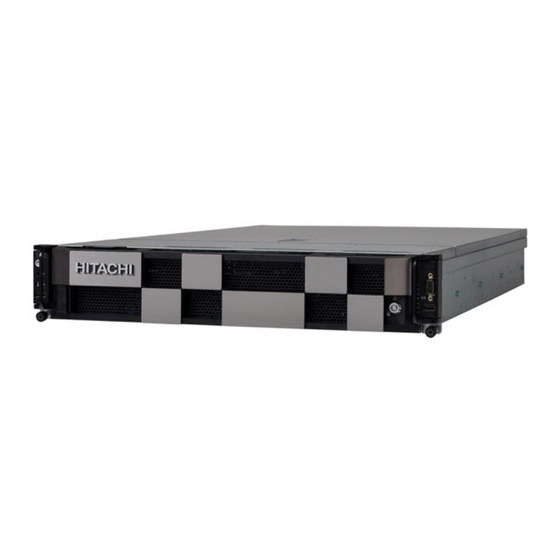
Summary of Contents for Hitachi DS220 G2
- Page 1 Hitachi Advanced Server DS220 G2 Hardware Guide MK-97HAS018-00 September 2021...
- Page 2 Hitachi, Ltd., or Hitachi Vantara LLC (collectively “Hitachi”). Licensee may make copies of the Materials provided that any such copy is: (i) created as an essential step in utilization of the Software as licensed and is used in no other manner;...
-
Page 3: Table Of Contents
ABLE OF ONTENTS ABLE OF ONTENTS Introduction ............1-1 System Features. -
Page 4: Introduction
BOUT THE YSTEM NTRODUCTION 1.1 Introduction This document provides an overview of the hardware features of the chassis, troubleshoot- ing information, and instructions on how to add and replace components of the server. For the latest version of this manual, see support.HitachiVantara.com. System Features The system comprises a 2U/30.7"... - Page 5 BOUT THE YSTEM YSTEM EATURES Specifications Table 1: System Specifications PECIFICATIONS ESCRIPTION Form factor 2U rack mount 447mm x 87.5 mm x 780 mm Chassis dimensions (W x H x D) 17.6" x 3.4" x 30.7" Processor type: Intel® Xeon® processor scalable family Processor Max.
-
Page 6: Sku Information
BOUT THE YSTEM YSTEM EATURES Table 1: System Specifications (Continued) PECIFICATIONS ESCRIPTION (2) 1200W/1600W/2200W 86mm Titanium/Platinum redundant PSU, 100- Power supply 240VAC 50/60Hz, AC/ HVDC support 1200W: 100-120/200-240Vac, 50/60Hz, 10/7A or 240Vdc, 5A (Per PSU inlet) System rating 1600W: 200-240Vac, 50/60Hz, 8A or 240Vdc, 7A (Per PSU inlet) 2200W: 200-240Vac, 50/60Hz, 10A or 240Vdc, 8A (Per PSU inlet) (6) dual rotor fans (11+1 redundant) System management... - Page 7 BOUT THE YSTEM YSTEM EATURES LFF Tiered SKU (DWGPU) LFF Tiered (SWGPU)
- Page 8 BOUT THE YSTEM YSTEM EATURES SFF Expander Tiered SKU (General) SFF Expander Tiered SKU (DWGPU)
- Page 9 BOUT THE YSTEM YSTEM EATURES SFF Expander Tiered SKU (SWGPU) SFF All Flash SKU (General)
-
Page 10: Package Contents
BOUT THE YSTEM ACKAGE ONTENTS 1.2 Package Contents (1) D53XQ-2U system (2) processor heat sinks (1) power supply unit (1) power cord (optional) Note: For exact shipping contents, contact your Hitachi sales representative. -
Page 11: A Tour Of The System
BOUT THE YSTEM OUR OF THE YSTEM 1.3 A Tour of the System System Overview The server is available as a 2.5” and 3.5” storage drive configuration. System Front View The 2.5” and 3.5” storage drive systems are displayed in the following images: Figure 1-1. - Page 12 BOUT THE YSTEM YSTEM RONT Figure 1-2. 3.5” Storage Drive System Component Overview Table 3: Front View NAME ESCRIPTION Thumb screw Secure the system to rack frame. 3.5” storage drive Housing up to twelve 3.5” storage drive tray USB port Connect to USB device.
-
Page 13: Front Control Panel (Fcp)
BOUT THE YSTEM YSTEM RONT Front Control Panel (FCP) For purposes of this procedure, the FCP is used for the numbering indicators. Figure 1-3. Front Control Panel Table 4: Front Control Panel Definition ICON NAME ESCRIPTION Power on / off Power button with Blue on –... -
Page 14: System Rear View
BOUT THE YSTEM YSTEM System Rear View Figure 1-4. System Rear View Table 5: System Rear View FEATURE ESCRIPTION Main power supply unit (PSU1). See Power Sub-System on Power sub-system page 1-12 System I/O ports See System Rear I/O on page 1-11 Expansion slot Support OCP 3.0 mezzanine card installation (CPU0) Main power supply unit (PSU0). -
Page 15: Power Sub-System
BOUT THE YSTEM YSTEM Table 6: System Rear I/O Definition (Continued) ICON NAME ESCRIPTION USB 1 port; connect to USB device USB 3.0 port USB 0 port; connect to USB device Off: Power Off/PFR Module is not installed PFR Status LED Green On: Authenticated (Only for certain Amber On: Failed... -
Page 16: System Top View
BOUT THE YSTEM YSTEM System Top View Figure 1-7. System Top View Table 9: System Top View NAME ESCRIPTION Rotate to the unlock position to unsecure the handle Latch Open toward to rear chassis to eject and lift up the top cover to remove Handle 1-13... -
Page 17: Led Status Descriptions
LED S BOUT THE YSTEM TATUS ESCRIPTIONS LED Status Descriptions Front Control Panel LEDs For location of the FCP, see System Front View on page 1-8. Figure 1-8. Front Control Panel LEDs Table 10: Front Control Panel LEDs Behavior LED D OLOR ODITION ESCRIPTIONS... -
Page 18: Bmc Management Port Leds
LED S BOUT THE YSTEM TATUS ESCRIPTIONS BMC Management Port LEDs The system mainboard includes one dedicated RJ45 GbE management port. The RJ45 con- nector has two built-in LEDs. See the following illustration and table for details. Figure 1-9. GbE RJ45 Management Table 11: RJ45 LED Descriptions ONDITION CTIVITY... - Page 19 LED S BOUT THE YSTEM TATUS ESCRIPTIONS The following LED behavior table represents LED conditions. Table 12: 2.5" Storage Drive LED Status Behavior OLOR ONDITION ESCRIPTIONS Drive is online Blue Twice per second: Identification Blinking Once per second: Rebuilding Drive Status / Fault Amber HDD failure Slot is empty...
- Page 20 Hitachi Vantara Corporate Headquarters Contact Information 2535 Augustine Drive USA: 1-800-446-0744 Santa Clara, CA 95054 USA Global: 1-858-547-4526 HitachiVantara.com | community.HitachiVantara.com HitachiVantara.com/contact...


