ABB ACS150 series User Manual
0.37...4kw;
0.5...5 hp
Hide thumbs
Also See for ACS150 series:
- User manual (156 pages) ,
- Installation instructions (4 pages) ,
- Quick installation and start-up manual (2 pages)

Related Manuals for ABB ACS150 series


Summary of Contents for ABB ACS150 series
- Page 1 บริ ษ ั ท ที . จี . คอนโทรล จ ำกั ด 1683 ทาวน์ อ ิ น ทาวน์ ซอย 9 แขวงพลั บ พลา เขตวั ง ทองหลาง กรุ ง เทพฯ 10310 โทร. 02-530-9090 แฟกซ์ . 02-530-9933 www.tgcontrol.com, www.facebook.com/tgcontrol...
-
Page 2: List Of Related Manuals
List of related manuals Drive manuals Code (English) ACS310 User’s Manual 1), 2) 3AFE68576032 Option manuals and guides 1), 2) 3AFE68642868 MUL1-R1 Installation instructions for ACS150, ACS310, ACS320, ACS350 and ACS355 MFDT-01 FlashDrop user's manual 1), 2) 3AFE68591074 Maintenance manuals 3AFE68735190 Guide for capacitor reforming in ACS50, ACS55, ACS150, ACS310, ACS350, ACS355, ACS550,... - Page 3 ACS150 drives 0.37…4 kW 0.5…5 hp User’s manual 3AFE68576032 Rev C EFFECTIVE: 2011-01-01 © 2010 ABB Oy. All Rights Reserved.
-
Page 6: Table Of Contents
Table of contents List of related manuals ............2 Table of contents Safety What this chapter contains . - Page 7 Checking the delivery ............25 Installing .
- Page 8 ABB standard macro ........
- Page 9 Hand/Auto macro ............. . 75 Default I/O connections .
- Page 10 Fault history ..............127 Alarm messages generated by the drive .
- Page 11 Providing feedback on ABB Drives manuals ........
-
Page 12: Safety
Safety What this chapter contains The chapter contains safety instructions that you must follow when installing, operating and servicing the drive. If ignored, physical injury or death may follow, or damage may occur to the drive, motor or driven equipment. Read the safety instructions before you work on the drive. -
Page 13: General Safety
• The drive is not field repairable. Never attempt to repair a malfunctioning drive; contact your local ABB representative or Authorized Service Center for replacement. • Make sure that dust from drilling does not enter the drive during the installation. -
Page 14: Safety In Start-Up And Operation
Safety in start-up and operation These warnings are intended for all who plan the operation, start up or operate the drive. WARNING! Ignoring the following instructions can cause physical injury or death, or damage to the equipment. • Before adjusting the drive and putting it into service, make sure that the motor and all driven equipment are suitable for operation throughout the speed range provided by the drive. - Page 15 Safety...
-
Page 16: Introduction To The Manual
Introduction to the manual What this chapter contains The chapter describes applicability, the target audience and purpose of this manual. It describes the contents of this manual and refers to a list of related manuals for more information. It also contains a flowchart of steps for checking the delivery, installing and commissioning the drive. -
Page 17: Related Documents
(page 169) (inside of the back cover, page 169) tells how to make product and service inquiries, get information on product training, provide feedback on ABB Drives manuals and find documents on the Internet. Related documents List of related manuals on page (inside of the front cover). -
Page 18: Quick Installation And Commissioning Flowchart
Quick installation and commissioning flowchart Task Identify the frame size of your drive: R0…R2. Operation principle and hardware description: Type designation key on page Technical data: Ratings on page Planning the electrical installation on page Plan the installation: select the cables, etc. Check the ambient conditions, ratings and required Technical data on page... - Page 19 Introduction to the manual...
-
Page 20: Operation Principle And Hardware Description
Operation principle and hardware description What this chapter contains The chapter briefly describes the operation principle, layout, type designation label and type designation information. It also shows a general diagram of power connections and control interfaces. Operation principle The ACS150 is a wall or cabinet mountable drive for controlling AC induction motors. The figure below shows the simplified main circuit diagram of the drive. -
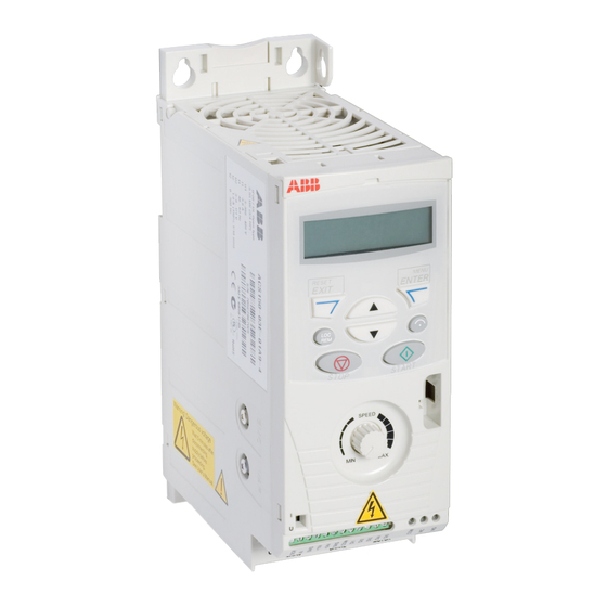
Page 21: Product Overview
Product overview Layout The layout of the drive is presented below. The construction of frame sizes R0…R2 varies to some extent. Without plates (R0 and R1) With plates (R0 and R1) 1 Cooling outlet through top cover 5 FlashDrop connection 2 Mounting holes 6 EMC filter grounding screw (EMC) 3 Integrated control panel... -
Page 22: Power Connections And Control Interfaces
Power connections and control interfaces The diagram gives an overview of connections. The I/O connections are parameterable. See chapter Application macros on page for the I/O connections for the different macros and chapter Electrical installation on page for installation in general. Potentiometer Screen Analog input... -
Page 23: Type Designation Label
A, B, C, … for product revision number XXXX: Integer starting every week from 0001 Type designation label 5 ABB MRP code of the drive 6 CE marking and C-Tick, C-UL US and RoHS marks (the label of your drive shows the valid markings) -
Page 24: Mechanical Installation
Mechanical installation What this chapter contains The chapter describes tells how to check the installation site, unpack, check the delivery and install the drive mechanically. Checking the installation site The ACS150 may be installed on the wall or in a cabinet. Check the enclosure requirements for the need to use the NEMA 1 option in wall installations (see chapter Technical data on page 137). -
Page 25: Required Tools
Required tools To install the drive, you need the following tools: • screwdrivers (as appropriate for the mounting hardware used) • wire stripper • tape measure • drill (if the drive is installed with screws/bolts) • mounting hardware: screws or bolts (if the drive is installed with screws/bolts). For the number of screws/bolts, see section With screws on page 25. -
Page 26: Checking The Delivery
Checking the delivery Check that there are no signs of damage. Notify the shipper immediately if damaged components are found. Before attempting installation and operation, check the information on the type designation label of the drive to verify that the drive is of the correct type. See section Type designation label on page 22. -
Page 27: On Din Rail
3. Position the drive onto the screws on the wall. 4. Tighten the screws in the wall securely. On DIN rail 1. Click the drive to the rail. To detach the drive, press the release lever on top of the drive as shown in Figure 1b. -
Page 28: Horizontally
Horizontally You can install the drive horizontally with screws (only back mounting, four holes). For the installation instructions, see section With screws on page 25. Note: For the required free space, see the following figure. WARNING! Horizontal mounting is permitted only for frame sizes R1 and R2 because they include a cooling fan. -
Page 29: Fasten Clamping Plates
Fasten clamping plates Note: Make sure that you do not throw the clamping plates away as they are required for proper grounding of the power and control cables. 1. Fasten the clamping plate to the plate at the bottom of the drive with the provided screws. -
Page 30: Planning The Electrical Installation
Note: The installation must always be designed and made according to applicable local laws and regulations. ABB does not assume any liability whatsoever for any installation which breaches the local laws and/or other regulations. Furthermore, if the recommendations given by ABB are not followed, the drive may experience problems that the warranty does not cover. -
Page 31: Checking The Compatibility Of The Motor And Drive
Checking the compatibility of the motor and drive Check that the 3-phase AC induction motor and the drive are compatible according to the rating table in section Ratings on page 137. The table lists the typical motor power for each drive type. Selecting the power cables General rules Dimension the input power and motor cables according to local regulations. -
Page 32: Alternative Power Cable Types
Alternative power cable types Power cable types that can be used with the drive are presented below. Allowed as motor cables Note: A separate PE conductor is required if the (recommended for input cables also) conductivity of the cable shield is not sufficient for the purpose. -
Page 33: Additional Us Requirements
Additional US requirements Type MC continuous corrugated aluminium armor cable with symmetrical grounds or shielded power cable is recommended for the motor cables if metallic conduit is not used. The power cables must be rated for 75 °C (167 °F). Conduit Where conduits must be coupled together, bridge the joint with a ground conductor bonded to the conduit on each side of the joint. -
Page 34: Selecting The Control Cables
Never mix 24 V DC and 115/230 V AC signals in the same cable. Relay cable The cable type with braided metallic screen (for example, ÖLFLEX by LAPPKABEL) has been tested and approved by ABB. Planning the electrical installation... -
Page 35: Routing The Cables
Routing the cables Route the motor cable away from other cable routes. Motor cables of several drives can be run in parallel installed next to each other. It is recommended that the motor cable, input power cable and control cables are installed on separate trays. Avoid long parallel runs of motor cables with other cables to decrease electromagnetic interference caused by the rapid changes in the drive output voltage. -
Page 36: Thermal Overload
2) Circuit breakers which have been tested by ABB with the ACS150 can be used. Fuses must be used with other circuit breakers. Contact your local ABB representative for the approved breaker types and supply network characteristics. -
Page 37: Protecting The Drive, Motor Cable And Input Power Cable Against Thermal Overload
Protecting the drive, motor cable and input power cable against thermal overload The drive protects itself and the input and motor cables against thermal overload when the cables are dimensioned according to the nominal current of the drive. No additional thermal protection devices are needed. WARNING! If the drive is connected to multiple motors, a separate thermal overload switch or a circuit breaker must be used for protecting each cable and motor. -
Page 38: Protecting The Contacts Of Relay Outputs
Protecting the contacts of relay outputs Inductive loads (relays, contactors, motors) cause voltage transients when switched off. Equip inductive loads with noise attenuating circuits (varistors, RC filters [AC] or diodes [DC]) in order to minimize the EMC emission at switch-off. If not suppressed, the disturbances may connect capacitively or inductively to other conductors in the control cable and form a risk of malfunction in other parts of the system. - Page 39 Planning the electrical installation...
-
Page 40: Electrical Installation
2. Measure the insulation resistance between each phase conductor and the Protective Earth conductor using a measuring voltage of 500 V DC. The insulation resistance of an ABB motor must exceed 100 Mohm (reference value at 25 °C or 77 °F). For the insulation resistance of other motors, please consult the manufacturer’s instructions. -
Page 41: Checking The Compatibility With It (Ungrounded) And Corner-Grounded Tn Systems
Checking the compatibility with IT (ungrounded) and corner-grounded TN systems WARNING! Disconnect the internal EMC filter when installing the drive on an IT system (an ungrounded power system or a high-resistance-grounded [over 30 ohms] power system), otherwise the system will be connected to ground potential through the EMC filter capacitors. -
Page 42: Connecting The Power Cables
Connecting the power cables Connection diagram Drive INPUT OUTPUT V1 W1 V2 W2 BRK- BRK+ For alternatives, see section Selecting the Optional brake supply disconnecting resistor device (disconnecting means) on page 29. Motor Ground the other end of the PE conductor at the distribution board. Use a separate grounding cable if the conductivity of the cable shield is insufficient (smaller than the conductivity of the phase conductor) and there is no symmetrically constructed grounding conductor in the cable (see section Selecting the... -
Page 43: Connection Procedure
Connection procedure 1. Fasten the input power cable under the grounding clamp. Crimp a cable lug onto the grounding conductor (PE) of the cable and fasten the lug under a grounding clamp screw. 2. Connect the phase conductors to the U1, V1 and W1 terminals. Use a tightening torque of 0.8 N·m (7 lbf·in). - Page 44 4. Connect the phase conductors to the U2, V2 and W2 terminals. Use a tightening torque of 0.8 N·m (7 lbf·in). 5. Connect the optional brake resistor to the BRK+ and BRK- terminals with a shielded cable using the same procedure as for the motor cable in the previous step.
-
Page 45: Connecting The Control Cables
Connecting the control cables I/O terminals The figure below shows the I/O terminals. X1A: SCR X1B: (RO)COM AI(1) (RO)NC (RO)NO +10 V +24 V DI5 digital or frequency input The default connection of the control signals depends on the application macro in use, which is selected with parameter 9902 APPLIC MACRO. -
Page 46: Pnp And Npn Configuration For Digital Inputs
PNP and NPN configuration for digital inputs You can wire the digital input terminals in either a PNP or NPN configuration. PNP connection (source) NPN connection (sink) +24V +24V External power supply for digital inputs For using an external +24 V supply for the digital inputs, see the figure below. PNP connection (source) NPN connection (sink) +24V... -
Page 47: Default I/O Connection Diagram
9902 APPLIC MACRO. The default macro is the ABB standard macro. It provides a general purpose I/O configuration with three constant speeds. Parameter values are the default values given in section Default parameter values with different macros on page 79. -
Page 48: Connection Procedure
Connection procedure 1. Analog signal (if connected): Strip the outer insulation of the analog signal cable 360 degrees and ground the bare shield under the clamp. 2. Connect the conductors to the appropriate terminals. 3. Twist the grounding conductors of the used pairs in the analog signal cable together and connect the bundle to the SCR terminal. - Page 49 4. Digital signals: Strip the outer insulation of the digital signal cable 360 degrees and ground the bare shield under the clamp. 5. Connect the conductors of the cable to the appropriate terminals. 6. Twist the grounding conductors of the used pairs in the digital signal cable together and connect the bundle to the SCR terminal.
-
Page 50: Installation Checklist
Installation checklist Checking the installation Check the mechanical and electrical installation of the drive before start-up. Go through the checklist below together with another person. Read chapter Safety page of this manual before you work on the drive. Check MECHANICAL INSTALLATION The ambient operating conditions are within allowed limits. - Page 51 Installation checklist...
-
Page 52: Start-Up And Control With I/O
APPLIC MACRO) according to how the control cables are connected. The default value 1 (ABB STANDARD) is suitable in most cases. The general parameter setting procedure in the Short parameter mode is described below. You can find more detailed instructions on setting parameters on page 65. - Page 53 9907 7. Save the parameter value by pressing Enter the motor data from the motor nameplate: Note: Set the motor data to exactly the same value ABB Motors as on the motor nameplate. Wrong motor motor M2AA 200 MLA 4...
- Page 54 • motor nominal frequency (parameter 9907 9907 MOTOR NOM FREQ) 1105 Set the maximum value for external reference REF1 (parameter 1105 REF1 MAX). 1202 Set constant speeds (drive output frequencies) 1, 2 and 3 (parameters 1202 CONST SPEED 1, 1203 CONST SPEED 2 1204 CONST SPEED 3).
- Page 55 To change the direction of the motor rotation: forward • Disconnect input power from the drive, and wait 5 minutes direction for the intermediate circuit capacitors to discharge. Measure the voltage between each input terminal (U1, V1 and W1) and earth with a multimeter to ensure that the drive is reverse discharged.
-
Page 56: How To Control The Drive Through The I/O Interface
Ensure that the control connections are wired according to the Default I/O connection diagram on page 46. connection diagram given for the ABB standard macro. Ensure that the drive is in remote control. Press key to switch In remote control, the panel display shows text REM. - Page 57 Start-up and control with I/O...
-
Page 58: Control Panel
Control panel What this chapter contains The chapter describes the control panel keys and display fields. It also instructs in using the panel in control, monitoring and changing the settings. Integrated control panel The ACS150 works with an integrated control panel, which provides basic tools for manual entry of parameter values. -
Page 59: Overview
Overview The following table summarizes the key functions and displays on the integrated control panel. No. Use LCD display – Divided into five areas: a. Upper left – Control location: LOC: drive control is local, that is, from the control panel REM: drive control is remote, such as the drive I/O. -
Page 60: Operation
Operation You can operate the control panel with the help of menus and keys. You can select an option, for example, an operation mode or a parameter, by scrolling the arrow keys until the option is visible on the display and then pressing the key. -
Page 61: How To Perform Common Tasks
How to perform common tasks The table below lists common tasks, the mode in which you can perform them and the page number where the steps of the task are described in detail. Task Mode Page How to switch between local and remote control How to start and stop the drive How to change the direction of the motor rotation How to set the frequency reference... -
Page 62: How To Start, Stop And Switch Between Local And Remote Control
How to start, stop and switch between local and remote control You can start, stop and switch between local and remote control in any mode. To be able to start or stop the drive, the drive must be in local control. Step Action Display... -
Page 63: How To Set The Frequency Reference
How to set the frequency reference You can set the local frequency reference with the integrated potentiometer in any mode when the drive is in local control if parameter 1109 LOC REF SOURCE has the default value 0 (POT). If parameter 1109 LOC REF SOURCE has been changed to 1 (KEYPAD), so that you can use keys... -
Page 64: Output Mode
Output mode In the Output mode, you can: • monitor actual values of up to three group 01 OPERATING DATA signals, one signal at a time • start, stop, change direction, switch between local and remote control and set the frequency reference. -
Page 65: Reference Mode
Reference mode In the Reference mode, you can: • view and set the frequency reference • start, stop, change direction and switch between local and remote control. How to view and set the frequency reference You can set the local frequency reference with the integrated potentiometer in any mode when the drive is in local control if parameter 1109 LOC REF SOURCE has... -
Page 66: Parameter Modes
Parameter modes There are two parameter modes: Short parameter mode and Long parameter mode. Both function identically, except that the Short parameter mode shows only the minimum number of parameters typically required to set up the drive (see section Parameters in the Short parameter mode on page 80). -
Page 67: How To Select The Monitored Signals
Step Action Display Use keys to select the parameter value. When you have changed the parameter value, starts flashing. 1203 • To save the displayed parameter value, press • To cancel the new value and keep the original, press How to select the monitored signals Step Action Display... -
Page 68: Changed Parameters Mode
Changed parameters mode In the Changed parameters mode, you can: • view a list of all parameters that have been changed from the macro default values • change these parameters • start, stop, change direction, switch between local and remote control and set the frequency reference. - Page 69 Control panel...
-
Page 70: Application Macros
Macro Suitable applications ABB standard Ordinary speed control applications where no, one, two or three constant speeds are used. Start/stop is controlled with one digital input (level start and stop). It is possible to switch between two acceleration and deceleration times. -
Page 71: Summary Of I/O Connections Of Application Macros
Summary of I/O connections of application macros The following table gives the summary of the default I/O connections of all application macros. Macro Input/output Motor ABB standard 3-wire Alternate Hand/Auto PID control potentiometer Frequency Frequency Frequency Frequency ref. Freq. ref. -
Page 72: Abb Standard Macro
ABB standard macro This is the default macro. It provides a general purpose I/O configuration with three constant speeds. Parameter values are the default values given in chapter Actual signals and parameters, starting from page 79. If you use other than the default connections presented below, see section terminals on page 44. -
Page 73: 3-Wire Macro
3-wire macro This macro is used when the drive is controlled using momentary push-buttons. It provides three constant speeds. To enable the macro, set the value of parameter 9902 APPLIC MACRO to 2 (3-WIRE). For the parameter default values, see section Default parameter values with different macros on page 79. -
Page 74: Alternate Macro
Alternate macro This macro provides an I/O configuration adapted to a sequence of DI control signals used when alternating the rotation direction of the drive. To enable the macro, set the value of parameter 9902 APPLIC MACRO to 3 (ALTERNATE). For the parameter default values, see section Default parameter values with different macros... -
Page 75: Motor Potentiometer Macro
Motor potentiometer macro This macro provides a cost-effective interface for PLCs that vary the speed of the drive using only digital signals. To enable the macro, set the value of parameter 9902 APPLIC MACRO to 4 (MOTOR POT). For the parameter default values, see section Default parameter values with different macros on page 79. -
Page 76: Hand/Auto Macro
Hand/Auto macro This macro can be used when switching between two external control devices is needed. To enable the macro, set the value of parameter 9902 APPLIC MACRO to 5 (HAND/AUTO). For the parameter default values, see section Default parameter values with different macros on page 79. -
Page 77: Pid Control Macro
PID control macro This macro provides parameter settings for closed-loop control systems such as pressure control, flow control, and so on. Control can also be switched to speed control using a digital input. To enable the macro, set the value of parameter 9902 APPLIC MACRO to 6 (PID CONTROL). -
Page 78: User Macros
User macros In addition to the standard application macros, it is possible to create three user macros. The user macro allows the user to save the parameter settings, including group 99 START-UP DATA, into the permanent memory and recall the data at a later time. - Page 79 Application macros...
-
Page 80: Actual Signals And Parameters
5 = DI5 0 = NOT SEL 5 = DI5 0 = NOT SEL 0 = NOT SEL 0 = NOT SEL 9902 APPLIC 1 = ABB 2 = 3-WIRE 4 = MOTOR 5 = HAND/ 6 = PID MACRO STANDARD ALTERNATE... -
Page 81: Parameters In The Short Parameter Mode
1 = ABB chapter Application macros on page 69. STANDARD 1 = ABB STANDARD Standard macro for constant speed applications 2 = 3-WIRE 3-wire macro for constant speed applications 3 = ALTERNATE Alternate macro for start forward and start reverse applications... -
Page 82: 04 Fault History
Parameters in the Short parameter mode Name/Value Description 9905 MOTOR NOM VOLT Defines the nominal motor voltage. Must be equal to the value on the motor 200 V rating plate. The drive cannot supply the motor with a voltage greater than E units: the input power voltage. -
Page 83: 12 Constant Speeds
Parameters in the Short parameter mode Name/Value Description 12 CONSTANT SPEEDS Constant speeds. Constant speed activation overrides the external speed reference. Constant speed selections are ignored if drive is in the local control mode. As default constant speed selection is made through digital inputs DI3 and DI4.1 = DI active, 0 = DI inactive. -
Page 84: 22 Accel/Decel
Parameters in the Short parameter mode Name/Value Description 22 ACCEL/DECEL Acceleration and deceleration times 2202 ACCELER TIME 1 5.0 s Defines the acceleration time 1, that is the time required for the speed to change from zero to the speed defined by parameter 2008 MAXIMUM FREQ. -
Page 85: Actual Signals
Actual signals The following table includes the descriptions of all actual signal. Actual signals Name/Value Description 01 OPERATING DATA Basic signals for monitoring the drive (read-only). For actual signal supervision, see parameter group SUPERVISION. For selection of an actual signal to be displayed on the control panel, see parameter group 34 PANEL DISPLAY. -
Page 86: 04 Fault History
Actual signals Name/Value Description 0142 REVOLUTION CNTR Motor revolution counter (millions of revolutions). The counter can be reset by pressing the UP and DOWN keys simultaneously when the control panel is in the Parameter mode. 0143 DRIVE ON TIME HI Drive control board power-on time in days. -
Page 87: Parameters In The Long Parameter Mode
Parameters in the Long parameter mode The following table includes the complete descriptions of all parameters that are visible only in the Long parameter mode. See section Parameter modes on page for how to select the parameter mode. Parameters in the Long parameter mode Index Name/Selection Description 10 START/STOP/DIR... - Page 88 Parameters in the Long parameter mode Index Name/Selection Description 1002 EXT2 COMMANDS 0 = NOT SEL Defines the connections and the source for the start, stop and direction commands for external control location 2 (EXT2). See parameter 1001 EXT1 COMMANDS. 1003 DIRECTION Enables the control of rotation direction of the motor, or fixes the direction.
- Page 89 Parameters in the Long parameter mode Index Name/Selection Description 1010 JOGGING SEL 0 = NOT SEL Defines the signal that activates the jogging function. The jogging function is typically used to control a cyclical movement of a machine section. One push button controls the drive through the whole cycle: When it is on, the drive starts, accelerates to a preset speed at a preset rate.
-
Page 90: Reference Select
Parameters in the Long parameter mode Index Name/Selection Description 0 = NOT SEL Not selected -1 = DI1(INV) Inverted digital input DI1. 1 = jogging inactive, 0 = jogging active. -2 = DI2(INV) See selection DI1(INV). -3 = DI3(INV) See selection DI1(INV). -4 = DI4(INV) See selection DI1(INV). - Page 91 Parameters in the Long parameter mode Index Name/Selection Description 3 = AI1/JOYST Analog input AI1 as joystick. The minimum input signal runs the motor at the maximum reference in the reverse direction, the maximum input at the maximum reference in the forward direction. Minimum and maximum references are defined by parameters 1104 REF1 MIN and...
- Page 92 Parameters in the Long parameter mode Index Name/Selection Description 1104 REF1 MIN 0.0 Hz Defines the minimum value for external reference REF1. Corresponds to the minimum setting of the used source signal. 0.0…500.0 Hz Minimum value. Example: Analog input AI1 is selected as the reference source (value of parameter 1103 REF1 SELECT is AI1).
-
Page 93: 12 Constant Speeds
Parameters in the Long parameter mode Index Name/Selection Description 12 CONSTANT SPEEDS Constant speed selection and values. It is possible to define seven positive constant speeds. Constant speeds are selected with digital inputs. Constant speed activation overrides the external speed reference. Constant speed selections are ignored if drive is in the local control mode. - Page 94 Parameters in the Long parameter mode Index Name/Selection Description -5 = DI5(INV) Speed defined by parameter 1202 CONST SPEED 1 is activated through inverted digital input DI5. 0 = active, 1 = inactive. -7 = DI1,2 (INV) Constant speed selection through inverted digital inputs DI1 and DI2. 1 = DI active, 0 = DI inactive.
-
Page 95: 13 Analog Inputs
Parameters in the Long parameter mode Index Name/Selection Description 13 ANALOG INPUTS Analog input signal processing 1301 MINIMUM AI1 Defines the minimum %-value that corresponds to minimum mA/(V) signal for 0.0% analog input AI1. When used as a reference, the value corresponds to the reference minimum setting. - Page 96 Parameters in the Long parameter mode Index Name/Selection Description 7 = STARTED The drive has received a start command. Relay is energized even if Run enable signal is off. Relay is de-energized when drive receives a stop command or a fault occurs. 8 = SUPRV 1 OVER Status according to supervision parameters 3201...
-
Page 97: System Controls
Parameters in the Long parameter mode Index Name/Selection Description 16 SYSTEM Run enable, parameter lock etc. CONTROLS 1601 RUN ENABLE Selects a source for the external Run enable signal. 0 = NOT SEL 0 = NOT SEL Allows the drive to start without an external Run enable signal. 1 = DI1 External signal required through digital input DI1. - Page 98 Parameters in the Long parameter mode Index Name/Selection Description -3 = DI3(INV) See selection DI1(INV). -4 = DI4(INV) See selection DI1(INV). -5 = DI5(INV) See selection DI1(INV). 1606 LOCAL LOCK 0 = NOT SEL Disables entering the local control mode or selects the source for the local control mode lock signal.
-
Page 99: 18 Freq Input
Parameters in the Long parameter mode Index Name/Selection Description 18 FREQ INPUT Frequency input signal processing. Digital input DI5 can be programmed as a frequency input. Frequency input can be used as external reference signal source. See parameter 1103/1106 REF1/2 SELECT. 1801 FREQ INPUT MIN Defines the minimum input value when DI5 is used as a frequency input. -
Page 100: 21 Start/Stop
OVERVOLT CTRL to selection 0 (DISABLE). 1 = EXTERNAL External brake chopper control. Note: The drive is compatible only with ABB ACS-BRK-X brake units. Note: Ensure the brake unit is installed and the overvoltage control is switched off by setting parameter 2005 OVERVOLT CTRL to selection 0 (DISABLE). - Page 101 Parameters in the Long parameter mode Index Name/Selection Description 2103 DC MAGN TIME Defines the pre-magnetizing time. See parameter 2101 START FUNCTION. 0.30 s After the start command, the drive automatically pre-magnetizes the motor for the defined time. 0.00…10.00 s Magnetizing time.
-
Page 102: 22 Accel/Decel
Parameters in the Long parameter mode Index Name/Selection Description -4 = DI4(INV) See selection DI1(INV). -5 = DI5(INV) See selection DI1(INV). 2110 TORQ BOOST CURR Defines the maximum supplied current during torque boost. See parameter 100% 2101 START FUNCTION. 15…300% Value in percent 2112 ZERO SPEED DELAY Defines the delay for the Zero speed delay function. - Page 103 Parameters in the Long parameter mode Index Name/Selection Description -3 = DI3(INV) See selection DI1(INV). -4 = DI4(INV) See selection DI1(INV). -5 = DI5(INV) See selection DI1(INV). 2202 ACCELER TIME 1 5.0 s Defines the acceleration time 1, that is the time required for the speed to change from zero to the speed defined by parameter 2008 MAXIMUM FREQ.
- Page 104 Parameters in the Long parameter mode Index Name/Selection Description 2205 ACCELER TIME 2 60.0 s Defines the acceleration time 2, that is the time required for the speed to change from zero to the speed defined by parameter 2008 MAXIMUM FREQ. See parameter 2202 ACCELER TIME 1.
-
Page 105: 25 Critical Speeds
Parameters in the Long parameter mode Index Name/Selection Description 25 CRITICAL SPEEDS Speed bands within which the drive is not allowed to operate. A Critical Speeds function is available for applications where it is necessary to avoid certain motor speeds or speed bands because of for example, mechanical resonance problems. -
Page 106: 26 Motor Control
Parameters in the Long parameter mode Index Name/Selection Description 26 MOTOR CONTROL Motor control variables 2601 FLUX OPT ENABLE Activates/deactivates the Flux optimisation function. Flux optimisation 0 = OFF reduces the total energy consumption and motor noise level when the drive operates below the nominal load. - Page 107 Parameters in the Long parameter mode Index Name/Selection Description 2607 SWITCH FREQ CTRL Activates the switching frequency control. When active, the selection of 1 = ON parameter 2606 SWITCHING FREQ is limited when the drive internal temperature increases. See the figure below. This function allows the highest possible switching frequency at a specific operation point.
-
Page 108: 30 Fault Functions
Parameters in the Long parameter mode Index Name/Selection Description 30 FAULT FUNCTIONS Programmable protection functions 3001 AI- Page 109 Parameters in the Long parameter mode Index Name/Selection Description 3005 MOT THERM PROT 1 = FAULT Selects how the drive reacts when motor overtemperature is detected. The drive calculates the temperature of the motor on the basis of the following assumptions: 1) The motor is in the ambient temperature of 30 °C when power is applied to the drive.
- Page 110 Parameters in the Long parameter mode Index Name/Selection Description 3007 MOT LOAD CURVE Defines the load curve together with parameters 3008 ZERO SPEED LOAD 100% 3009 BREAK POINT FREQ. With the default value 100%, motor overload protection is functioning when the constant current exceeds 127% of the parameter 9906 MOTOR NOM CURR value.
- Page 111 Parameters in the Long parameter mode Index Name/Selection Description 3010 STALL FUNCTION 0 = NOT SEL Selects how the drive reacts to a motor stall condition. The protection wakes up if the drive has operated in a stall region (see the figure below) longer than the time set by parameter 3012 STALL TIME.
- Page 112 Parameters in the Long parameter mode Index Name/Selection Description 3015 UNDERLOAD CURVE Selects the load curve for the underload function. See parameter 3013 UNDERLOAD FUNC. = nominal torque of the motor ƒ = nominal frequency of the motor (par. 9907) Underload curve types 2.4 ·...
Page 113: 31 Automatic Reset
Parameters in the Long parameter mode Index Name/Selection Description 3023 WIRING FAULT 1 = ENABLE Selects how the drive reacts when incorrect input power and motor cable connection is detected (that is the input power cable is connected to the motor connection of the drive).- Page 114 Parameters in the Long parameter mode Index Name/Selection Description 3107 AR AI
Page 115: 32 Supervision
Parameters in the Long parameter mode Index Name/Selection Description 32 SUPERVISION Signal supervision. The drive monitors whether certain user selectable variables are within the user-defined limits. The user may set limits for speed, current etc. Supervision status can be monitored with relay output. See parameter group 14 RELAY OUTPUTS.Page 116: 33 Information
Parameters in the Long parameter mode Index Name/Selection Description 0, x…x Parameter index in group 01 OPERATING DATA. For example, 102 = 0102 SPEED. 0 = not selected. 3202 SUPERV 1 LIM LO Defines the low limit for the first supervised signal selected by parameter 3201 SUPERV 1 PARAM.Page 117: 34 Panel Display
Parameters in the Long parameter mode Index Name/Selection Description 3304 DRIVE RATING Displays the drive current and voltage ratings. 0x0000 hex 0000…FFFF hex Value in format XXXY hex: XXX = Nominal current of the drive in amperes. An “A” indicates decimal point.- Page 118 Parameters in the Long parameter mode Index Name/Selection Description Defines the format for the displayed signal selected by parameter 3401 9 = DIRECT 3404 OUTPUT1 DSP FORM SIGNAL1 PARAM. 0 = +/-0 Signed/Unsigned value. Unit is selected by parameter 3405 OUTPUT 1 UNIT.
- Page 119 Parameters in the Long parameter mode Index Name/Selection Description 3408 SIGNAL2 PARAM Selects the second signal to be displayed on the control panel in the Output mode. See parameter 3401 SIGNAL1 PARAM. 0, 102…162 Parameter index in group 01 OPERATING DATA.
Page 120: Process Pid Set 1
Parameters in the Long parameter mode Index Name/Selection Description 3421 OUTPUT3 MAX Sets the maximum display value for the signal selected by parameter 3415 SIGNAL3 PARAM. See parameter 3402 SIGNAL1 MIN. x…x Setting range depends on parameter 3415 SIGNAL3 PARAM setting. 40 PROCESS PID SET 1 Process PID (PID1) control parameter set 1.- Page 121 Parameters in the Long parameter mode Index Name/Selection Description 4004 PID DERIV FILTER 1.0 s Defines the filter time constant for the derivative part of the process PID controller. Increasing the filter time smooths the derivative and reduces noise. 0.0…10.0 s Filter time constant.
- Page 122 Parameters in the Long parameter mode Index Name/Selection Description 11 = DI3U,4D(RNC) Digital input DI3: Reference increase. Digital input DI4: Reference decrease. Stop command resets the reference to zero. When this selection becomes active (in change from EXT1 to EXT2), the reference initializes to the value used when this control location (and this selection) was active the last time.
- Page 123 Parameters in the Long parameter mode Index Name/Selection Description 3 = ACT1+ACT2 Addition of ACT1 and ACT2 4 = ACT1*ACT2 Multiplication of ACT1 and ACT2 5 = ACT1/ACT2 Division of ACT1 and ACT2 6 = MIN(ACT1,2) Selects the smaller of ACT1 and ACT2 7 = MAX(ACT1,2) Selects the higher of ACT1 and ACT2 8 = sqrt(ACT1-2)
- Page 124 Parameters in the Long parameter mode Index Name/Selection Description 4019 ACT1 MAXIMUM 100% Defines the maximum value for the variable ACT1 if an analog input is selected as a source for ACT1. See parameter 4016 ACT1 INPUT. The minimum (4018 ACT1 MINIMUM) and maximum settings of ACT1 define how the voltage/current signal received from the measuring device is converted to a percentage value used by the process PID controller.
Page 125: 99 Start-Up Data
Application macro. Definition of motor set-up data. 9902 APPLIC MACRO Selects the application macro or activates FlashDrop parameter values. See 1 = ABB chapter Application macros on page 69. STANDARD 1 = ABB STANDARD Standard macro for constant speed applications Actual signals and parameters...- Page 126 Parameters in the Long parameter mode Index Name/Selection Description 2 = 3-WIRE 3-wire macro for constant speed applications 3 = ALTERNATE Alternate macro for start forward and start reverse applications 4 = MOTOR POT Motor potentiometer macro for digital signal speed control applications 5 = HAND/AUTO Hand/Auto macro to be used when two control devices are connected to the drive:...
- Page 127 Parameters in the Long parameter mode Index Name/Selection Description 9905 MOTOR NOM VOLT 200 V Defines the nominal motor voltage. Must be equal to the value on the motor rating plate. The drive cannot supply the motor with a voltage greater than E units: the input power voltage.
Page 128: Fault Tracing
An alarm or fault message on the panel display indicates abnormal drive status. Using the information given in this chapter most alarm and fault causes can be identified and corrected. If not, contact an ABB representative. How to reset The drive can be reset either by pressing the keypad key on the control panel, through digital input, or by switching the supply voltage off for a while.Page 129: Alarm Messages Generated By The Drive
Alarm messages generated by the drive CODE ALARM CAUSE WHAT TO DO A2001 OVERCURRENT Output current limit controller is Check motor load. active. (programmable fault Check acceleration time (parameters 2202 function, parameter ACCELER TIME 1 and 2205 ACCELER 1610 DISPLAY TIME 2).- Page 130 Stop drive and change parameter value. A5024 Drive is executing task. Wait until task is completed. A5026 Value is at or below minimum limit. Contact your local ABB representative. A5027 Value is at or above maximum limit. Contact your local ABB representative. A5028 Invalid value Contact your local ABB representative.
Page 131: Fault Messages Generated By The Drive
Fault messages generated by the drive CODE FAULT CAUSE WHAT TO DO F0001 OVERCURRENT Check motor load. Output current has exceeded trip level. Check acceleration time (parameters 2202 ACCELER TIME 1 and 2205 ACCELER TIME 2). Overcurrent trip limit for drive is 325% of drive nominal current.- Page 132 Check motor power against drive power. parameters 3013...3015) F0018 THERM FAIL Drive internal fault. Thermistor Contact your local ABB representative. used for drive internal temperature measurement is open or short-circuited. F0021 CURR MEAS Drive internal fault. Current Contact your local ABB representative.
- Page 133 CODE FAULT CAUSE WHAT TO DO F0201 DSP T1 System error Contact your local ABB representative. OVERLOAD F0202 DSP T2 OVERLOAD F0203 DSP T3 OVERLOAD F0204 DSP STACK ERROR F0206 MMIO ID ERROR Internal I/O Control board (MMIO) Contact your local ABB representative.
Page 134: Maintenance
Check that tightening torque power terminals values given in chapter Technical data are met. Consult your local ABB Service representative for more details on the maintenance. and select Drive Services – On the Internet, go to http://www.abb.com/drives Maintenance and Field Services.Page 135: Cooling Fan
Fan failure can be predicted by the increasing noise from the fan bearings. If the drive is operated in a critical part of a process, fan replacement is recommended once these symptoms start appearing. Replacement fans are available from ABB. Do not use other than ABB specified spare parts.Page 136: Capacitors
For information on reforming the capacitors, refer to Guide for capacitor reforming in ACS50, ACS55, ACS150, ACS310, ACS320, ACS350, ACS550 and ACH550 (3AFE68735190 [English]), available on the internet (go to http://www.abb.com and enter the code in the Search field. Maintenance...Page 137: Power Connections
Power connections WARNING! Read and follow the instructions in chapter Safety page 11. Ignoring the instructions can cause physical injury or death, or damage to the equipment. 1. Stop the drive and disconnect it from the power line. Wait for five minutes to let the drive DC capacitors discharge.Page 138: Technical Data
Technical data What this chapter contains The chapter contains the technical specifications of the drive, for example, the ratings, sizes and technical requirements as well as provisions for fulfilling the requirements for CE and other marks. Ratings Current and power The current and power ratings are given below.Page 139: Symbols
Symbols Input continuous rms input current (for dimensioning cables and fuses) (480 V) continuous rms input current (for dimensioning cables and fuses) for drives with 480 V input voltage Output continuous rms current. 50% overload is allowed for one minute every ten minutes. maximum (50% overload) current allowed for one minute every ten minutes 2,1min/10min maximum output current.Page 140: Switching Frequency Derating, I2N
Switching frequency derating, I The drive derates itself automatically when parameter 2607 SWITCH FREQ CTRL = 1 (ON). Drive voltage rating Switching frequency = 380…480 V = 200…240 V 4 kHz No derating No derating 8 kHz derated to 90%. derated to 75% for R0 or to 80% for R1 and R2.Page 141: Power Cable Sizes And Fuses
Power cable sizes and fuses Cable dimensioning for rated currents (I ) is shown in the table below together with the corresponding fuse types for short-circuit protection of the input power cable. The rated fuse currents given in the table are the maximums for the mentioned fuse types.Page 142: Dimensions, Weights And Free Space Requirements
Dimensions, weights and free space requirements Dimensions and weights Dimensions and weights Frame size IP20 (cabinet) / UL open Weight 6.65 7.95 9.41 2.76 5.59 6.65 7.95 9.41 2.76 5.59 1.3/1.2 2.9/2.6 6.65 7.95 9.41 4.13 5.59 = 380…480 V: 1.2 kg / 2.6 lb = 200…240 V: 1.3 kg / 2.9 lb, U 00353783.xls J Dimensions and weights...Page 143: Losses, Cooling Data And Noise
Losses, cooling data and noise Losses and cooling data Frame size R0 has natural convection cooling. Frame sizes R1…R2 are provided with an internal fan. The air flow direction is from bottom to top. The table below specifies the heat dissipation in the main circuit at nominal load and in the control circuit with minimum load (I/O not in use) and maximum load (all digital inputs in the on state and the fan in use).Page 144: Terminal And Lead-Through Data For The Power Cables
Terminal and lead-through data for the power cables U1, V1, W1, U2, V2, W2, BRK+ and BRK- Frame Max cable size diameter for NEMA 1 U1, V1, W1, Max. terminal size Tightening Max. clamp size Tightening U2, V2, W2 flexible/rigid torque solid or stranded torque...Page 145: Electric Power Network Specification
Electric power network specification Voltage (U 200/208/220/230/240 V AC 1-phase for 200 V AC drives 200/208/220/230/240 V AC 3-phase for 200 V AC drives 380/400/415/440/460/480 V AC 3-phase for 400 V AC drives Regular 10% variation from converter nominal voltage is allowed as default. Short-circuit capacity Maximum allowed prospective short-circuit current at the input power connection as defined in IEC 60439-1 and UL 508C is 100 kA.- Page 146 Maximum motor cable length is determined by the drive’s operational factors. Contact your local ABB representative for the exact maximum lengths when using external EMC filters Note 1: In multimotor systems, the calculated sum of all motor cable lengths must not exceed the maximum motor cable length given in the table.
Page 147: Control Connection Data
The brake resistor output is conditionally short-circuit proof by IEC/EN 61800-5-1 and UL (IEC 61800-5-1, IEC 60439-1, 508C. For correct fuse selection, contact your local ABB representative. Rated conditional UL 508C) short-circuit current as defined in IEC 60439-1 and the short-circuit test current by UL 508C is 100 kA.Page 148: Ambient Conditions
Ambient conditions Environmental limits for the drive are given below. The drive is to be used in a heated indoor controlled environment. Operation Storage Transportation installed for stationary use in the protective package in the protective package Installation site altitude 0 to 2000 m (6600 ft) above sea level (above 1000 m [3300 ft], see...Page 149: Applicable Standards
EU. They must be removed and handled according to local regulations. For further information on environmental aspects and more detailed recycling instructions, please contact your local ABB distributor. Applicable standards The drive complies with the following standards: •...Page 150: Compliance
Category C1 The emission limits are complied with the following provisions: 1. The optional EMC filter is selected according to the ABB documentation and installed as specified in the EMC filter manual. 2. The motor and control cables are selected as specified in this manual.Page 151: Ul Marking
Note: It is not allowed to install a drive with the internal EMC filter connected on a corner-grounded TN system as this would damage the drive. UL marking See the type designation label for the valid markings of your drive. The UL mark is attached to the drive to verify that it meets UL requirements.Page 152: Brake Resistors
= length of the braking cycle (s). Resistor types shown in the following table are pre-dimensioned resistors using the maximum braking power with cyclic braking shown in the table. Resistors are available from ABB. Information is subject to change without further notice. Technical data...- Page 153 120 seconds, at 40 °C ambient temperature. Note: The brake resistors listed in the table are available in Europe. They do not apply to the USA. Contact your local ABB representative for more information. Symbols = minimum allowed brake resistor that can be connected to the brake chopper = maximum allowed brake resistor that allows R = maximum braking capacity of the drive, must exceed the desired braking power.
Page 154: Selecting The Brake Resistor Cables
Selecting the brake resistor cables Use a shielded cable with the same conductor size as for drive input cabling (see section Terminal and lead-through data for the power cables on page 143). The maximum length of the resistor cable(s) is 5 m (16 ft). Placing the brake resistor Install all resistors in a place where they will cool.Page 155: Start-Up
Start-up To enable resistor braking, switch off the drive’s overvoltage control by setting parameter 2005 OVERVOLT CTRL to 0 (DISABLE). Technical data...Page 156: Dimension Drawings
Dimension drawings Dimensional drawings of the ACS150 are shown below. The dimensions are given in millimeters and [inches]. Dimension drawings...Page 157: Frame Sizes R0 And R1, Ip20 (Cabinet Installation) / Ul Open
Frame sizes R0 and R1, IP20 (cabinet installation) / UL open R1 and R0 are identical except for the fan at the top of R1. EMC VAR Dimension drawings...Page 158: Frame Sizes R0 And R1, Ip20 / Nema 1
Frame sizes R0 and R1, IP20 / NEMA 1 R1 and R0 are identical except for the fan at the top of R1. EMC VAR Dimension drawings...Page 159: Frame Size R2, Ip20 (Cabinet Installation) / Ul Open
I 0 [ 39 5 [ I 9 7 5 [ I 9 7 · 10 [ 394] 1\,) "'C 1\,) [ 3 9 I • I I • I 144 [5 67] 85 [ 3 35 142 [ 5 57 J 11---111 = '= Clll<;VG...Page 160: Frame Size R2, Ip20 / Nema 1
·II ,---=== =· ==I@! ,-----., L (© Frame size · IP20 I NEMA 1 §- Page 161 4 I , 5 [ I 6 4...
- Page 163 Dimension drawings...
Page 164: Appendix: Process Pid Control
Appendix: Process PID control What this chapter contains The chapter contains instructions on quick configuration of the process control, gives an application example and describes the PID sleep functionality. Process PID control There is a built-in PID controller in the drive. The controller can be used to control process variables such as pressure, flow or fluid level.Page 165: Pressure Boost Pump
4017 ACT2 INPUT: If a second feedback is used, configure also this actual value (4020 ACT2 MINIMUM and 4021 ACT2 MAXIMUM). 4001 GAIN, 4002 INTEGRATION TIME, 4003 DERIVATION TIME, 4005 ERROR VALUE INV: Configure the desired gain, integration time, derivation time and error value inversion when needed.Page 166: How To Scale The Pid Actual (Feedback) Signal 0...10 Bar / 4...20 Ma
How to scale the PID actual (feedback) signal 0…10 bar / 4…20 mA PID feedback is connected to AI1 and 4016 ACT1 INPUT is set to AI1. 1. Set 9902 APPLICATION MACRO to 6 (PID CONTROL). Check scaling: 1301 MINIMUM AI1 as default 20% and 1302 MAXIMUM AI1 as default 100%. Check that 1106 REF2 SELECT is set to 19 (PID1OUT).Page 167: Pid Sleep Functionality
PID sleep functionality The block diagram below illustrates the sleep function enable/disable logic. The sleep function can be put into use only when the PID control is active. Compare Select output NOT SEL frequency INTERNAL 1<2 Delay 4023 Set/Reset 4022 &...- Page 168 Sleep function for a PID controlled pressure boost pump (when parameter 4022 SLEEP SELECTION is set to 7 = INTERNAL): The water consumption falls at night. As a consequence, the PID process controller decreases the motor speed. However, due to natural losses in the pipes and the low efficiency of the centrifugal pump at low speeds, the motor does not stop but keeps rotating.
- Page 169 Appendix: Process PID control...
- Page 170 EMC directive 2004/108/EC. Declaration Conformi t y according to these ectives is available from manufacturer. ABB Oy furthermore declares that is not allowed to put the equipment into service until the machinery into which it to be incorporated or of which...
Page 172: Further Information
Product and service inquiries Address any inquiries about the product to your local ABB representative, quoting the type designation and serial number of the unit in question. A listing of ABB sales, support and service contacts can be found by navigating to www.abb.com/drives...- Page 173 Contact us ABB Oy ABB Inc. ABB Beijing Drive Systems Co. Ltd. Drives Automation Technologies No. 1, Block D, A-10 Jiuxianqiao Beilu P.O. Box 184 Drives & Motors Chaoyang District Beijing, P.R. China, 100015 FI-00381 HELSINKI 16250 West Glendale Drive...