ABB ACS150 User Manual
Hide thumbs
Also See for ACS150:
- User manual (173 pages) ,
- Installation instructions (4 pages) ,
- Quick installation and start-up manual (2 pages)

Related Manuals for ABB ACS150


Summary of Contents for ABB ACS150
- Page 1 ACS150 QUOTE OR BUY ONLINE www.inverterdrive.co.uk User’s Manual ACS150 Drives (0.37…4 kW, 0.5…5 HP)
- Page 3 ACS150 Drives 0.37…4 kW 0.5…5 HP User’s Manual 3AFE68576032 Rev A EFFECTIVE: 7.12.2005 © 2005 ABB Oy. All Rights Reserved.
-
Page 5: Safety
Safety What this chapter contains The chapter contains the safety instructions which you must follow when installing, operating and servicing the drive. If ignored, physical injury or death may follow, or damage may occur to the drive, motor or driven equipment. Read the safety instructions before you work on the drive. -
Page 6: Operation And Start-Up
• The drive is not field repairable. Never attempt to repair a malfunctioning drive; contact your local ABB representative or Authorized Service Center for replacement. • Make sure that dust from drilling does not enter the drive during the installation. -
Page 7: Table Of Contents
Table of contents Safety What this chapter contains ............5 Use of warning symbols . - Page 8 ABB Standard macro ........
- Page 9 10 START/STOP/DIR ............69 11 REFERENCE SELECT .
- Page 10 Efficiency ..............115 Cooling .
-
Page 11: About The Manual
It contains a flowchart of steps for checking the delivery and installing and commissioning the drive. The flowchart refers to chapters/sections in this manual. Compatibility The manual is compatible with the ACS150 drive firmware version 1.30b or later. See parameter 3301 FW VERSION. -
Page 12: Installation And Commissioning Flowchart
Installation and commissioning flowchart Task Identify the frame size of your drive: R0…R2. Technical data: Ratings on page Plan the installation: select the cables, etc. Planning electrical installation on page Check the ambient conditions, ratings and required Technical data on page cooling air flow. -
Page 13: Hardware Description
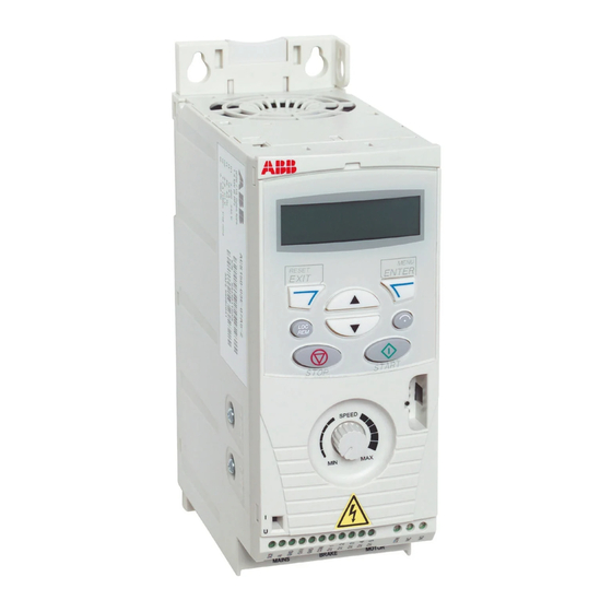
The chapter describes the construction and type code information in short. Overview The ACS150 is a wall or cabinet mountable drive for controlling AC motors. The construction of frame sizes R0…R2 varies to some extent. Without plates (R0 and R1) -
Page 14: Overview: Connections And Switch
Overview: Connections and switch The diagram shows the connections and switch of the ACS150. FlashDrop connection EMC filter grounding screw Varistor grounding screw Potentiometer AI type selection V / mA Relay output Analog input 250 VAC / 30 VDC 0(2)…+10 VDC or 0(4)…+20 mA... -
Page 15: Type Code
The type code contains information on the specifications and configuration of the drive. You find the type code on the type designation label attached to the drive. The first digits from the left express the basic configuration, for example ACS150-03E- 08A8-4. The explanations of the type code selections are described below. - Page 16 Hardware description...
-
Page 17: Mechanical Installation
Mechanical installation What this chapter contains The chapter describes the mechanical installation procedure of the drive. Unpacking the drive The drive (1) is delivered in a package that also contains the following items (frame size R0 shown in the figure): •... -
Page 18: Before Installation
Before installation The ACS150 may be installed on the wall or in a cabinet. Check the enclosure requirements for the need to use the NEMA 1 option in wall installations (see chapter Technical data). -
Page 19: Mounting The Drive
Free space around the drive The required free space for cooling above and below the drive is 75 mm (3 in.). No free space is required on the sides of the drive, so they can be mounted side by side. Mounting the drive Mount the drive Note: Make sure that dust from drilling does not enter the drive during the... - Page 20 Fasten clamping plates 1. Fasten the clamping plate to the plate at the bottom of the drive with the provided screws. 2. Fasten the I/O clamping plate to the clamping plate with the provided screws. Mechanical installation...
-
Page 21: Planning Electrical Installation
Note: The installation must always be designed and made according to applicable local laws and regulations. ABB does not assume any liability whatsoever for any installation which breaches the local laws and/or other regulations. -
Page 22: Thermal Overload And Short-Circuit Protection
Circuit breakers (To be defined) Circuit breakers which have been tested by ABB with the ACS150 can be used. Fuses must be used with other circuit breakers. Contact your local ABB representative for approved breaker types and supply network characteristics. -
Page 23: Selecting The Power Cables
Selecting the power cables General rules Dimension the input power and motor cables according to local regulations. • The cable must be able to carry the drive load current. See chapter Technical data for the rated currents. ° • The cable must be rated for at least 70 C maximum permissible temperature of the conductor in continuous use. - Page 24 Motor cable shield To function as a protective conductor, the shield must have the same cross-sectional area as the phase conductors when they are made of the same metal. To effectively suppress radiated and conducted radio-frequency emissions, the shield conductivity must be at least 1/10 of the phase conductor conductivity. The requirements are easily met with a copper or aluminium shield.
-
Page 25: Protecting The Relay Output Contact And Attenuating Disturbances In Case Of Inductive Loads
Residual current device (RCD) compatibility ACS150-01x drives are suitable to be used with residual current devices of Type A, ACS150-03x drives with residual current devices of Type B. For ACS150-03x drives, other measures for protection in case of direct or indirect contact, such as separation from the environment by double or reinforced insulation or isolation from the supply system by a transformer, can also be applied. -
Page 26: Routing The Cables
Never mix 24 VDC and 115/230 VAC signals in the same cable. Relay cable The cable type with braided metallic screen (e.g. ÖLFLEX by LAPPKABEL) has been tested and approved by ABB. Routing the cables Route the motor cable away from other cable routes. Motor cables of several drives can be run in parallel installed next to each other. - Page 27 A diagram of the cable routing is shown below. Motor cable Drive min. 300 mm (12 in.) Power cable Input power cable Motor cable 90 ° min. 200 mm (8 in.) min. 500 mm (20 in.) Control cables Control cable ducts 24 V 230 V 24 V 230 V...
- Page 28 Planning electrical installation...
-
Page 29: Electrical Installation
Electrical installation What this chapter contains The chapter describes the electrical installation procedure of the drive. WARNING! The work described in this chapter may only be carried out by a qualified electrician. Follow the instructions in chapter Safety on page 5. Ignoring the safety instructions can cause injury or death. -
Page 30: Connecting The Power Cables
Connecting the power cables Connection diagram Drive INPUT OUTPUT V1 W1 U2 V2 W2 BRK- BRK+ For alternatives, see section Supply Optional brake disconnecting device resistor on page 21. Motor Ground the other end of the PE conductor at the distribution board. Use a separate grounding cable if the conductivity of the cable shield is insufficient (smaller than the conductivity of the phase conductor) and there is no symmetrically constructed grounding conductor in the cable (see section Selecting the... - Page 31 1. On IT (ungrounded) systems and corner grounded TN systems, disconnect the internal EMC filter by removing the screw at EMC. For 3-phase U-type drives (with type code ACS150-03U-), the screw at EMC is already removed at the factory and replaced by a plastic screw.
-
Page 32: Connecting The Control Cables
Connecting the control cables I/O terminals The figure below shows the I/O connectors. X1A: 1: SCR X1B: 12: (RO)COM 2: AI(1) 13: (RO)NC 3: GND 14: (RO)NO 4: +24 V 1 2 3 4 5 6 7 8 9 10 11 12 13 14 5: GND 6: DCOM... - Page 33 Procedure 1. Analog signal (if connected): Strip the outer insulation of the analog signal cable 360 degrees and ground the bare shield under the clamp. 2. Connect the conductors to the appropriate terminals. 3. Connect the grounding conductor of the used pair in the analog signal cable to the SCR terminal.
- Page 34 Electrical installation...
-
Page 35: Installation Checklist
Installation checklist Checklist Check the mechanical and electrical installation of the drive before start-up. Go through the checklist below together with another person. Read chapter Safety the first pages of this manual before you work on the drive. Check MECHANICAL INSTALLATION The ambient operating conditions are allowed. - Page 36 Installation checklist...
-
Page 37: Start-Up And Control With I/O
ENTRY OF START-UP DATA Select the application macro (parameter 9902). 9902 The default value 1 (ABB STANDARD) is suitable in most cases. The general parameter setting procedure in the Short Parameter mode is described below. You find more detailed instructions on setting parameters on page 51. - Page 38 7. Save the parameter value by pressing Enter the motor data from the motor nameplate: Note: Set the motor data to exactly the same value as on the motor nameplate. ABB Motors motor M2AA 200 MLA 4 IEC 200 M/L 55 Ins.cl. F...
- Page 39 Set constant speeds (drive output frequencies) 1, 2 and 3 1202 (parameters 1202, 1203 and 1204). 1203 1204 Set the minimum value (%) corresponding to the minimum 1301 signal for AI(1) (parameter 1301). Set the maximum limit for the drive output frequency 2008 (parameter 2008).
- Page 40 ACCELERATION/DECELERATION TIMES Set the acceleration time 1 (parameter 2202). 2202 Set the deceleration time 1 (parameter 2203). 2203 FINAL CHECK The start-up is now completed. Check that there are no faults or alarms shown in the display. The drive is now ready for use. Start-up and control with I/O...
-
Page 41: How To Control The Drive Through The I/O Interface
Ensure that the control connections are wired according to the ABB Standard macro page 57. connection diagram given for the ABB Standard macro. Ensure that the drive is in remote control. Press key to switch In remote control, the panel display shows text REM. - Page 42 Start-up and control with I/O...
-
Page 43: Control Panel
The chapter describes the control panel keys and display fields. It also instructs in using the panel in control, monitoring and changing the settings. Integrated Control Panel The ACS150 works with the Integrated Control Panel, which provides basic tools for manual entry of parameter values. Control panel... - Page 44 Overview The following table summarizes the key functions and displays on the Integrated Control Panel. No. Use LCD display – Divided into five areas: a. Upper left – Control location: LOC: drive control is local, that is, from the control panel REM: drive control is remote, such as the drive I/O.
- Page 45 The ACS150 includes an integrated potentiometer located at the front of the drive. It is used for setting the frequency reference. The Integrated Control Panel has six panel modes: Output, Reference, Short Parameter, Long Parameter, Changed Parameters and Fault.
- Page 46 How to do common tasks The table below lists common tasks, the mode in which you can perform them and the page number where the steps to do the task are described in detail. Task Mode Page How to switch between local and remote control How to start and stop the drive How to change the direction of the motor rotation How to set the frequency reference...
- Page 47 How to start, stop and switch between local and remote control You can start, stop and switch between local and remote control in any mode. To be able to start or stop the drive, the drive must be in local control. Step Action Display...
- Page 48 How to set the frequency reference You can set the local frequency reference with the integrated potentiometer in any mode when the drive is in local control if parameter 1109 LOC REF SOURCE has the default value 0 (POT). If parameter 1109 LOC REF SOURCE has been changed to 1 (KEYPAD), so that you can use keys...
- Page 49 Output mode In the Output mode, you can: • monitor actual values of up to three group 01 OPERATING DATA signals, one signal at a time • start, stop, change direction, switch between local and remote control and set the frequency reference.
- Page 50 Reference mode In the Reference mode, you can: • view and set the frequency reference • start, stop, change direction and switch between local and remote control. How to view and set the frequency reference You can set the local frequency reference with the integrated potentiometer in any mode when the drive is in local control if parameter 1109 LOC REF SOURCE has...
- Page 51 Parameter modes There are two parameter modes: Short Parameter mode and Long Parameter mode. Both function identically, except that the Short Parameter mode shows only the minimum number of parameters typically required to set up the drive (see section Parameters and signals in the Short Parameter mode on page 64).
- Page 52 Step Action Display Use keys to select the parameter value. When you have changed the parameter value, starts flashing. 1203 • To save the displayed parameter value, press • To cancel the new value and keep the original, press How to select the monitored signals Step Action Display...
- Page 53 Changed Parameters mode In the Changed Parameters mode, you can: • view a list of all parameters that have been changed from the macro default values • change these parameters • start, stop, change direction, switch between local and remote control and set the frequency reference.
- Page 54 Control panel...
-
Page 55: Application Macros
Application macros are preprogrammed parameter sets. While starting up the drive, the user selects the macro best suited for the purpose with parameter 9902 APPLIC MACRO. The ACS150 has five application macros. The table below contains a summary of the macros and describes suitable applications. Macro Suitable applications ABB Standard Ordinary speed control applications where no, one, two or three constant speeds are used. -
Page 56: Summary Of I/O Connections Of Application Macros
Summary of I/O connections of application macros The following table gives the summary of the default I/O connections of all application macros. Macro Input/output Motor ABB Standard 3-wire Alternate Hand/Auto Potentiometer Frequency Frequency Frequency Frequency ref. reference reference reference (Auto) -
Page 57: Abb Standard Macro
ABB Standard macro This is the default macro. It provides a general purpose I/O configuration with three constant speeds. Parameter values are the default values given in chapter Actual signals and parameters, starting from page 63. If you use other than the default connections presented below, see section terminals on page 32. -
Page 58: 3-Wire Macro
3-wire macro This macro is used when the drive is controlled using momentary push-buttons. It provides three constant speeds. To enable the macro, set the value of parameter 9902 to 2 (3-WIRE). For the parameter default values, see section Default values with different macros on page 63. -
Page 59: Alternate Macro
Alternate macro This macro provides an I/O configuration adapted to a sequence of DI control signals used when alternating the rotation direction of the drive. To enable the macro, set the value of parameter 9902 to 3 (ALTERNATE). For the parameter default values, see section Default values with different macros on page 63. -
Page 60: Motor Potentiometer Macro
Motor Potentiometer macro This macro provides a cost-effective interface for PLCs that vary the speed of the drive using only digital signals. To enable the macro, set the value of parameter 9902 to 4 (MOTOR POT). For the parameter default values, see section Default values with different macros on page 63. -
Page 61: Hand/Auto Macro
Hand/Auto macro This macro can be used when switching between two external control devices is needed. To enable the macro, set the value of parameter 9902 to 5 (HAND/AUTO). For the parameter default values, see section Default values with different macros on page 63. - Page 62 Application macros...
-
Page 63: Actual Signals And Parameters
5 = DI5 0 = NOT SEL 5 = DI5 0 = NOT SEL 0 = NOT SEL 9902 APPLIC MACRO 1 = ABB STANDARD 2 = 3-WIRE 3 = ALTERNATE 4 = MOTOR POT 5 = HAND/AUTO Actual signals and parameters... -
Page 64: Parameters And Signals In The Short Parameter Mode
Selects the application macro or activates FlashDrop parameter values. See 1 = ABB chapter Application macros. STANDARD 1 = ABB STANDARD Standard macro for constant speed applications 2 = 3-WIRE 3-wire macro for constant speed applications 3 = ALTERNATE Alternate macro for start forward and start reverse applications... -
Page 65: Fault History
04 FAULT HISTORY Fault history (read-only) 0401 LAST FAULT Fault code of the latest fault. See chapter Fault tracing for the codes. 0 = fault history is clear (on panel display = NO RECORD). 11 REFERENCE Maximum reference SELECT 1105 REF1 MAX Defines the maximum value for external reference REF1. -
Page 66: Limits
20 LIMITS Maximum frequency 2008 MAXIMUM FREQ Defines the maximum limit for the drive output frequency. Eur: 50 / US: 60 2008 Allowed frequency range -(2008) 0.0…500.0 Hz Maximum frequency 21 START/STOP Stop mode of the motor 2102 STOP FUNCTION Selects the motor stop function. -
Page 67: Parameters And Signals In The Long Parameter Mode
Parameters and signals in the Long Parameter mode The following table includes the complete parameter and signal list, i.e. parameters and signals used in the Long Parameter mode. Name/Value Description 01 OPERATING DATA Basic signals for monitoring the drive (read-only). For actual signal supervision, see parameter group SUPERVISION. - Page 68 Name/Value Description 0403 FAULT TIME 2 Time at which the latest fault occurred. Format: Time elapsed after power-on in 2 second ticks (minus the whole days stated by signal 0402 FAULT TIME 1). 30 ticks = 60 seconds. E.g. Value 514 equals 17 minutes and 8 seconds (= 514/30). 0404 SPEED AT FLT Motor speed in rpm at the time the latest fault occurred...
-
Page 69: Start/Stop/Dir
Index Name/Selection Description 10 START/STOP/DIR The sources for external start, stop and direction control 1001 EXT1 COMMANDS Defines the connections and the source for the start, stop and direction 2 = DI1,2 commands for external control location 1 (EXT1). 0 = NOT SEL No start, stop and direction command source 1 = DI1 Start and stop through digital input DI1. - Page 70 Index Name/Selection Description 1010 JOGGING SEL Defines the signal that activates the jogging function. The jogging function is 0 = NOT SEL typically used to control a cyclical movement of a machine section. One push button controls the drive through the whole cycle: When it is on, the drive starts, accelerates to a preset speed at a preset rate.
-
Page 71: Reference Select
Index Name/Selection Description -1 = DI1(INV) Inverted digital input DI1. 1 = jogging inactive, 0 = jogging active. -2 = DI2(INV) See selection DI1(INV). -3 = DI3(INV) See selection DI1(INV). -4 = DI4(INV) See selection DI1(INV). -5 = DI5(INV) See selection DI1(INV). 11 REFERENCE Panel reference type, local reference source, external control location selection and external reference sources and limits... - Page 72 Index Name/Selection Description 3 = AI1/JOYST Analog input AI1 as joystick. The minimum input signal runs the motor at the maximum reference in the reverse direction, the maximum input at the maximum reference in the forward direction. Minimum and maximum references are defined by parameters 1104 REF1 MIN and...
- Page 73 Index Name/Selection Description 1104 REF1 MIN Defines the minimum value for external reference REF1. Corresponds to the minimum setting of the used source signal. 0.0…500.0 Hz Minimum value. Example: Analog input AI1 is selected as the reference source (value of parameter 1103 REF1 SELECT is AI1).
-
Page 74: Constant Speeds
Index Name/Selection Description 12 CONSTANT SPEEDS Constant speed selection and values. It is possible to define seven positive constant speeds. Constant speeds are selected with digital inputs. Constant speed activation overrides the external speed reference. Constant speed selections are ignored if drive is in local control mode. - Page 75 Index Name/Selection Description -5 = DI5(INV) Speed defined by parameter 1206 CONST SPEED 5 is activated through inverted digital input DI5. 0 = active, 1 = inactive. -7 = DI1,2 (INV) Constant speed selection through inverted digital inputs DI1 and DI2. 1 = DI active, 0 = DI inactive.
-
Page 76: Analog Inputs
Index Name/Selection Description 13 ANALOG INPUTS Analog input signal processing 1301 MINIMUM AI1 Defines the minimum %-value that corresponds to minimum mA/(V) signal for analog input AI1. When used as a reference, the value corresponds to the reference minimum setting. 0...20 mA 0...100% 4...20 mA... -
Page 77: System Controls
Index Name/Selection Description 8 = SUPRV 1 OVER Status according to supervision parameters 3201...3203. 9 = SUPRV 1 UNDER See selection SUPRV 1 OVER. 10 = SUPRV 2 OVER Status according to supervision parameters 3204...3206. 11 = SUPRV 2 UNDER See selection SUPRV 2 OVER. 12 = SUPRV 3 OVER Status according to supervision parameters 3207...3209. - Page 78 Index Name/Selection Description 2 = DI2 See selection DI1. 3 = DI3 See selection DI1. 4 = DI4 See selection DI1. 5 = DI5 See selection DI1. -1 = DI1(INV) External signal required through inverted digital input DI1. 0 = Run Enable. If Run Enable signal is switched on, the drive will not start or coasts to stop if it is running.
-
Page 79: Freq Input
FlashDrop Manual. FlashDrop parameter values are activated by setting parameter 9902 APPLIC MACRO to OEM SET LOAD. 0 = ABB STANDARD Complete long and short parameter lists 1 = OEM VIEW FlashDrop parameter list. Does not include short parameter list. Parameters which are hidden by the FlashDrop device are not visible. -
Page 80: Limits
Index Name/Selection Description 1803 FILTER FREQ IN Defines the filter time constant for frequency input, i.e the time within 63% of a step change is reached. 0.0…10.0 s Filter time constant 20 LIMITS Drive operation limits 2003 MAX CURRENT Defines the allowed maximum motor current. 1.8 ·... -
Page 81: Start/Stop
Index Name/Selection Description 21 START/STOP Start and stop modes of the motor 2101 START FUNCTION Selects the motor starting method. 1 = AUTO 1 = AUTO Frequency reference ramps immediately from 0 Hz. 2 = DC MAGN The drive pre-magnetises the motor with DC current before the start. The pre-magnetising time is defined by parameter 2103 DC MAGN TIME. - Page 82 Index Name/Selection Description 2106 DC CURR REF Defines the DC braking current. See parameter 2104 DC HOLD CTL. 0…100% Value in percent of the motor nominal current (parameter 9906 MOTOR NOM CURR) 2107 DC BRAKE TIME Defines the DC braking time. 0.0…250.0 s Time 2108...
-
Page 83: Accel/Decel
Index Name/Selection Description 2112 ZERO SPEED DELAY Defines the delay for the Zero Speed Delay function. The function is useful in applications where a smooth and quick restarting is essential. During the delay the drive knows accurately the rotor position. No Zero Speed Delay With Zero Speed Delay Speed... - Page 84 Index Name/Selection Description 2202 ACCELER TIME 1 Defines the acceleration time 1 i.e. the time required for the speed to change from zero to the speed defined by parameter 2008 MAXIMUM FREQ. - If the speed reference increases faster than the set acceleration rate, the motor speed will follow the acceleration rate.
- Page 85 Index Name/Selection Description 2205 ACCELER TIME 2 Defines the acceleration time 2 i.e. the time required for the speed to change from zero to the speed defined by parameter 2008 MAXIMUM FREQ. See parameter 2202 ACCELER TIME 1. Acceleration time 2 is used also as jogging acceleration time. See parameter 1010 JOGGING SEL.
-
Page 86: Critical Speeds
Index Name/Selection Description 25 CRITICAL SPEEDS Speed bands within which the drive is not allowed to operate. A Critical Speeds function is available for applications where it is necessary to avoid certain motor speeds or speed bands because of e.g. mechanical resonance problems. - Page 87 Index Name/Selection Description 2603 IR COMP VOLT Defines the output voltage boost at zero speed (IR compensation). The Type function is useful in applications with high break-away torque. To prevent dependent overheating, set IR compensation voltage as low as possible. The figure below illustrates the IR compensation.
-
Page 88: Fault Functions
Index Name/Selection Description 2608 SLIP COMP RATIO Defines the slip gain for the motor slip compensation control. 100% means full slip compensation, 0% means no slip compensation. Other values can be used if a static speed error is detected despite of the full slip compensation. Example: 35 Hz constant speed reference is given to the drive. - Page 89 Index Name/Selection Description 3005 MOT THERM PROT Selects how the drive reacts when motor overtemperature is detected. 1 = FAULT The drive calculates the temperature of the motor on the basis of the following assumptions: 1) The motor is in the ambient temperature of 30°C when power is applied to the drive.
- Page 90 Index Name/Selection Description 3008 ZERO SPEED LOAD Defines the load curve together with parameters 3007 MOT LOAD CURVE 3009 BREAK POINT FREQ. 25.…150% Allowed continuous motor load at zero speed in percent of the nominal motor current 3009 BREAK POINT FREQ Defines the load curve together with parameters 3007 MOT LOAD CURVE...
- Page 91 Index Name/Selection Description 3012 STALL TIME Defines the time for the stall function. See parameter 3010 STALL FUNCTION. 10…400 s Time 3013 UNDERLOAD FUNC Selects how the drive reacts to underload. The protection wakes up if 0 = NOT SEL - the motor torque falls below the curve selected by parameter 3015 UNDERLOAD CURVE,...
-
Page 92: Automatic Reset
Index Name/Selection Description 3017 EARTH FAULT Selects how the drive reacts when an earth (ground) fault is detected in the 1 = ENABLE motor or the motor cable. The protection is active only during start. An earth fault in the input power line does not activate the protection Note: Changing this parameter setting is not recommended. - Page 93 Index Name/Selection Description 3105 AR OVERVOLTAGE Activates/deactivates the automatic reset for the intermediate link 0 = DISABLE overvoltage fault. Automatically resets the fault (DC OVERVOLT, code: F0002) after the delay set by parameter 3103 DELAY TIME. 0 = DISABLE Inactive 1 = ENABLE Active 3106...
-
Page 94: Supervision
Index Name/Selection Description 32 SUPERVISION Signal supervision. The drive monitors whether certain user selectable variables are within the user-defined limits. The user may set limits for speed, current etc. Supervision status can be monitored with relay output. See parameter group 14 RELAY OUTPUTS. -
Page 95: Information
E.g. 1.30b 3302 LP VERSION Displays the version of the loading package. Type dependent 0x2001…0x20FF 0x2021 = ACS150-0x (Eur GML) (hex) 3303 TEST DATE Displays the test date. 00.00 Date value in format YY.WW (year, week) Actual signals and parameters... -
Page 96: Panel Display
Index Name/Selection Description 3304 DRIVE RATING Displays the drive current and voltage ratings. 0x0000 0x0000…0xFFFF Value in format XXXY: (hex) XXX = Nominal current of the drive in Amperes. An “A” indicates decimal point. For example if XXX is 8A8, nominal current is 8.8 A. Y = Nominal voltage of the drive: 2 = 200…240 V 4 = 380…480 V... - Page 97 Index Name/Selection Description 3404 OUTPUT1 DSP Defines the format for the displayed signal selected by parameter 3401 9 = DIRECT FORM SIGNAL1 PARAM. 0 = +/-0 Signed/Unsigned value. Unit is selected by parameter 3405 OUTPUT 1 UNIT. 1 = +/-0.0 Example PI (3.14159): 2 = +/-0.00 3404 value...
- Page 98 Index Name/Selection Description 3408 SIGNAL2 PARAM Selects the second signal to be displayed on the control panel in display mode. See parameter 3401 SIGNAL1 PARAM. 0, 102…162 Parameter index in group 01 OPERATING DATA. E.g. 102 = 0102 SPEED. If value is set to 0, no signal is selected. If parameter 3401 SIGNAL1 PARAM,...
-
Page 99: Start-Up Data
Selects the application macro or activates FlashDrop parameter values. See 1 = ABB chapter Application macros. STANDARD 1 = ABB STANDARD Standard macro for constant speed applications 2 = 3-WIRE 3-wire macro for constant speed applications 3 = ALTERNATE Alternate macro for start forward and start reverse applications... - Page 100 Index Name/Selection Description 9908 MOTOR NOM SPEED Defines the nominal motor speed. Must be equal to the value on the motor Type rating plate. dependent 50…30000 rpm Speed 9909 MOTOR NOM Defines the nominal motor power. Must equal the value on the motor rating POWER plate.
-
Page 101: Fault Tracing
An alarm or fault message on the panel display indicates abnormal drive status. Using the information given in this chapter most alarm and fault causes can be identified and corrected. If not, contact an ABB representative. How to reset The drive can be reset either by pressing the keypad key on the control panel, through digital input, or by switching the supply voltage off for a while. -
Page 102: Alarm Messages Generated By The Drive
Alarm messages generated by the drive CODE ALARM CAUSE WHAT TO DO OVERCURRENT Output current limit controller is Check motor load. A2001 active. (programmable Check acceleration time (2202 and 2205). fault function 1610) Check motor and motor cable (including phasing). Check ambient conditions. - Page 103 Stop drive and change parameter value. A5023 Drive is executing task. Wait until task is completed. A5024 Value is at or below minimum limit. Contact your local ABB representative. A5026 Value is at or above maximum limit. Contact your local ABB representative. A5027 Invalid value Contact your local ABB representative.
-
Page 104: Fault Messages Generated By The Drive
Fault messages generated by the drive CODE FAULT CAUSE WHAT TO DO OVERCURRENT Output current has exceeded trip Check motor load. F0001 level. Check acceleration time (2202 and 2205). Overcurrent trip limit for drive is Check motor and motor cable (including phasing). 325% of drive nominal current. - Page 105 Check fault function parameter settings. equipment. fault function Check motor power against unit power. 3013...3015) THERM FAIL Drive internal fault. Thermistor Contact your local ABB representative. F0018 used for drive internal temperature measurement is open or short-circuited. CURR MEAS Drive internal fault. Current Contact your local ABB representative.
- Page 106 CODE FAULT CAUSE WHAT TO DO PAR HZRPM Incorrect speed/frequency limit Check parameter settings. Following must apply: F1000 parameter setting 2007 < 2008, 2007/9907 2008/9907 are within range. PAR AI SCALE Incorrect analog input AI signal Check parameter group 13 ANALOG INPUTS F1003 scaling settings.
-
Page 107: Maintenance
Fan failure can be predicted by the increasing noise from the fan bearings. If the drive is operated in a critical part of a process, fan replacement is recommended once these symptoms start appearing. Replacement fans are available from ABB. Do not use other than ABB specified spare parts. -
Page 108: Capacitors
Fan replacement (R1 and R2) Only frame sizes R1 and R2 include a fan; frame size R0 has natural cooling. 1. Stop the drive and disconnect it from the AC power source. 2. Remove the hood if the drive has the NEMA 1 option. 3. -
Page 109: Technical Data
Current and power The current and power ratings are given below. The symbols are described below the table. Type Input Output Frame size ACS150- 2,1min/10min 2max x = E/U 1-phase U = 200…240 V (200, 208, 220, 230, 240 V) 01x-02A4-2 0.37 01x-04A7-2 11.4... - Page 110 Symbols Input continuous rms input current Output continuous rms current. 50% overload is allowed for one minute every ten minutes. maximum (50% overload) current allowed for one minute every ten minutes 2,1min/10min maximum output current. Available for two seconds at start, otherwise as long as 2max allowed by the drive temperature.
- Page 111 The total heat dissipation is the sum of the heat dissipation in the main and control circuits. Type Heat dissipation Air flow ACS150- Main circuit Control circuit x = E/U Rated I...
-
Page 112: Power Cable Sizes And Fuses
Type Fuses Size of Cu conductor IEC (500 V) UL (600 V) U1, V1, W1, U2, BRK+ and BRK- ACS150- V2 and W2 x = E/U Type Type (IEC60269) 1-phase U = 200…240 V (200, 208, 220, 230, 240 V) -
Page 113: Power Cables: Terminal Sizes, Maximum Cable Diameters And Tightening Torques
Power cables: terminal sizes, maximum cable diameters and tightening torques Input power, motor cable and brake resistor terminal sizes, accepted cable diameters and tightening torques are given below. Frame U1, V1, W1, U2, V2, W2, BRK+ and BRK- size cable Terminal (flexible/rigid) Tightening Clamp capacity (solid or stranded) Tightening... -
Page 114: Input Power Connection
Input power connection Voltage (U 200/208/220/230/240 VAC 1-phase for 200 VAC drives 200/208/220/230/240 VAC 3-phase for 200 VAC drives 380/400/415/440/460/480 VAC 3-phase for 400 VAC drives ±10% variation from converter nominal voltage is allowed as default. Short-circuit capacity Maximum allowed prospective short-circuit current at the input power connection as defined in IEC 60439-1 is 100 kA. -
Page 115: Control Connections
The brake resistor output is conditionally short-circuit proof by IEC/EN 61800-5-1 and (IEC 61800-5-1, IEC 60439-1, UL 508C. For correct fuse selection, contact your local ABB representative. Rated UL 508C) conditional short-circuit current as defined in IEC 60439-1 and the Short-circuit test current by UL 508C is 100 kA. -
Page 116: Ambient Conditions
EU. They must be removed and handled according to local regulations. For further information on environmental aspects and more detailed recycling instructions, please contact your local ABB distributor. Technical data... -
Page 117: Ce Marking
Applicable standards The drive complies with the following standards: • IEC/EN 61800-5-1 (2003) Electrical, thermal and functional safety requirements for adjustable frequency a.c. power drives • IEC/EN 60204-1 (1997) + Safety of machinery. Electrical equipment of machines. Part 1: General requirements. Amendment A1 (1999) Provisions for compliance: The final assembler of the machine is responsible for installing - an emergency-stop device... -
Page 118: Ul Marking
UL marking See the type designation label for the valid markings of your drive. UL checklist Input power connection – See section Input power connection on page 114. Disconnecting device (disconnecting means) – See section Supply disconnecting device on page Ambient conditions –... -
Page 119: Compliance With The Iec/En 61800-3 (2004)
Compliance with the IEC/EN 61800-3 (2004) The immunity performance of the drive complies with the demands of IEC/EN 61800-3, second environment (see page for IEC/EN 61800-3 definitions). The emission limits of IEC/EN 61800-3 are complied with the provisions described below. First environment (drives of category C2) To be added later. -
Page 120: Brake Resistors
Brake resistors ACS150 drives have an internal brake chopper as standard equipment. The brake resistor is selected using the table and equations presented in this section. Brake resistor selection 1. Determine the required maximum braking power P for the application. P... - Page 121 Type BRmax ACS150- 1-phase U = 200…240 V (200, 208, 220, 230, 240 V) 01x-02A4-2 0.37 01x-04A7-2 0.75 01x-06A7-2 01x-07A5-2 01x-09A8-2 3-phase U = 200…240 V (200, 208, 220, 230, 240 V) 03x-02A4-2 0.37 03x-03A5-2 0.55 0.75 03x-04A7-2 0.75 03x-06A7-2...
- Page 122 Below is a simple wiring diagram example. L1 L2 L3 Fuses Thermal switch of the resistor ACS150 U1 V1 W1 Parameter set-up To enable resistor braking, switch off the drive’s overvoltage control by setting parameter 2005 to 0 (DISABLE).
-
Page 123: Dimensions
Dimensions Dimensional drawings of the ACS150 are shown below. The dimensions are given in millimeters and [inches]. Dimensions... -
Page 124: Frame Sizes R0 And R1, Ip20 (Cabinet Installation) / Ul Open
Frame sizes R0 and R1, IP20 (cabinet installation) / UL open R1 and R0 are identical except for the fan at the top of R1. Dimensions... -
Page 125: Frame Sizes R0 And R1, Ip20 / Nema 1
Frame sizes R0 and R1, IP20 / NEMA 1 R1 and R0 are identical except for the fan at the top of R1. Dimensions... -
Page 126: Frame Size R2, Ip20 (Cabinet Installation) / Ul Open
Frame size R2, IP20 (cabinet installation) / UL open Dimensions... -
Page 127: Frame Size R2, Ip20 / Nema 1
Frame size R2, IP20 / NEMA 1 Dimensions... - Page 128 Dimensions...
- Page 130 ABB Oy ABB Inc. ABB Ltd AC Drives Automation Technologies Daresbury Park P.O. Box 184 Drives & Motors Daresbury FI-00381 HELSINKI 16250 West Glendale Drive Warrington FINLAND New Berlin, WI 53151 Cheshire Telephone +358 10 22 11 WA4 4BT +358 10 22 22681...