Table of Contents
Quick Links
DATASHEET
BOSCH REXROTH
CL-E2-24V
OTHER SYMBOLS:
CLE224V, CLE2 24V, CLE2-24V, CL E224V, CL E2 24V, CL E2-24V, CL-E224V, CL-E2 24V, CL-E2-24V
RGB ELEKTRONIKA AGACIAK CIACIEK
SPÓŁKA JAWNA
Jana Dlugosza 2-6 Street
51-162 Wrocław
Poland
+48 71 325 15 05
www.rgbautomatyka.pl
www.rgbelektronika.pl
www.rgbelektronika.pl
www.rgbautomatyka.pl
Table of Contents

Related Manuals for Bosch CL200


Summary of Contents for Bosch CL200
- Page 1 DATASHEET BOSCH REXROTH CL-E2-24V OTHER SYMBOLS: CLE224V, CLE2 24V, CLE2-24V, CL E224V, CL E2 24V, CL E2-24V, CL-E224V, CL-E2 24V, CL-E2-24V RGB ELEKTRONIKA AGACIAK CIACIEK SPÓŁKA JAWNA Jana Dlugosza 2-6 Street 51-162 Wrocław www.rgbelektronika.pl Poland [email protected] +48 71 325 15 05 www.rgbautomatyka.pl...
- Page 2 YOUR PARTNER IN MAINTENANCE Repair this product with RGB ELEKTRONIKA ORDER A DIAGNOSIS LINEAR ENCODERS SYSTEMS INDUSTRIAL COMPUTERS ENCODERS CONTROLS SERVO AMPLIFIERS MOTORS MACHINES OUR SERVICES POWER SUPPLIERS OPERATOR SERVO PANELS DRIVERS At our premises in Wrocław, we have a fully equipped servicing facility. Here we perform all the repair works and test each later sold unit.
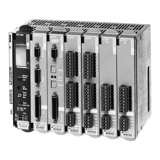
- Page 3 Antriebs- und Steuerungstechnik CL200 CL200 Manual Edition...
- Page 4 Manual 1070 072 145-102 (01.07) GB E 1995 – 2001 by Robert Bosch GmbH, Erbach / Germany All rights reserved, including applications for protective rights. Reproduction or distribution by any means subject to our prior written permission. Discretionary charge 20.– DM...
-
Page 5: Table Of Contents
......... . 2–4 CL200 Specifications ........ - Page 6 Contents Digital Output Modules ......7–1 Features and Functions ........7–1 Connections and Settings .
- Page 7 ......17–11 17.3.4 EMC Characteristics of the CL200 ......17–11 17.3.5...
- Page 8 Contents VIII Notes: 1070 072 145-102 (01.07) GB...
-
Page 9: Safety Instructions
Safety Instructions 1–1 Safety Instructions Before you start working with the CL200 Controller, we recommend that you thoroughly familiarize yourself with the contents of this manual. Keep this manual in a place where it is always accessible to all users. -
Page 10: Qualified Personnel
Safety Instructions 1–2 Qualified personnel This instruction manual is designed for specially trained personnel. The rele- vant requirements are based on the job specifications as outlined by the ZVEI and VDMA professional associations in Germany. Please refer to the following German-Language publication: Weiterbildung in der Automatisierungstechnik Publishers: ZVEI and VDMA Maschinenbau Verlag Postfach 71 08 64... -
Page 11: Safety Markings On Components
Safety Instructions 1–3 Safety markings on components DANGER! High voltage! DANGER! Corrosive battery acid! CAUTION! Electrostatically sensitive devices (ESD)! Disconnect mains power before opening! Lug for connecting PE conductor only! Functional earthing or low-noise earth only! Screened conductor only! 1070 072 145-102 (01.07) GB... -
Page 12: Safety Instructions In This Manual
Safety Instructions 1–4 Safety instructions in this manual DANGEROUS ELECTRICAL VOLTAGE This symbol warns of the presence of a dangerous electrical voltage. In- sufficient of lacking compliance with this warning can result in personal injury. DANGER This symbol is used wherever insufficient or lacking observance of this in- struction can result in personal injury. -
Page 13: Safety Instructions For The Described Product
The consequences may be severe personal injury or damage to equipment or the environment. Therefore, any system retrofitting or modification utilizing equipment components from other manufac- turers will require express approval by Bosch. DANGEROUS ELECTRICAL VOLTAGE Unless described otherwise, maintenance procedures must always be carried out only while the system is isolated from the power sup- ply. - Page 14 Safety Instructions 1–6 CAUTION Danger to the module! All ESD protection measures must be observed when using the mo- dule! Prevent electrostatic discharges! Observe the following protective measures for electrostatically sensitive de- vices (ESD)! D The personnel responsible for storage, transport and handling must be trained in ESD protection.
-
Page 15: Documentation, Software Release And Trademarks
– – Trademarks All trademarks referring to software that is installed on Bosch products when shipped from the factory represent the property of their respective owners. At the time of shipment from the factory, all installed software is protected by copyright. - Page 16 Safety Instructions 1–8 The UL Mark is a registered certification mark of Underwriters Laboratories, Inc., an independent, not-for-profit product safety testing and certification or- ganization. 1070 072 145-102 (01.07) GB...
-
Page 17: System Introduction
2–1 System Introduction Features and Functions The CL200 is a powerful controller system of compact and modular design. Application areas In its minimum configuration, the CL200 facilitates cost efficient deployment even in the smallest machine compounds. When fully configured with all available options or deployed as a decentralized controller in a networked situation, it can handle partial tasks in transfer lines. - Page 18 System Introduction 2–2 Performance range With 7 different central processing units, the CL200 allows accurate fine–tu- ning of the controller performance to task related requirements. D ZE200 Cost effective variant for small and high-speed controller tasks. D 2 high-speed 32-bit counters...
-
Page 19: Ul-Certification
System Introduction 2–3 2.1.1 UL-Certification The CL200 hardware modules are Underwriters Laboratories (UL) certified for operation in the United States and Canada. The modules are listed in the “Product Identity 17YB”. Designation Order no. Described in Input module w/ spring loa-... -
Page 20: Programming
System Introduction 2–4 Programming The CL200 is programmed with the aid of a PC via the serial COM port. With the use of the PC, the PLC program can also be written without requi- ring the physical presence of the controller. -
Page 21: Cl200 Specifications
Operating with the MemoryCard requires additional obser- vation of the operating conditions issued by the manufacturer. The CL200 controller is a Class A device. It is designated for deploy- ment in an industrial setting. When operated in private residences, in business or small-industry settings, the CL200 may cause radio inter- ference. - Page 22 System Introduction 2–6 Specifications CL200 D Line transient interference D Rapid burst pulses, symm., D 2 kV for power supply module and as per EN 61131-2 digital inputs/outputs D 1 kV for analog inputs / outputs, counter and interrupt inputs, serial...
-
Page 23: Module Slots
System Introduction 2–7 Specifications CL200 Weight, GG3 module rack D Net weight, 1kg D Fully populated, approx. 3 kg Weight, GG3-K module rack D Net weight, 0.58 kg D Fully populated, approx. 1.8 kg Dimensions, GG3 , w/ population 224 x 184 x 126... - Page 24 System Introduction 2–8 Notes: 1070 072 145-102 (01.07) GB...
-
Page 25: Module Racks
Module Racks 3–1 Module Racks Overview For the basic and expansion units, the following module racks are available: D GG3 w/ 7 module slots D GG3-K w/ 4 module slots Both module racks consist of a metal housing. The modules are inserted into the slot guide rails inside the module rack and then pressed home until properly seated. -
Page 26: Assembly
Module Racks 3–2 Assembly Hole for joining two module GG3 K : racks w/ mounting screws 223.5 Locking foot 125.9 Hole for joining two module racks w/ mounting screws The module racks GG3 and GG3-K are suitable for installation in a control cabinet meeting IP54 protection category requirements. - Page 27 Module Racks 3–3 Clear space Clear space 100 + cable Clear space channel 45 + cable channel 45 + cable channel 100 + cable- 100 + cable channel channel [Dimensions in mm] Installation The GG3 / GG3-K module rack can be secured in one of the following ways: D Screw mounted surface installation D Installation via locking foot, and insertion in 35 x 7.5 mm support rail, as per EN 50022.
- Page 28 Module Racks 3–4 Installation using locking foot Î Î Î Î Î Î Î Î Î Î Î Î Î Î Î Install locking foot w/ M4 x 8Z3 Locking foot combination screws 1070 072 145-102 (01.07) GB...
-
Page 29: Basic Unit
Module Racks 3–5 Basic Unit In its minimum configuration, the basic unit consists of: D GG3 or GG3-K module rack D NT200 power supply module D Central processing unit The remaining module slots can be used for D Digital input / output modules D Analog modules D Intelligent modules (R200, R200P, COM2E) D Max. -
Page 30: Expansion Unit
When planning an expansion, the maximum address range and the current draw of the controller must always be observed. The CL200 can be expanded very easily to accommodate additional modu- les. The GG3 or GG3-K module rack is used as an expansion unit. - Page 31 Module Racks 3–7 Ordering information Designation Order no. GG3 Module rack 1070 075 100 GG3-K Module rack 1070 079 961 Locking foot for support rail 1070 077 225 Bus coupler 1070 075 110 AG/S Expansion module 1070 075 916 AG/S Connecting cable, 0.3 m 1070 077 162 Dummy cover 1070 075 174...
-
Page 32: Expansion Structure
Module Racks 3–8 3.4.1 Expansion Structure Horizontal installation, inline One inline row of modules consists of max. 2 module GG3 or GG3-K module racks; alternatively, it may comprise one GG3 plus one GG-K module rack. This expansion unit is mounted directly beside the basic unit (see diagram): When assembled side-by-side, two GG3 module racks conform to the 19-inch EIA standard. - Page 33 Module Racks 3–9 Assembling / installing module racks D Based on drilling template D On support rail, for multiple-row expansion GG3K : 58.6 GG3K : 58.6 : 150 : 150 36.75 73,5 Use bus coupler to establish bus connection between module racks. Ï...
- Page 34 D CPU and power supply module always installed at bottom left D AG/S must always be inserted in far end right hand module slot. The CL200 controller accommodates a maximum of three inline expan- sion rows. When using the AG/S, the maximum permissible distance between to mo- dule racks is 5 meters.
- Page 35 Module Racks 3–11 Surface mounted installation Clear space 100 + cable channel width w 250 + Cable channel width w 250 + Cable channel width 100 + Cable channel width Clear space The height of the cable channel should not exceed 65 mm. 1070 072 145-102 (01.07) GB...
- Page 36 Module Racks 3–12 Support rail installation Clear space 100 + Cable channel width w 250 + Cable channel width w 250 + Cable channel width 100 + Cable channel width Clear space The height of the cable channel should not exceed 65 mm. 1070 072 145-102 (01.07) GB...
- Page 37 Module Racks 3–13 Vertical module rack installation The vertical arrangement of the CL200 is permissible only in a single-row configuration. The following restrictions must be observed: D The maximum permitted configuration is two module racks. D CPU and power supply module always to occupy bottom slots.
- Page 38 Module Racks 3–14 Notes: 1070 072 145-102 (01.07) GB...
-
Page 39: Nt200 Power Supply Module
NT200 Power Supply Module 4–1 NT200 Power Supply Module Features and Functions The NT200 power supply module performs the following functions: D Provision of internal operating voltages: D 5 V for the central processing unit D 3.4 V memory backup battery voltage D 7.5 V for peripheral modules D 12 V ISO for 20 mA interface D Undervoltage monitoring of 24 V power supply... - Page 40 NT200 Power Supply Module 4–2 Module slot Basic unit 1 2 3 4 5 6 7 1 2 3 4 GG3-K DANGEROUS ELECTRICAL VOLTAGE Hazard to personnel! Operation of the NT200 power supply module generates voltage peaks which significantly exceed the functional extra low voltage. The module may be powered up only while inserted in the module rack.
-
Page 41: Display And Control Elements
NT200 Power Supply Module 4–3 Display and Control Elements Memory backup battery 24 V power supply connector Low Battery LED The Low Battery LED indicates battery failure. Battery Reset button The Battery Reset button performs two functions: D RESET and acknowledgement of a battery failure. D Activation of battery load test.If a fault is detected, the Low Battery war- ning signal S30.7 in the system area goes HIGH. - Page 42 NT200 Power Supply Module 4–4 PG Mode LED Refer to Chapter 5, Central Processing Unit, section 5.2, Display and Control Elements Copy / Stop / Run switch/button Refer to Chapter 5, Central Processing Unit, section 5.2, Display and Control Elements Stop LED Refer to Chapter 5,Central Processing Unit, section 5.2, Display and Control Elements...
-
Page 43: Memory Backup Battery
D Time interval for which the controller is switched off Replace the memory backup battery after 1!/$ years at the latest. The CL200 uses lithium backup batteries. They contain less than 0.5 g of lithium, and are hermetically sealed. They are not considered a hazardous substance when transported in their original package. - Page 44 NT200 Power Supply Module 4–6 Battery failure is indicated by the Low Battery LED, and the S27.2 battery fault bit goes HIGH. During RAM operation, when a fault has been detected in the backup bat- tery, the central processing unit remains in STOP mode, and the PLC pro- gram is deleted.
-
Page 45: Specifications
NT200 Power Supply Module 4–7 Remove old backup battery. This causes a battery warning to be indicated in the system area and on the programming device. Gently tap new backup battery on hard surface to break internal oxide layer. Ensuring correct polarity, insert new battery. Reinstall battery compartment cover, and push upward. - Page 46 NT200 Power Supply Module 4–8 Ordering information Designation Order no. NT200 Power supply module 1070 075 096 Memory backup battery 1070 917 152 1070 072 145-102 (01.07) GB...
-
Page 47: Central Processing Unit
Central Processing Unit 5–1 Central Processing Unit Features and Functions ZE200M ZE200 ZE200A ZE201 ZE200AM ZE200-DP ZE200A-DP 1070 072 145-102 (01.07) GB... - Page 48 D 2 organization modules for timer controlled functions D 3 organization modules for interrupt inputs D Fixation of inputs/outputs and markers The instruction set used with the CL200 is upward compatible for use with the CL400 and CL500 controllers. ZE200, ZE200A, ZE200M, ZE200AM, ZE201, ZE200-DP, ZE200A-DP...
- Page 49 Refer to section 5.4.2, “X71 Interrupt and High-speed Counter Inputs”. Interrupt inputs The central processing units of the CL200 feature three 24 V interrupt inputs. Refer to section 5.4.2, “X71 Interrupt and High-speed Counter Inputs”. Analog inputs and outputs The analog output can supply a current or voltage rated signal.
- Page 50 Central Processing Unit 5–4 Second serial interface The ZE201 provides a second serial interface with additional transmission protocols. COMNET-DP interface The ZE200-DP and ZE200A-DP feature a PROFIBUS-DP interface (mar- ked “COMNET-DP” on the module) for field bus connection. Module slot CAUTION Do not insert or remove the module while the controller is switched ON! This may destroy the module.
-
Page 51: Display And Control Elements
Central Processing Unit 5–5 Display and Control Elements The display and control elements for the central processing units are located on the NT200 power supply module. The ZE200-DP features two additional status LEDs and one Send LED to monitor the operation of the PROFIBUS- DP interface. - Page 52 Copy function: D Stop mode D Run mode D Copy procedure: – at Power-ON – during standard operation Refer also to order no. for “CL200 Operations List”, in section 1.6, chapter “Memory Management”. 1070 072 145-102 (01.07) GB...
- Page 53 Central Processing Unit 5–7 Status 1 LED Status 2 LED on ZE200-DP and ZE200A-DP The Status 1 and Status 2 LEDs indicate the following operating statuses of the PROFIBUS-DP interface, and of the ZE200-DP and ZE200A-DP central processing units. Status 1 Status 2 LED display Explanation...
- Page 54 Central Processing Unit 5–8 Send LED The Send LED indicates a data transmission in progress. Reset DP pushbutton The Reset DP pushbutton can be used to reset the DP bus master in the cause of an error. During Power-ON of the supply voltage, pressing the Reset DP pushbutton and holding it until the LED test has ended causes the PROFIBUS-DP confi- guration to be deleted.
-
Page 55: Memorycard
Central Processing Unit 5–9 MemoryCard The ZE200M and ZE200AM central processing units feature a card slot for the MemoryCard. The MemoryCard is used to load and back up the PLC pro- gram. The ZE200M and ZE200AM are equipped with a PCMCIA (”PC card”) inter- face, version 2.01, and Type 1 card slot for access times in excess of 200 ns. -
Page 56: Interfaces
Interfaces 5.4.1 Interface Connections All interface interconnections on the CL200 central processing unit are ac- complished via D-sub plug connectors. Connections must use screened ca- bles. Almost without exception, interface connectivity entails the interconnecting of cables inbound from a variety of locations. This is accom- plished with the use of industry standard adapter elements. -
Page 57: X71 Interrupt And High-Speed Counter Inputs
Central Processing Unit 5–11 5.4.2 X71 Interrupt and High-speed Counter Inputs Refer also to “CL200 Operations List”, order no. in section 1.6. The interrupt inputs and high-speed counters are connected via the female DB-9 connector of the X71 interface. Pin assignment: Pin no. - Page 58 LOW signal 0 mA 5 mA 10 mA 15 mA Interrupt inputs The CL200 central processing units provide three 24 V interrupt inputs. Specifications Interrupt inputs Inputs, as per EN 61131-2 3 digital inputs, Type 1 Rated voltage 24 VDC...
- Page 59 Central Processing Unit 5–13 High-speed counters Two mutually independent 32-bit forward and reverse counters are availa- ble. Each counter has two limit values. Counter inputs are not electrically isolated. Specifications High-speed counters Quantity 2, 32-bit counters Rated voltage 24 VDC Input voltage D LOW signal –3 to +5 V...
- Page 60 Central Processing Unit 5–14 High-speed counters (ROD application) The following peripheral conditions apply to operation with incremental ro- tary transducers: D The function is available for counter 1 only. D The new mode is enabled by setting the MSB in word 20 of the OM2 orga- nization module to HIGH.
-
Page 61: X72 Analog Inputs And Outputs
5.4.3 X72 Analog Inputs and Outputs Refer also to “CL200 Operations List”, order no. in section 1.6. The ZE200A, ZE200AM, and ZE200A-DP central processing units are the only ones providing 4 analog inputs plus one analog output. They are con- nected via the X72 female DB-15 connector. - Page 62 Central Processing Unit 5–16 Specifications Analog inputs Analog inputs, 4 power inputs as per EN 61131-2 Input voltage range D 0 to 10 V, unipolar D Selectable between 2 and 10 V Input resistance 20 kW Protective circuit RC circuit, Schottky diodes Max.
- Page 63 Central Processing Unit 5–17 Analog output The analog output is a short-circuit protected current or voltage rated power output. The analog output is not electrically isolated. An additional external power supply is not required. Example of connection diagram: RLV w 1000 W RLI v 600 W When switching the controller power supply ON or OFF, the analog output provides an output value of 0 (zero).
- Page 64 Central Processing Unit 5–18 Specifications Analog output Analog output, as per EN 61131-2 Power output, voltage rated D Voltage range D 0 to 10 V D Standardizable to between 2 and 10 V via OM2 D Load resistance w 1 kW D Short-circuit current 32 mA Power output, current rated...
-
Page 65: X31 Interface For Pg Programming Unit
Central Processing Unit 5–19 5.4.4 X31 Interface for PG Programming Unit The X31 is a combination V.24 / 20 mA interface in accordance with VDI Gui- deline VDI 2880, Page 2. The X31 female DB-25 connector accepts the PG programming unit or an- other peripheral device, such as the BT20 control panel, for example. - Page 66 Central Processing Unit 5–20 Transmission protocol The following transmission protocol is permanently set: D Even parity D 1 Stop bit D 8 Data bits There are no control lines. V.24 interface As the V.24 interface is not electrically isolated from logic circuits and power supply, this may on rare occasions connectivity problems with devices whose interface also lacks electrical isolation.
- Page 67 Central Processing Unit 5–21 Pin assignment, female DB-25 connector (active): Signal designation Signal function Housing Screen Screening 12 V out 12 V out 12 V in 12 V in 12 V GND 12 V reference conductor RXD+ Receive data + RXD–...
-
Page 68: X32 Second Serial Interface
Central Processing Unit 5–22 5.4.5 X32 Second Serial Interface This V.24 interface on the ZE201 utilizes a female DB-9 connector and is compatible with the COM port on a PC. For example, in the event that a con- trol terminal is connected to X31, this second serial interface can be used to connect the programming unit. - Page 69 Central Processing Unit 5–23 Limitation With the operation of the second serial interface, a response time on the in- terrupt inputs that is shorter than 1 ms can no longer be guaranteed. Connecting cable Do not route data lines parallel to power lines. A premanufactured connecting cable is available to connect to the X32 inter- face connector: Designation...
-
Page 70: X73 Profibus-Dp Interface
Central Processing Unit 5–24 5.4.6 X73 PROFIBUS-DP Interface The PROFIBUS-DP interface on the ZE200-DP and ZE200A-DP comprises an electrically isolated RS-485 interface and conforms to the EN 50170-2 standard. All components are designed for a baud rate of 12 Mbaud. The X73 connector is a female DB-9. - Page 71 Central Processing Unit 5–25 PLC cycle time With regard to PLC cycle time on the ZE200-DP and ZE200A-DP, the follo- wing shall be observed: D For each 256 bytes of decentrally assigned I/O, the I/O state shifts by ap- prox. 1 ms. D In the case of diagnostic data processing or transmission problems on the DP bus, a max.
- Page 72 Central Processing Unit 5–26 The maximum permissible cable length depends on the cable type used, the transmission rate and installed repeaters: Baud rate [Baud] Length in m up to 93.75 12000 187.5 1000 1500 3000 6000 12000 D The above length information presupposes the use of cable type A (as per EN50170-2) with appropriate bus terminating resistors.
-
Page 73: Operating Modes
Central Processing Unit 5–27 Operating modes The central processing units of the CL200 feature 2 internal memory sec- tions for the PLC program. D RAM D Flash-EPROM memory Besides the purely RAM or Flash-EPROM operation of the CL200, mixed operation is also possible (doubled memory capacity). -
Page 74: Reloading The Firmware
Central Processing Unit 5–28 Reloading the Firmware The firmware onboard the central processing units can be reloaded. The re- loading / updating procedures are described in the README file supplied with the software. 1070 072 145-102 (01.07) GB... -
Page 75: Specifications
Central Processing Unit 5–29 Specifications Specifications ZE200 ZE201 ZE200A ZE200M ZE200AM ZE200-DP ZE200A-DP Program memory 128 kbytes RAM and 128 kbytes Flash-EPROM System clock Analog inputs / outputs High-speed counters 2 x 32 bit counters or 1 x connection for incremental rotary transducer (ROD; not ZE200-DP and ZE200A-DP) Interrupt inputs MemoryCard slots Serial interfaces... - Page 76 Central Processing Unit 5–30 Specifications ZE200 ZE201 ZE200A ZE200M ZE200AM ZE200-DP ZE200A-DP Current draw from D 5 V Typically 200 mA Typically 250 mA Typ. Typ. for central processing unit 650 mA 675 mA D Memory backup battery Typically 6 mA D 7.5 V Typically 1.5 mA for peripheral modules...
-
Page 77: 24 V- Digital Input Modules
E 24 V– (16-way) E 24 V– (32-way) The E 24 V– digital input modules for the CL200 provide 16 or 32 digital in- puts in accordance with Type 1 of the EN 61131-2 standard. The process signals are electrically isolated from internal logic circuits by means of optocouplers. - Page 78 E 24 V– Digital Input Modules 6–2 Modul slots GG3-K Expansion unit 1 2 3 4 5 6 7 GG3-K Basic unit 1 2 3 4 5 6 7 CAUTION Do not insert or remove the module while the controller is switched ON! This may destroy the module.
-
Page 79: Connection
E 24 V– Digital Input Modules 6–3 Connection All of the 16 or 32 inputs have common 24 V and 0 V potential. An input can be connected to an output of the output modules without addi- tional load. Connection via push-lock terminals: D max. - Page 80 E 24 V– Digital Input Modules 6–4 V / I characteristic curve, as per EN 61131-2 30 V HIGH signal 20 V Actual 10 V Switchover range switchover range LOW signal 0 mA 5 mA 10 mA 15 mA Addressing A start address must be set for each module on the S1 DIP switch (example below is for an E 24 V–, 32-way): S1 DIP switch...
-
Page 81: Specifications
E 24 V– Digital Input Modules 6–5 Specifications Specifications E 24 V– (16-way) E 24 V– (32-way) Inputs, as per 16 digital inputs, Type 1 32 digital inputs, Type 1 EN 61131-2 Internal current draw 25 mA 45 mA from D NT200 (7.5 V) D RM2-DP12 (7.5 V) Isolated potential... - Page 82 E 24 V– Digital Input Modules 6–6 Notes: 1070 072 145-102 (01.07) GB...
-
Page 83: Digital Output Modules
Digital Output Modules 7–1 Digital Output Modules A24V–/2A A24V–/0.5A 32–way A24V–/0.5A 16–way AR/2A Features and Functions Construction The digital output modules handle a nominal current of 0.5 A or 2 A. The output signals are electrically isolated from the process signals via opto- couplers. -
Page 84: Connections And Settings
Digital Output Modules 7–2 A24V– module slots Expansion unit Basic unit GG3-K GG3-K 1 2 3 4 5 6 7 1 2 3 4 5 6 7 CAUTION Do not insert or remove the module while the controller is switched ON! This may destroy the module. - Page 85 Digital Output Modules 7–3 Power circuit A Power circuit B Using a suitable tool, extract fuse F1 or F2 from socket, then insert new 3.0 A FF fuse. The fuse is supplied complete with fuse holder. Insert module in module rack, and push home firmly. Reconnect push-lock terminals.
- Page 86 Digital Output Modules 7–4 The 8-segment S1 DIP switch is used to select between output (O) and ex- tended output field (EO). Switch Weighting Value O= OFF EO= ON Connection D Polarity reversal of the 24 V power supply along with a simultaneous short-circuit on one of the outputs will destroy the module.
-
Page 87: A 24 V- Output Module / 0.5 A (16-Way And 32-Way)
Digital Output Modules 7–5 A 24 V– Output Module / 0.5 A (16-way and 32-way) The general conditions and specifications appearing in section 7.1 apply. Function The outputs are short-circuit protected. The electronic short-circuit protec- tion is triggered by a current of typically 1.2 A. Due to thermal load considera- tions, output loads must not exceed the rated 0.5 A current. - Page 88 Digital Output Modules 7–6 There is no electrical connection between the A-outputs and B-outputs on the module. With the prerequisite of having two separate power supplies, this facilitates the separate shutdown of the supply voltage for the A-outputs while the B-outputs remain functional (in an “Emergency–STOP” situation, for example).
-
Page 89: A 24 V- / 2 A Output Module
Digital Output Modules 7–7 A 24 V– / 2 A Output Module The general conditions and specifications appearing in section 7.1 apply. Function The outputs are short-circuit protected. The electronic short-circuit protec- tion is triggered by a current of typically 2.4 A. Due to thermal load considera- tions, output loads must not exceed the rated 2 A current. - Page 90 Digital Output Modules 7–8 Features The AR/2A output module provides 8 floating contact assemblies for a rated current of 2 A. The AR/2A meets the requirements of Protective Separation for overvoltage class (ÜK) II, as per EN 50178. Voltages belonging to over- voltage class III may be connected on a given 4-conductor terminal only pro- vided that voltage potentials are effectively separated by a vacant terminal between connections.
- Page 91 Digital Output Modules 7–9 Function Upon switching off inductive loads, the outputs are not connected electroni- cally but via varistors. The voltage peaks are limited to typically 300 V. CAUTION Relay overloading causes damage to switching contact points which can be remedied only through relay replacement. The user is called upon to provide circuit fusing in accordance with rated loads.
-
Page 92: Specifications
Digital Output Modules 7–10 Specifications Specifications A 24 V– / 0.5 A A 24 V– / 0.5 A A 24 V– / 2 A AR/2 A (32-way) (16-way) Outputs as per EN 61131-2 32 digital outputs, 16 digital outputs, 8 digital outputs, 8 floating relay out- 2 times 16 semi- 2 times 8 semicon-... - Page 93 Digital Output Modules 7–11 Specifications A 24 V– / 0.5 A A 24 V– / 0.5 A A 24 V– / 2 A AR/2 A (32-way) (16-way) Push-lock terminals Max. cable cross-section 1.5 mm@ Max. terminal current Cable length max. 200 m, max.
- Page 94 Digital Output Modules 7–12 **) A simultaneity (diversity) of 75 % and/or a total current of 6 A applies to multi-row configurations (without limitation of simultaneity or total current as compared to a single-row configuration). Ordering information Designation Order no. Output module w/ spring-loaded terminals 1070 083 385...
-
Page 95: Digital Input/Output Modules
Digital Input/Output Modules 8–1 Digital Input/Output Modules Functions and Features E16/A16, 0.5 A E16/A8, 0.5 A Both input/output modules provide 16 digital inputs each, and 8 and 16 digi- tal outputs, respectively. The rated current for each input or output is 0.5 A. Both input and output signals are electrically isolated from the logic circuits via optocouplers. - Page 96 Digital Input/Output Modules 8–2 Module slots GG3-K Expansion unit 1 2 3 4 5 6 7 GG3-K Basic unit 1 2 3 4 5 6 7 CAUTION Do not insert or remove the module while the controller is switched ON! This may destroy the module. Prior to inserting or removing the module, ensure that module is not energized! CAUTION Do not insert or remove the module while there is power applied (to...
-
Page 97: Addressing
Digital Input/Output Modules 8–3 Addressing Each of the two input/output module variants always occupies 2 bytes inputs and 2 bytes outputs in the PLC address field. A start address for each module must be set on the S1 DIP switch: S1 DIP switch S1 Start address The 8-segment S1 DIP switch is used to select between input (I) and output... -
Page 98: Connection
Digital Input/Output Modules 8–4 Connection Connection via push-lock terminals: D Max. cable cross-section : 1,5 mm@ D Max. terminal current D Polarity reversal of the 24 V power supply along with a simultaneous short-circuit on one of the outputs will destroy the module D Polarity reversal of the 24 V power supply along with the connection of diode-type fuses with rated voltages below 30 V may destroy the module. - Page 99 Digital Input/Output Modules 8–5 The following cannot be connected: D 2-wire proximity switches that largely exploit the IEC 947-5-2 standard. D 2-wire proximity switches (NAMUR standard). Input circuit diagram Input characteristic U [V] HIGH signal Switchover range LOW signal I [mA] 1070 072 145-102 (01.07) GB...
-
Page 100: X11B, X12B Outputs
Digital Input/Output Modules 8–6 8.3.3 X11B, X12B Outputs All outputs share a common 24 V and 0 V potential. Thanks to the low leakage current of 0.5 A, an output can be connected to an input. The outputs are protected against short-circuit and overtemperature. A cur- rent in excess of 0.6 A triggers the electronic monitor, switching off only the faulty output. - Page 101 Digital Input/Output Modules 8–7 For more detailed information, consult the following publication (German-language): Handbuch zur Entstörung von geschalteten Induktivitäten (Manual: “Interference suppression in switched inductances”) Available from: Friedrich Lütze GmbH & Co Abteilung Marketing Bruckwiesenstraße 17 - 19 D-71384 Weinstadt (Großheppach) Germany 1070 072 145-102 (01.07) GB...
-
Page 102: Specifications
Digital Input/Output Modules 8–8 Specifications Specifications E16/A16- 0.5 A E16/A8- 0.5 A Power supply external 24 VDC (19.2...30 V) Current draw from D PLC power supply NT200 (7.5 V) 25 mA + 1.5 mA per enabled output + 0,5 mA per enabled input D 24 V power supply 12 mA at idle 8 mA at idle... - Page 103 Digital Input/Output Modules 8–9 Specifications E16/A16- 0.5 A E16/A8- 0.5 A Output rise time TQT D LOW ³ HIGH 50 ms D HIGH ³ LOW 10 ms Contactor size 6.2 W Push-lock terminals Max. cable cross-section 1.5 mm@ Max. terminal current Cable length 200 m unscreened, 300 m screened Width...
- Page 104 Digital Input/Output Modules 8–10 Notes: 1070 072 145-102 (01.07) GB...
-
Page 105: Dp-Ea4 Peripheral Bus Station Module
The module is addressed on the peripheral bus of the controller just like any standard digital input / output module. Once the CL200 has been powered up (7.5 V peripheral bus), the module performs an automatic startup routine and then awaits initialization of the DP-Master. - Page 106 DP-EA4 Peripheral Bus Station Module 9–2 The DP-EA4 peripheral bus station module provides 4 bytes for inputs (from the vantage point of the PROFIBUS-DP Master, these are the outputs of the slave), and 4 bytes for inputs (from the vantage point of the PROFIBUS-DP Master, these are the inputs of the slave).
-
Page 107: Display And Control Elements, Connections And Settings
DP-EA4 Peripheral Bus Station Module 9–3 Display and Control Elements, Connections and Settings Diagnostics The “Stop” LED indicates the operating status of the DP ring. D LED extinguished: Normal operating status D LED illuminates: Fault in DP operation Pressing the RESET button triggers a hardware RESET. The module will subsequently attempt to reestablish a new DP connection. - Page 108 DP-EA4 Peripheral Bus Station Module 9–4 S2 switch Weighting Value E/A=OFF EI/EO=ON Consistency setting Jumper JP3 is useed to select consistent or non-consistent data transmis- sion (Consistency / No Consistency). The selected operating mode must also be approriately set in the DP master configuration.
-
Page 109: Specifications
DP-EA4 Peripheral Bus Station Module 9–5 Specifications Specifications DP-EA4 Inputs 4 bytes Outputs 4 bytes External power supply None Power supply 7.5 V from NT200 PLC power supply Current draw typ. 270 mA + max. 120 mA for RS-485 interface Interfaces PROFIBUS-DP w/ RS-485 Isolated potential... - Page 110 DP-EA4 Peripheral Bus Station Module 9–6 Notizen: 1070 072 145-102 (01.07) GB...
-
Page 111: Ag/S Expansion Module
AG/S Expansion Module 10–1 AG/S Expansion Module 10.1 Features and Functions The AG/S expansion module facilitates an expansion of the controller to more than two module racks, or to configure multi-row arrangements. The connection must always start at the basic unit (row), and progress from there to the expansion rows. - Page 112 Connecting modules must be inserted and connected only while deenergized. Maximum expansion The maximum permitted expansion for the entire CL200 comprises 3 rows. When using the AG/S, the distance between two module racks may be up to 5 m. 1070 072 145-102 (01.07) GB...
-
Page 113: Specifications
AG/S Expansion Module 10–3 10.2 Specifications Specifications AG/S Internal current draw from NT200 typ. 15 mA (7.5 V) max. 40 mA Insulation test 500 VDC Connecting cable max. 5 m Width 1 slot Weight 160 g Ordering information Designation Order no. AG/S Expansion module 1070 075 916 K18 Connecting cable, 27 x 0.14 mm@, 0.3 m... - Page 114 AG/S Expansion Module 10–4 Notizen: 1070 072 145-102 (01.07) GB...
-
Page 115: R200, R200P, Com2-E Communication Modules
R200, R200P, COM2-E Communication Modules 11–1 R200, R200P, COM2-E Communication Modules 11.1 Functions and Features R200 R200P COM2–E 1070 072 145-102 (01.07) GB... -
Page 116: R200 Communication Module
11.1.1 R200 Communication Module The R200 communication module comprises one of the CL200 system mo- dules. It is used to connect the CL200 to other Bosch control units and other types of intelligent devices. Interfaces The R200 provides two interfaces: D V.24 interface... -
Page 117: R200P Communication Module
1070 077 901) in the PLC program will be required. 11.1.2 R200P Communication Module The R200P communication module comprises the PROFIBUS-FMS con- nection for the CL200. It provides the controller with an extensive variety of networking and communications options via the PROFIBUS-FMS. Interfaces The R200P provides two interfaces: D PROFIBUS-FMS interface D V.24 / 20mA combination interface... -
Page 118: Com2-E Communication Module
COM2-E Communication Module The COM2-E communication module comprises one of the CL200 system modules. It is used to connect the CL200 to other Bosch control units and other types of intelligent devices. The COM2-E can also be used in combina- tion with the R200 and R200P in the basic unit of the CL200 controller. - Page 119 The BUEP64 protocol is used to handle the data exchange between com- plex or spatially distributed controller systems. Connectivity options On the basis of the listed transmission protocols, the COM2-E provides the following connectivity options: D Computer (PC, host computer, etc.) D CL150, CL200, CL400, CL500 1070 072 145-102 (01.07) GB...
-
Page 120: Specifications
R200, R200P, COM2-E Communication Modules 11–6 D Scanner D Printer Module slots 1 2 3 4 5 6 7 GG3-K Basic unit Ethernet address / IP address Each COM2-E module comes with its own unique Ethernet address. This address is unique in the world, and should not be changed. In addition, to address the module via the Ethernet, an Internet address (IP address) is re- quired. -
Page 121: Advanced Documentation
R200, R200P, COM2-E Communication Modules 11–7 11.3 Advanced Documentation The following manuals are available for the communication modules: Manual German, order no. English, order no. R200 1070 072 400 1070 072 157 R200P 1070 072 401 1070 072 162 1070 072 145-102 (01.07) GB... - Page 122 R200, R200P, COM2-E Communication Modules 11–8 Notizen: 1070 072 145-102 (01.07) GB...
-
Page 123: Analog Input Modules
Analog Input Modules 12–1 Analog Input Modules 12.1 Features and Functions E20 ana E ana The analog input modules facilitate the preparation of analog process si- gnals for subsequent handling by the CL200. 1070 072 145-102 (01.07) GB... -
Page 124: E Ana Analog Input Module
4, 3 or 2-wire connections. Byte assignment The E ana occupies 4 input and 4 output bytes in the EI / EO address range of the CL200. Signal sources are connected via push-lock terminals. The input module requires an external 24 V power supply. -
Page 125: E20 Ana Analog Input Module
D Sensor failure detection in 4 through 20 mA measuring range Byte assignment The E20 ana occupies 4 input and 4 output bytes in the EI / EO address range of the CL200. Signal sources are connected via push-lock terminals. The input module requires an external 24 V power supply. -
Page 126: Advanced Documentation
Analog Input Modules 12–4 Suitable module slots 1 2 3 4 5 6 7 1 2 3 4 5 6 7 Basic unit Expansion unit 12.3 Advanced Documentation the following manuals are available for analog input modules: Manual German, Order no. English, Order no. -
Page 127: Analog Output Modules
Analog Output Modules 13–1 Analog Output Modules 13.1 Features and Functions A10 ana A ana A10 ana A20 ana (8 output) (4 output) The analog output modules provide control outputs for analog process data signals. Module variants The analog output module is available in four variants: D A ana w/ 2 analog outputs D A10 ana w/ 4 analog power outputs, voltage rated 1070 072 145-102 (01.07) GB... -
Page 128: A Ana Analog Output Module
The output module requires an external 24 V power supply. 13.1.2 A10 ana Analog Output Module The A10 ana output module for the CL200 features 4 or 8 analog voltage ra- ted power outputs. The A10 ana module provides: D 12-bit resolution D Voltage range, 0 through 10 V Actuators are connected via push-lock terminals. -
Page 129: Specifications
Analog Output Modules 13–3 Actuators are connected via push-lock terminals. The output module requires an external 24 V power supply. 13.2 Specifications Specifications A ana A10 ana (4 outputs) A10 ana (8 outputs) A20 ana Order no. 1070 077 138 1070 078 507 1070 078 295 1070 078 914... -
Page 130: Advanced Documentation
Analog Output Modules 13–4 13.3 Advanced Documentation The following manuals are available for analog output modules: Manual German, Order no. English, Order no. A ana, A10 ana 1070 072 409 1070 072 165 1070 072 145-102 (01.07) GB... -
Page 131: Positioning Modules
Positioning Modules 14–1 Positioning Modules 14.1 Features and Function Module variants To handle positioning tasks, several modules – some with special features – are available: D Counting / Positioning modules POS-SA1 (1 channel) and POS-SA2 (2 channels) D Positioning module POS-LR1 (1 channel) and POS-LR2 (2 channels) POS–SA2 POS–SA1 1070 072 145-102 (01.07) GB... -
Page 132: Pos-Sa1 And Pos-Sa2 Counting / Positioning Modules
Positioning Modules 14–2 POS-LR1 POS-LR2 14.1.1 POS-SA1 and POS-SA2 counting / positioning modules Module variants Two modules are available to provide counting / positioning functions, and to handle simple positioning tasks: D POS-SA1, w/ 1 channel D POS-SA2, w/ 2 channels Module tasks The modules handle the following tasks: D Counting... -
Page 133: Pos-Lr1 And Pos-Lr2 Positioning Modules
Positioning Modules 14–3 D Position sensing D Positioning w/ interrupting axis The modules facilitate the connection of incremental or absolute measuring / encoder systems. POS-SA1 The POS-SA1 module features: D 1 channel w/ selectable encoder system D 4 digital inputs D 4 digital outputs POS-SA2 The POS-SA2 module features:... -
Page 134: Specifications
Positioning Modules 14–4 D Monitoring cable breaks via differential signals D Hardware and software limit switches 14.2 Specifications Specifications POS-LR1 POS-LR2 POS-SA1 POS-SA2 Order no. 1070 078 529 1070 078 533 1070 077 100 1070 077 103 Channels Encoder systems D Incremental max. -
Page 135: Bm2-Asi Bus Master
BM2-ASI Bus Master 15.1 Features and Functions The BM2-ASI module comprises the AS-I bus master for the CL200. It thus provides the CL200 with the cost effective options of decentralized input / output connection via AS-I. AS-I utilizes a simple 2-wire cable in a tree structure to replace the traditio- nal, elaborate parallel wiring of each individual input / output. -
Page 136: Specifications
BM2-ASI Bus Master 15–2 Tasks The BM2-ASI bus master module handles the following tasks: D Cyclical data exchange between bus station and central processing unit D Network initialization D Assignment of parameters to bus stations D Data transmission diagnostics D Addressing of substituted bus stations AS-I profiles The BM2-ASI module supports the following AS-I profiles: D M0, serving inputs / outputs only... -
Page 137: Rm2-Dp12 Module
PROFIBUS-DP. The RM2-DP12 module can be inserted in a CL200 module rack. It is powe- red by a 24 V power supply, and also provides the 7.5 V power (max. 1.2 A) for the input and output modules. -
Page 138: Connecting To Profibus-Dp
RM2-DP12 Module 16–2 The module uses single modular width. 16.2 Connecting to PROFIBUS-DP The RM2-DP is connected to the PROFIBUS by means of a male DB-9 con- nector which, for security reasons, should be screwed tightly onto the female DB-9 connector of the RM2-DP12. The X71 PROFIBUS connector is located on the front panel. -
Page 139: Display And Control Elements
RM2-DP12 Module 16–3 Selecting bus address A separate bus address must be assigned to each station on the PROFI- BUS-DP. The module bus address is set with the S1 DIP switch: S1 DIP switch start address The selected bus address is queried only during the startup sequence, i.e., once supply power has been applied terminal X10. -
Page 140: Specifications
RM2-DP12 Module 16–4 16.4 Specifications Specifications RM2–DP12 module Power supply, as per EN 61131-2 24 VDC, 19.2 to 30 V Bridging capability, intermittents on power Class PS2 v10 ms, supply module, as per EN 61131-2 Repetition rate w 1 s Current draw from 24 V power supply 1.35 A (rated current)) -
Page 141: Installation
17.1 External Power Supply All components of the CL200 are powered by a 24 V power supply. The power supply must feature protective separation in accordance with EN 50178, section 5.2.18.1. Transformers featuring protective separation must be constructed to EN 60742. -
Page 142: Power Supply
In this case, a power supply will be adequate to power the CL200. However, to meet the requirements of overvoltage category II, the use of an autotrans- former is not permitted. -
Page 143: Hardware Configuration W/ Electrical Isolation
Installation 17–3 17.2.2 Hardware Configuration w/ Electrical Isolation The provisions of DIN EN 60204-1 requires electrical isolation to exist bet- ween the logic circuits of the central processing unit and the I/O interfaces connecting the peripheral modules. As the NT200 power supply module is non-floating, the required electrical isolation can be achieved only by provi- ding a separate power supply unit for the NT200 on the one hand, and the peripherals on the other. -
Page 144: Reference Conductor Connected To Protective Earth
Installation 17–4 17.2.3 Reference Conductor Connected to Protective Earth If the reference conductor (N, 0 V) is interconnected with PE conductor net- work, this connection must centrally be located for easy accessibility (e.g., on the external power supply or isolating transformer). The connection must facilitate easy interruption, e.g., for the purpose of measuring earth leakage currents. -
Page 145: Reference Conductor Not Connected To Pe Conductor
In the majority of cases, programming units inherently feature a connection between (equipment) ground and protective earth. This connection gives rise to problems in situations where the power supply of the CL200 is equip- ped with an earth-leakage monitor and the programming unit is connected to the central processing unit. -
Page 146: Capacitive Load In Power Supply Network
Installation 17–6 17.2.6 Capacitive Load in Power Supply Network All CL200 modules contain capacitive interference suppression measures installed between the power supply lines and protective earth. This fact must be taken into account when employing an earth-leakage monitoring device. Module 24 V ³... -
Page 147: Dimensioning Power Cables
The input response time is 3 ms. If longer power interruptions occur, suitable measures must be introduced. 17.2.8 Master Switch A master switch conforming to VDE 0100 must be provided for the CL200, as well as for sensors and actuators. 17.2.9 Fuses The purpose of fuses and circuit breakers is to protect the cables in a power network. - Page 148 Installation 17–8 D External impedance / source impedance of network D Possible fault location D Vibration For further information, refer to the following (German–language) manual: Handbuch Nr. 32 VDE Schriftenreihe Bemessung und Schutz von Leitungen und Kabeln nach DIN 57 100, VDE 0100-430 und -523.
-
Page 149: Earthing
17.2.10 Earthing Functional earthing The GG3 and GG3-K module racks of the CL200 must be mounted on a me- tallic, earthed support, such as the rear panel of a control cabinet, for exam- ple. Functional earthing is required to provide optimum interference protection. -
Page 150: Electromagnetic Compatibility (Emc)
Installation 17–10 17.3 Electromagnetic Compatibility (EMC) Electromagnetic compatibility (EMC) is defined as the capability of an elec- trical device to function satisfactorily within its electromagnetic environment without unduly interfering with said environment in which other devices may also be accommodated (EN 61 000-4-1). 17.3.1 Interference To the user, possible sources of interference may include:... -
Page 151: Emc Directive And Ce Label
17.3.4 EMC Characteristics of the CL200 As a standalone unit, the CL200 already meets the EMC requirements ari- sing from the governing standards. Compliance with these standards was tested on specific system configura- tions. - Page 152 23 May 1997, published by the European Commission. Radiant emittances, radio interference The CL200 meets the requirements of the generic EN 50081-2 standard which defines the limit values for interference emissions. This standard ap- plies exclusively to application in industrial areas. In contrast to residential...
-
Page 153: Installation Procedures Ensuring Interference Resistance
Installation 17–13 17.3.5 Installation Procedures Ensuring Interference Resistance Without exception, priority shall always be given to the prevention or remedy or elimination of interference at the source. To this end, the following items must be observed: Earthing arrangements To eliminate interference potentials acting between the device and refe- rence earth, the housing must be connected to ground via a low-impedance connection. - Page 154 Filters In normal circumstances, the interference resistance of CL200 modules guarantees their proper functioning even in environments exhibiting relati- vely high interference levels. To further improve EMC characteristics, it may become necessary to introduce additional filtering measures.
-
Page 155: Index
E ana, 12–2 central processing unit, 2–2, 3–5, 4–4, 5–2 E20 ana, 12–3 chemical resistanc e, 2–6 earthing, 17–5, 17–9, 17–13 CL200, 2–5 earthing wrist strap, 1–6 clear space, 3–3, 3–11, 3–12, 3–13 electromagnetic compatibility, 17–10 COM2–E, 11–4 EMC characteristics, 17–11 command processing time, 5–29... - Page 156 Appendix A–2 equipotential bonding, 17–9 load, capacitive, 17–6 ESD (electrostatically sensitive devices), 1–6 locking foot, 3–3 ESD protection, 1–6 Low Battery, 4–3 ESD work stations, 1–6 Low Battery warning, 4–5 expansion module AG/S, 10–1 Low Battery warning signal, 4–3 expansion unit, 2–2, 2–7, 3–6, 3–8 Low–Voltage Directive, 1–1 structure, 3–8 master switch, 17–7...
- Page 157 2–6 ZE200M, 2–2, 5–2, 5–9 signal level, 5–20 ZE201, 5–2 signal–to–noise ratio, 17–10 Spare parts, 1–5 Specifications, – CL200, 2–5 specifications – analog input, 5–16 – analog output, 5–18 – DP–EA4, 9–5 – E 24 V–, 6–5 –...
- Page 158 Appendix A–4 Notes: 1070 072 145-102 (01.07) GB...
- Page 159 A–1 Bosch Automation Technology Australia Great Britain Robert Bosch (Australia) Pty. Ltd. Robert Bosch Limited Robert Bosch Corporation Head Office Automation Technology Division Automation Technology Division Cnr. Centre - McNaughton Roads Meridian South Fluid Power Products P.O. Box 66 Meridian Business Park...