
Related Manuals for Honeywell XK516D1


Summary of Contents for Honeywell XK516D1
- Page 1 Honeywell Component Maintenance Manual XK516D1 HF Transceiver Part Number 964-0452-001 964-0452-002 964-0452-011 964-0452-012 964-0452-022 DOCUMENT NO. 012-0693-001 Honeywell CAGE Code 97896 23-12-01 I.B. 1516A Page T-1/T-2 May 5/97 Rev. 3: Oct 25/02...
-
Page 2: Record Of Revisions
Honeywell C O M P O N E N T M A I N T E N A N C E M A N U A L P A R T N U M B E R 9 6 4 - 0 4 5 2 RECORD OF REVISIONS REV. - Page 3 Honeywell C O M P O N E N T M A I N T E N A N C E M A N U A L P A R T N U M B E R 9 6 4 - 0 4 5 2...
-
Page 4: Service Bulletin List
HFDL SW Mod 4. 964-0452-00X-23-7 Mar 30/01 Eliminates problems encountered with the existing (012-0693-107) Receiver/Exciter module, and provides more reli- able XK516D1 Transceiver operation. HW Mod 13. 964-0452-00X-23-8 Mar 30/01 Eliminates problems encountered during vibration (012-0693-108) testing, and provides more reliable XK516D1 Transceiver operation. - Page 5 PN 964-0452-012, which are HFDL Soft- ware Mod 8. 964-0452-022-23-15 Mar 30/01 Converts HF Transceivers with Honeywell propri- (012-0693-115) etary HF Data Link (HFDL) protocol (PN 964-0452-022) to HF Transceivers, using the in- dustry standard ARINC 635 HFDL protocol (PN 964-0452-012).
- Page 6 Honeywell C O M P O N E N T M A I N T E N A N C E M A N U A L P A R T N U M B E R 9 6 4 - 0 4 5 2...
-
Page 7: List Of Effective Pages
Honeywell C O M P O N E N T M A I N T E N A N C E M A N U A L P A R T N U M B E R 9 6 4 - 0 4 5 2... - Page 8 Honeywell C O M P O N E N T M A I N T E N A N C E M A N U A L P A R T N U M B E R 9 6 4 - 0 4 5 2...
- Page 9 Honeywell C O M P O N E N T M A I N T E N A N C E M A N U A L P A R T N U M B E R 9 6 4 - 0 4 5 2...
- Page 10 Honeywell C O M P O N E N T M A I N T E N A N C E M A N U A L P A R T N U M B E R 9 6 4 - 0 4 5 2...
- Page 11 E. Operation of XK516D1 in Voice Mode ........
- Page 12 3. XK516D1 Transceiver ........
- Page 13 Honeywell COMPONENT MAINTENANCE MANUAL PART NUMBER 964-0452 TITLE PAGE A. Housing............. . 701 B.
- Page 14 XK516D1 HF Transceiver ........
- Page 15 Transceiver Fault Isolation Procedure ....... 122.19 Schematic, XK516D1 400W HF Transceiver......139 Schematic, Receiver/Exciter .
- Page 16 XK516D1 400W HF Transceiver........1008...
- Page 17 PART NUMBER 964-0452 INTRODUCTION This manual was prepared by Honeywell according to ATA Specification No. 100. The front matter consists of a title page that displays the equipment name and part number, and the ATA and document numbers assigned to the manual, a Record of Revisions page for recording...
- Page 18 Honeywell COMPONENT MAINTENANCE MANUAL PART NUMBER 964-0452 ABBREVIATIONS AND ACRONYMS Analog-to-Digital Alternating Current ACARS Aircraft Communications Addressing and Reporting System Airborne Datalink Processor Audio Frequency Automatic Gain Control Amplitude Modulation AMPL Amplifier ARINC Aeronautical Radio, Inc. Air Transport Association Automatic Test Equipment...
- Page 19 Honeywell COMPONENT MAINTENANCE MANUAL PART NUMBER 964-0452 Fig. Figure Ground Ground Support Equipment High Frequency HFDL High Frequency Data Link HFDR High Frequency Data Radio High Frequency Modem HFVR High Frequency Voice Radio Mercury Hertz Intermediate Frequency kilohertz kBps kilobits per second...
- Page 20 Honeywell COMPONENT MAINTENANCE MANUAL PART NUMBER 964-0452 Voltage-controlled Oscillator Volts Direct Current Watt XCVR Transceiver 1I.B.1516A Page INTRO-4 23-12-01 Mar 30/01...
- Page 21 Honeywell COMPONENT MAINTENANCE MANUAL PART NUMBER 964-0452 TO: HOLDERS OF XK516D1 HF TRANSCEIVER COMPONENT MAINTENANCE MANUAL, PART NO. 964-0452-0XX, I.B.1516A, REV. 2, DATED SEP 5/01. REVISION 3 DATED Oct 25/02 HIGHLIGHTS This manual was revised and only revised pages were printed. Please replace existing pages with the attached Revision 3 pages, dated Oct 25/02.
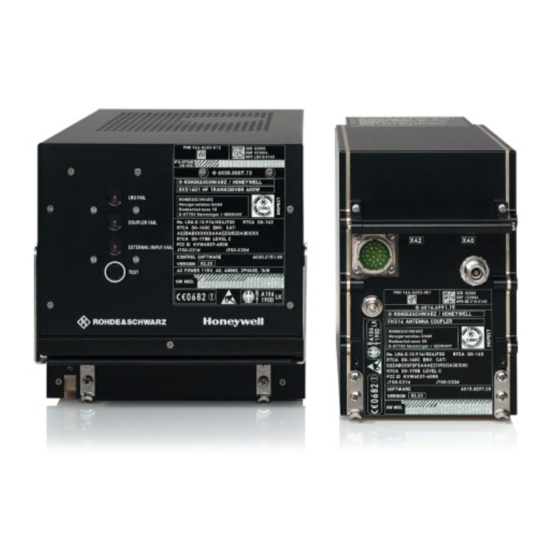
- Page 22 Honeywell COMPONENT MAINTENANCE MANUAL PART NUMBER 964-0452 Transceiver Front Panel and Rear Connector Figure 2 I.B.1516A Page 3 23-12-01 Mar 30/01...
- Page 23 The specifications for the XK516D1 HF Transceiver are listed in Fig. 4. D. Operation of XK516D1 in Voice Mode (1) To operate the XK516D1 in Voice Mode, the operator selects either SSB Mode or AM Mode on the Radio Control Panel and selects the frequency.
- Page 24 Honeywell COMPONENT MAINTENANCE MANUAL PART NUMBER 964-0452 Interconnect Diagram, HF Voice/Data Radio System Figure 3 I.B.1516A Page 5 23-12-01 Mar 30/01...
- Page 25 Honeywell COMPONENT MAINTENANCE MANUAL PART NUMBER 964-0452 Transceiver Specifications Figure 4 (Sheet 1) 1I.B.1516A Page 6 23-12-01 Mar 30/01...
- Page 26 Honeywell COMPONENT MAINTENANCE MANUAL PART NUMBER 964-0452 Transceiver Specifications Figure 4 (Sheet 2) I.B.1516A Page 7 23-12-01 Mar 30/01...
- Page 27 Honeywell COMPONENT MAINTENANCE MANUAL PART NUMBER 964-0452 Primary mode. Backup to 516/517 Interface. Tune power (MPSC) Transceiver Specifications Figure 4 (Sheet 3) 1I.B.1516A Page 8 23-12-01 Mar 30/01...
- Page 28 Honeywell COMPONENT MAINTENANCE MANUAL PART NUMBER 964-0452 Transceiver Specifications Figure 4 (Sheet 4) I.B.1516A Page 9 23-12-01 Mar 30/01...
- Page 29 Honeywell COMPONENT MAINTENANCE MANUAL PART NUMBER 964-0452 Transceiver Specifications Figure 4 (Sheet 5) 1I.B.1516A Page 10 23-12-01 Mar 30/01...
- Page 30 Honeywell COMPONENT MAINTENANCE MANUAL PART NUMBER 964-0452 Transceiver Specifications Figure 4 (Sheet 6) I.B.1516A Page 11 23-12-01 Mar 30/01...
- Page 31 Honeywell COMPONENT MAINTENANCE MANUAL PART NUMBER 964-0452 (4) The HFDR then tunes to the first frequency and listens for a periodic uplink (called a squitter) from the ground station. If no squitter is detected within 32 seconds, the HFDR tunes to the next frequency on its list.
- Page 32 Honeywell COMPONENT MAINTENANCE MANUAL PART NUMBER 964-0452 Block Diagram (Simplified), Transceiver Figure 5 When receiving, the RF signal is down-converted by means of 2 mixer stages to the second IF of 25kHz. This IF signal is digitized and undergoes further conditioning in the signal pro- cessor.
- Page 33 Honeywell COMPONENT MAINTENANCE MANUAL PART NUMBER 964-0452 built-in tests can be initiated, manually via a front panel test button, or from the aircraft main- tenance system, via an ARINC 429 interface. The results of the continuous monitoring are permanently supplied to the CFDS/CMC in the normal mode, according to ARINC 604.
- Page 34 Honeywell COMPONENT MAINTENANCE MANUAL PART NUMBER 964-0452 HFDR #2 IN HI HFDR#2 IN HI +15v TP-5J HFDR #2 IN LO HFDR#2 IN LO TP-5K -15v 115V SWITCHED A +28v HFDR #2 OUT HI HFDR#2 OUT HI BP-2 TP-5G HFDR #2 OUT LO...
- Page 35 Honeywell COMPONENT MAINTENANCE MANUAL PART NUMBER 964-0452 Functional Diagram, Receiver/Transmitter, A1 Figure 7 I.B.1516A Page 17/18 23-12-01 Mar 30/01...
- Page 36 Honeywell COMPONENT MAINTENANCE MANUAL PART NUMBER 964-0452 Block Diagram, Power Amplifier Board, A3 Figure 8 I.B.1516A Page 19/20 23-12-01 Mar 30/01...
- Page 37 Honeywell COMPONENT MAINTENANCE MANUAL PART NUMBER 964-0452 Along with the reference signal, the phase comparator of the PLL is also supplied with the down-converted frequency of VCO3. The mixing frequency for this down conversion is obtained from a second PLL. The reference frequency of the 2nd PLL is derived from a crystal oscillator (10Mhz), which is scaled down by a factor of 100.
- Page 38 Honeywell COMPONENT MAINTENANCE MANUAL PART NUMBER 964-0452 Amplifier Board, A31 The Amplifier Board amplifies the RF input from Receiver/Exciter, A1, with a level of –7dBm ± 3dB Peak Envelope Power (PEP) or Continuous Wave (CW) to a max- imum output power of 125W continuous wave (+51dBm) or 400W +0.5dB PEP (56dBm +0.5dB).
- Page 39 Honeywell COMPONENT MAINTENANCE MANUAL PART NUMBER 964-0452 (4) LED Board, A5 The LED Board, A5, contains the 3 LED indicators, which indicate: • LRU Fail • Coupler Fail • Control Fail The LED Board is connected to the Motherboard via a ribbon cable and connector, and also contains the switch for manual test initiation (X14).
- Page 40 (CCA), A2, and the HF Modem CCA, A10. When the Data Module components are installed into an XK516D1 HF Transceiver, they allow the radio to maintain all the func- tions of the Voice version Transceiver, but in addition, allows the Transceiver to operate in HF Data Link (HFDL) mode as specified by ARINC 753 and ARINC 635.
- Page 41 Honeywell COMPONENT MAINTENANCE MANUAL PART NUMBER 964-0452 Block Diagram, Synthesizer Loop 1 Figure 9 I.B.1516A Page 25/26 23-12-01 Mar 30/01...
- Page 42 Honeywell COMPONENT MAINTENANCE MANUAL PART NUMBER 964-0452 Block Diagram, Synthesizer Loop 2 and 3 Figure 10 I.B.1516A Page 27/28 23-12-01 Mar 30/01...
- Page 43 Honeywell COMPONENT MAINTENANCE MANUAL PART NUMBER 964-0452 output signal of 40MHz is brought to TTL level by transistors, V62 and V63, re- spectively, and supplied to 4:1 divider, D16, or 5:1 divider, D17. The 10MHz out- put frequency of the 4:1 divider is divided by 2 in D5-A, and then by 5. The 5MHz signat is required as a clock pulse for digital direct synthesis (DDS) in loop 3.
- Page 44 Honeywell COMPONENT MAINTENANCE MANUAL PART NUMBER 964-0452 FREQUENCY (MHZ) DATA WORD FROM 2000 2049.9 2050 2299.9 2300 2499.9 2500 2649.9 2650 2799.9 2800 2949.9 2950 3099.9 3100 3299.9 3300 3449.9 3500 3649.9 3650 3849.9 3850 4049.9 4050 4299.9 4300 4549.9 4550 4849.9...
- Page 45 Honeywell COMPONENT MAINTENANCE MANUAL PART NUMBER 964-0452 FREQUENCY (MHZ) DATA WORD FROM 9720 9949.9 9950 10199.9 10200 10449.9 10450 10749.9 10750 11099.9 11100 11449.9 11450 11849.9 11850 12299.9 12300 12799.9 12800 13249.9 13250 13469.9 13470 13729.9 13730 13999.9 14000 14299.9 14300 14599.9...
- Page 46 Honeywell COMPONENT MAINTENANCE MANUAL PART NUMBER 964-0452 FREQUENCY (MHZ) DATA WORD FROM 20400 20599.9 20600 20849.9 20850 21099.9 21100 21349.9 21350 21599.9 21600 21899.9 21900 22199.9 22200 22599.9 22600 22999.9 23000 23449.9 23450 23999.9 24000 24339.9 24340 24699.9 24700 24999.9 25000 25199.9...
- Page 47 Honeywell COMPONENT MAINTENANCE MANUAL PART NUMBER 964-0452 The Loop divider consists of D19, a predivider, whose division ratio can be var- ied between 11:1 and 10:1, and D6, a synthesizer module, containing an A di- vider, an N divider, a phase comparator, and an R divider.
- Page 48 Honeywell COMPONENT MAINTENANCE MANUAL PART NUMBER 964-0452 Add. MADR2 MADR1 MADR0 D15......DO –...
- Page 49 Honeywell COMPONENT MAINTENANCE MANUAL PART NUMBER 964-0452 Block Diagram, Receiver Analog Front-End Figure 14 I.B.1516A Page 35/36 23-12-01 Mar 30/01...
- Page 50 Honeywell COMPONENT MAINTENANCE MANUAL PART NUMBER 964-0452 Block Diagram, Transceiver AF/Digital Section Figure 15 I.B.1516A Page 37/38 23-12-01 Mar 30/01...
- Page 51 Honeywell COMPONENT MAINTENANCE MANUAL PART NUMBER 964-0452 Loop 3 The frequency for the 1st mixer (1. OSC), which can vary between 42025kHz and 70024.9kHz in increments of 100Hz, is generated in loop 3. The VCO of this loop is synchronized to the sum of the output frequency of loop 2 and the output frequency of the DDS.
- Page 52 Honeywell COMPONENT MAINTENANCE MANUAL PART NUMBER 964-0452 From the Front End to the 2nd Intermediate Frequency The input signal arrives at antenna jack X201 via a 9th-degree Cauer low-pass filter, which ensures the necessary signal-to-image ratio. The subsequent push-pull mixer, composed of transformer, T2, and 4-way switch, S40, is used for conversion to a 40.025MHz IF signal.
- Page 53 Honeywell COMPONENT MAINTENANCE MANUAL PART NUMBER 964-0452 IF Processor, A12 All settings of the IF processor are made via the bidirectional EXTERNAL DATA bus (16 bit, 3 addresses). The tristate modules, A12D15, D16, D17, and D18, permit access to the bus; addressing is effected by MS2.
- Page 54 Honeywell COMPONENT MAINTENANCE MANUAL PART NUMBER 964-0452 Synchronous demodulator, with which the frequency of the signal is converted in such a way that the carrier obtains a frequency of zero. A digital phase-locked loop (DPLL) ensures that the phase of the demodulated signal also remains constant within a channel width.
- Page 55 Honeywell COMPONENT MAINTENANCE MANUAL PART NUMBER 964-0452 Block Diagram, Exciter Analog Section Figure 16 I.B.1516A Page 43/44 23-12-01 Mar 30/01...
- Page 56 Honeywell COMPONENT MAINTENANCE MANUAL PART NUMBER 964-0452 BFO, which converts the input signal to the correct IF position. As in the receive section, it is a synchronous modulator that selects the lower or upper sideband (LSB/USB) as necessary. In this context, it must be borne in mind that the sub- sequent stages generate the reverse frequency position (Ref.
- Page 57 Honeywell COMPONENT MAINTENANCE MANUAL PART NUMBER 964-0452 Low-pass filter, L1, L2, L3, L4, suppresses the oscillator spurious output, which could reach the RF output via the final balanced attenuation of the mixer. The RF signal is rectified at the output (nominal value –7dBm) in diode detector, V1, V68, and V9, and compared to a threshoLd corresponding to an RF level of about –16dBm.
- Page 58 Honeywell COMPONENT MAINTENANCE MANUAL PART NUMBER 964-0452 Block Diagram, ADP, A2 Figure 17 I.B.1516A 23-12-01 Page 47/48 Mar 30/01...
- Page 59 Honeywell COMPONENT MAINTENANCE MANUAL PART NUMBER 964-0452 A2P1 SDU EMULATION EN SPARE DISC IN * OTHER SIDE MODE EN POS/CQ IN VHF EN HFDR INSTALLED TX INHIBIT STATUS TX INHIBIT POLARITY TX INHIBIT TX INHIBIT OVERRIDE BOOT WR ENABLE ATP ENABLE...
- Page 60 Honeywell COMPONENT MAINTENANCE MANUAL PART NUMBER 964-0452 A2P2 ADP PRESENT HFM RESET SDI0 SDI1 INT HFDR FAULT INTFC SPARE 1 * INTFC SPARE 2 * DATA KEY MON TUNE IN PROGRESS TUNE FAIL HFM TX ACTIVE HFM PRESENT HFM FAULT...
- Page 61 Honeywell COMPONENT MAINTENANCE MANUAL PART NUMBER 964-0452 Block Diagram, Amplifier Board, A31 Figure 19 I.B.1516A Page 51/52 23-12-01 Mar 30/01...
- Page 62 Honeywell COMPONENT MAINTENANCE MANUAL PART NUMBER 964-0452 The Core software provides additional power-up self-tests and the ADP Data Link functions. These functions include such things as searching and logging onto HF Data Link channels, processing uplink and downlink packets, and Data Module built-in-tests/fault reporting.
- Page 63 Honeywell COMPONENT MAINTENANCE MANUAL PART NUMBER 964-0452 protection for the gate of V4. The operating point of transistor, V4, is set to permit a drain current of ID = 100mA to flow. Amplified by about 16dB, the RF signal is supplied via the series resistor R50 to the voltage-controlled attenuator.
- Page 64 Honeywell COMPONENT MAINTENANCE MANUAL PART NUMBER 964-0452 The RF signal is forwarded via coupling capacitor, C74, to matching network C71, R127, and transformer, T5, or the input of the final stage. C225 is wired in parallel to the output of transistor, T5, for compensation purposes. The RF signal is supplied via coupling capacitors, C77 and C78, which are used for direct voltage isolation.
- Page 65 Introduction Amplifier Control, A33, performs 2 primary functions. First, it regulates the out- put power of the XK516D1 400W HF Transceiver, such that, operating under normal conditions, the output power is kept constant at the nominal value.In this connection, the Amplifier Control continuously receives information about the forward and reverse power from the directional coupler located in Harmonic Fil- ter, A32.
- Page 66 Honeywell COMPONENT MAINTENANCE MANUAL PART NUMBER 964-0452 Block Diagram, Amplifier Control, A33 Figure 20 I.B.1516A Page 57/58 23-12-01 Mar 30/01...
- Page 67 With data bit D13 set, the signal TEST400W = H, and shorts the actual value of average power control, N6-D, to ground via V38. This deselects the restriction of the average power value to 125W in the XK516D1 HF Transceiver, in order to obtain 400W for intermodulation measurement with 2 tones, for instance.
- Page 68 FORV, REVV, and ZERO signals. These now form an exact measurement of the forward and reverse power at the transceiver output. The output power of the XK516D1 HF Transceiver is regulated by Amplifier Control, A33, in such a way that a forward power of 400W...
- Page 69 Honeywell COMPONENT MAINTENANCE MANUAL PART NUMBER 964-0452 The actual value can be shorted to ground at N5.3 with V38, thus deselecting the average power control. For VSWR control, the weighted sum of the FORWARD and REVERSE signals is compared with reference voltage, VREF, by means of operational amplifier, N3-A.
- Page 70 Honeywell COMPONENT MAINTENANCE MANUAL PART NUMBER 964-0452 ALC Amplifier The DIODES signal reaches the first phase-boosting section, provided by N4-C, via operational amplifier, N4-D, which is connected with v = 1 as a noninverting amplifier. The amplification from R15 and R104 results in v = –2 for direct volt- age.
- Page 71 Honeywell COMPONENT MAINTENANCE MANUAL PART NUMBER 964-0452 Monitoring, CM, BIT Power Amplifier, A3, is able to detect and locate accurately mismatching and overtemperature as well as module defects with the aid of monitoring circuits on Amplifier Control, A33. The TSFS signal comes from Amplifier Board, A31, and is a measure of the heat sink temperature at the final stage transistors.
- Page 72 Honeywell COMPONENT MAINTENANCE MANUAL PART NUMBER 964-0452 Gates, D9-B and D9-C, link the SENS2 and U2.2 signals in such a way that BI- TAMP = H, and therefore, a fault is reported in Amplifier Board, A31, if the ALC vottage is in the normal range below 5V, but the HF voltage present at the output of Amplifier Board, A31, is still too LOW (SENS2 = HI).
- Page 73 Honeywell COMPONENT MAINTENANCE MANUAL PART NUMBER 964-0452 Block Diagram, Harmonic Filter, A32 Figure 21 I.B.1516A Page 65/66 23-12-01 Mar 30/01...
- Page 74 Honeywell COMPONENT MAINTENANCE MANUAL PART NUMBER 964-0452 Transmit/Receive relay Transmit/receive relay, K1, connects the receive signal from the antenna to the receiver and switches the RF-power from the amplifier to the antenna. BITREL circuit-breaker The BITREL signal actuates a relay, which switches to 47B during test opera- tion.
- Page 75 Honeywell COMPONENT MAINTENANCE MANUAL PART NUMBER 964-0452 states in the power supply. In addition, the Regulator Board, A41, forms the in- terface between Power Supply, A4, and Controller Voice, A8, via the bidirection- al module data bus. Ref. Fig. 22 for block diagram.
- Page 76 Honeywell COMPONENT MAINTENANCE MANUAL PART NUMBER 964-0452 Block Diagram, Regulator Board, A41 Figure 22 I.B.1516A Page 69/70 23-12-01 Mar 30/01...
- Page 77 Honeywell COMPONENT MAINTENANCE MANUAL PART NUMBER 964-0452 filter capacitor, C21. As a result, the output voltage can still be maintained at +6V at C20 with full output current. R66 provides the output of N1 with a base load, and thus prevents oscillation of the voltage regulator, as does correction capacitor, C39.
- Page 78 Honeywell COMPONENT MAINTENANCE MANUAL PART NUMBER 964-0452 sues a fault message to Controller Voice, A8 via D2-A and D1A only after about 15ms. This delay is necessary in order to prevent the drop in the +28V supply voltage in the event of a power failure during the 10ms transparency period be- ing incorrectly interpreted as a power supply fault.
- Page 79 Honeywell COMPONENT MAINTENANCE MANUAL PART NUMBER 964-0452 The SENSE signal is formed in order to detect power system failures of 1 or more phases with diodes, V24, V25, and V32. In normal circumstances, the volt- age never falls below 10V at this point. A direct voltage of +6.8V, limited by Ze- ner diode, V54, is present at the gate of V57, whereby the source connection lies at about +4V.
- Page 80 (6) EMC Filter, A7 The EMC filter is composed of a rear panel and the Filter Board, A71, which connects the external cabling with the basic assemblies of the XK516D1 400W HF Transceiver. Refer to Fig. 23 for block diagram.
- Page 81 Honeywell COMPONENT MAINTENANCE MANUAL PART NUMBER 964-0452 Block Diagram, Filter Board, A71 Figure 23 (7) Controller D, A8, and Interface D, A9 Controller D, A8 The functional units located on the Controller Assembly are described here. Ref. Fig. 24 for block diagram.
- Page 82 Honeywell COMPONENT MAINTENANCE MANUAL PART NUMBER 964-0452 purposes, the crystal oscillator can be isolated from the processor by jumper, X2. Functional units that are integrated in the processor are: a Timers The processor has 3 independent timers, which timers receive their clock pulse from the processor clock.
- Page 83 Honeywell COMPONENT MAINTENANCE MANUAL PART NUMBER 964-0452 Block Diagram, Controller D, A8 Figure 24 I.B.1516A Page 77/78 23-12-01 Mar 30/01...
- Page 84 Honeywell COMPONENT MAINTENANCE MANUAL PART NUMBER 964-0452 SIGNAL NAME WRITE READ —— EPROM MCS0 EEPROM EEPROM USART Test Interface USART Test Interface MCS2 USART Coupler USART Coupler MCS3 —— —— PCS5 Module Bus Data Module Bus Data PCS6 Module Bus Control Fault LEDs Parallel Input PCS0 ——...
- Page 85 Honeywell COMPONENT MAINTENANCE MANUAL PART NUMBER 964-0452 Connection of an ASCII Terminal Figure 26 USART Modules, D20 and D12, convert the parallel data on the data bus into a serial data flow, and serial incoming data are transformed into a parallel data word.
- Page 86 Honeywell COMPONENT MAINTENANCE MANUAL PART NUMBER 964-0452 to the control unit. If a fault state changes in an HF assembly, a LOW pulse is initiated on the MINT line via an open-collector transistor. Now the control unit can read the fault state via the module bus. A module select is available for each HF assembly (MS1-MS4).
- Page 87 Honeywell COMPONENT MAINTENANCE MANUAL PART NUMBER 964-0452 A minimum interval of 4 bits is defined between 2 ARINC words. Minimum Interval between two ARINC Words Figure 28 The bit rate is 12.5kbit/s. A TTL high pulse is obtained separately for a logical 0 and a logical 1 from the inverted and noninverted lines via 2 comparators at each ARINC input circuit.
- Page 88 Honeywell COMPONENT MAINTENANCE MANUAL PART NUMBER 964-0452 Block Diagram, ARINC Input Figure 31 A pause of at least 3 bits between the OR clock pulse is detected by the pause recognition circuit. The 32-bit ARINC word is reloaded from the shift register in a 32-bit holding register with the positive edge of the circuit, and an interrupt flip-flop is set.
- Page 89 Honeywell COMPONENT MAINTENANCE MANUAL PART NUMBER 964-0452 Block Diagram, ARINC Output Figure 33 Parallel output Open-collector transistor, V4, is controlled via a port output on module, D3. This generates the KEYEV signal. Parallel input The Logic states of discrete input lines can be inquired by input port modules, D1 and D2.
- Page 90 Honeywell COMPONENT MAINTENANCE MANUAL PART NUMBER 964-0452 Block Diagram, Interface D, A9 Figure 34 Page 85 I.B.1516A Page 57 23-12-01 Mar 30/01...
- Page 91 Honeywell COMPONENT MAINTENANCE MANUAL PART NUMBER 964-0452 (8) HF Modem, A10 HF Modem, A10, performs the necessary functions to implement both transmission and reception of the audio waveform specified in ARINC 635. Digital message packets re- ceived from the ADP, A2, are encoded, interleaved and scrambled to generate a stream of binary 1’s and 0’s, all used to modulate the phase of a 1440Hz carrier.
- Page 92 Honeywell COMPONENT MAINTENANCE MANUAL PART NUMBER 964-0452 Block Diagram, HF Modem, A10 Figure 35 I.B.1516A Page 87/88 23-12-01 Mar 30/01...
- Page 93 Honeywell COMPONENT MAINTENANCE MANUAL PART NUMBER 964-0452 A2P1 +15V +15V +15V –15V –15V –15V RX-DATA-AF TX-DATA-AF IN-DATA-KEY DATA-KEY-MON RESET OUT HFM-RESET DATA-ENABLE ADP-SPARE-1 ADP-SPARE-2 DM-TEST CONFIG3 * CONFIG4 * CONFIG5 * CONFIG6 * CONFIG7 * HFM-PRESENT HFM-FAULT HFM-RX-ACTIVE HFM-TX-ACTIVE STAT4 *...
- Page 94 Honeywell COMPONENT MAINTENANCE MANUAL PART NUMBER 964-0452 (9) ON OFF Module, A15 The ON OFF Module, A15, contains 3 relays for switching ON and OFF the transceiver. The relay contacts are closed when the line ONREL is connected to ground. Transform-...
- Page 95 Honeywell COMPONENT MAINTENANCE MANUAL PART NUMBER 964-0452 TESTING AND FAULT ISOLATION Introduction This section contains information and instructions for testing and of the Transceiver. The proce- dures and data are intended to assist in testing, isolation of faults to a module, and elimination of faults by replacement of the modules.
- Page 96 Honeywell COMPONENT MAINTENANCE MANUAL PART NUMBER 964-0452 (3) Install the GSE Setup software diskette, Part No. 998-2403-50X, into drive A of the PC (if A is not the current drive, substitute the proper drive). (4) From the Program Manager, select File, Run.
- Page 97 Honeywell COMPONENT MAINTENANCE MANUAL PART NUMBER 964-0452 D. Power Connection Integrity Check Use an ohmmeter to check that the following Transceiver rear connector power pins are not shorted to Ground: BP-2 BP-5 BP-3 BP-6 BP-4 BP-7 HF Transceiver ATP All relevant receiver and transmitter data are checked in the tests. The ATP is performed if no adequate BITE fault message is present, or after repair of faults, to verify operation before instal- lation of the Transceiver on an aircraft.
- Page 98 Honeywell COMPONENT MAINTENANCE MANUAL PART NUMBER 964-0452 Refer to Fig. 117A for a sample test report. NOTE: The extension automatically increments the next time a report is printed to file; for instance, the second time changes the extension to L01, etc.
- Page 99 Honeywell COMPONENT MAINTENANCE MANUAL PART NUMBER 964-0452 Test Setup Figure 101 (Sheet 1) 23-12-01 I.B.1516A Page 105/106 Oct 25/02...
- Page 100 Honeywell COMPONENT MAINTENANCE MANUAL PART NUMBER 964-0452 Test Setup Figure 101 (Sheet 2) 23-12-01 I.B.1516A Page 107/108 Oct 25/02...
- Page 101 Honeywell COMPONENT MAINTENANCE MANUAL PART NUMBER 964-0452 Test Setup Figure 101 (Sheet 3) 23-12-01 I.B.1516A Page 109/110 Oct 25/02...
- Page 102 Honeywell COMPONENT MAINTENANCE MANUAL PART NUMBER 964-0452 Test Setup Figure 101 (Sheet 4) 23-12-01 I.B.1516A Page 111/112 Oct 25/02...
- Page 103 Honeywell COMPONENT MAINTENANCE MANUAL PART NUMBER 964-0452 Test Setup Figure 101 (Sheet 5) 23-12-01 I.B.1516A Page 113/114 Oct 25/02...
- Page 104 Honeywell COMPONENT MAINTENANCE MANUAL PART NUMBER 964-0452 9. Fault Isolation A. General This section contains information and instructions for fault isolation of the HF Transceiver. The information is intended to aid in isolating and eliminating faults to the Module level.
- Page 105 Honeywell COMPONENT MAINTENANCE MANUAL PART NUMBER 964-0452 (3) Top Level Assembly Illustrated Parts List (IPL) The locations of individual modules are indicated in the Top Level Assembly IPL. (4) Test Points (TP) Various internal voltages and signals are tied to the rear connector of the Transceiver, and can be accessed and measured in the test panel setup.
- Page 106 Honeywell COMPONENT MAINTENANCE MANUAL PART NUMBER 964-0452 occurs, the faults are displayed on several pages. The number of available pages and the current page number are displayed in the top right field; i.e., "2/3" means page 2 of 3 pages.
- Page 107 Honeywell COMPONENT MAINTENANCE MANUAL PART NUMBER 964-0452 Transceiver LRU Identification Menu (ABD0048) Figure 103 Transceiver Last Leg Report with No Fault Indicated (ABD0048) Figure 104 23-12-01 I.B.1516A Page 118 Oct 25/02...
- Page 108 Honeywell COMPONENT MAINTENANCE MANUAL PART NUMBER 964-0452 Transceiver Last Leg Report with Failures Detected (ABD0048) Figure 105 Previous Leg Report with Failure Detected (ABD0048) Figure 106 23-12-01 I.B.1516A Page 119 Oct 25/02...
- Page 109 Honeywell COMPONENT MAINTENANCE MANUAL PART NUMBER 964-0452 Transceiver Ground Report with No Fault Detected (ABD0048) Figure 107 23-12-01 I.B.1516A Page 120 Oct 25/02...
- Page 110 Honeywell COMPONENT MAINTENANCE MANUAL PART NUMBER 964-0452 Transceiver Ground Report with failure detected (ABD0048) Figure 108 23-12-01 I.B.1516A Page 121 Oct 25/02...
- Page 111 Honeywell COMPONENT MAINTENANCE MANUAL PART NUMBER 964-0452 Transceiver Trouble Shooting Data Menu with no fault detected (ABD0048) Figure 109 Transceiver Trouble Shooting Data Menu with Failure Detected (ABD0048) Figure 110 23-12-01 I.B.1516A Page 122 Oct 25/02...
- Page 112 Honeywell COMPONENT MAINTENANCE MANUAL PART NUMBER 964-0452 Transceiver Ground Scanning Menu with no fault detected (ABD0048) Figure 111 23-12-01 I.B.1516A Page 122.1 Oct 25/02...
- Page 113 Honeywell COMPONENT MAINTENANCE MANUAL PART NUMBER 964-0452 Transceiver Ground Scanning Menu with failure detected (ABD0048) Figure 112 23-12-01 I.B.1516A Page 122.2 Oct 25/02...
- Page 114 Honeywell COMPONENT MAINTENANCE MANUAL PART NUMBER 964-0452 FAILURE IN LAST LEG/PREVIOUS FAILURE LEG REPORT TROUBLE SHOOT CLASS Loss of Synthesizer Lock RX/TX Amplifier output too low AMPL Amplifier temperature too high AMPL TEMP Supply voltage Amplifier (50V) out of range...
- Page 115 Honeywell COMPONENT MAINTENANCE MANUAL PART NUMBER 964-0452 FAILURE TROUBLE SHOOT FAILURE DESCRIPTION MESSAGE MESSAGE CLASS Loss of Synthesizer Lock RX/TX (100) Amplifier temperature too high AMPL (0010) Supply voltage Amplifier (50V) out of range PWR SPLY (0010) Voltage (28V) out of range...
- Page 116 Honeywell COMPONENT MAINTENANCE MANUAL PART NUMBER 964-0452 Transceiver Test Menu with No Fault Detected (ABD0048) Figure 115 Transceiver Test Menu with Failure Detected (ABD0048) Figure 116 F . Basic Voltage Test Procedure This test procedure (Fig. 117) is performed in conjunction with faults with which a BITE eval- uation is not possible, or the unit will not power up.
- Page 117 Honeywell COMPONENT MAINTENANCE MANUAL PART NUMBER 964-0452 ment voltages are checked and branched to the fault isolation procedures for the Power Sup- ply and/or Controller D and Interface D modules. STEP PROCEDURE RESULTS COMMENTS INITIAL CONDITIONS Connect Transceiver per test setup procedure (Fig. 101).
- Page 118 Honeywell COMPONENT MAINTENANCE MANUAL PART NUMBER 964-0452 Depending upon the fault, the fault isolation chart indicates the module suspected of having a fault. In the event of no fault being reported by the BITE system, e.g., in the case of unspecified fault reports, the chart advances to the Transceiver ATP.
- Page 119 Honeywell COMPONENT MAINTENANCE MANUAL PART NUMBER 964-0452 ATP SW Configuration Check Pass System SW Configuration Check Pass Part Number..: 964-0452-012 Serial Number..: 1230 Start time...: 06/26/2002 11:29:44 Output Log Filename..: c:\ATEASY\HFDR\1230.log ------------------------ PERFORMING ATP ----------------------- See end of log for details --------------------------------------------------------------- UUT Type.....: HFDR Transceiver...
- Page 120 Honeywell COMPONENT MAINTENANCE MANUAL PART NUMBER 964-0452 ---------------------------------------------------------------------------- Task4 : Transmit Voice Mode Test-Name Status --- ------------------------------ ---------------------------------- ------ 001 Transmit Operation PASS 002 Narrow Band 2.000 MHz PASS 003 Narrow Band 2.799 MHz PASS 004 Narrow Band 24.000 MHz PASS 005 Narrow Band 29.999 MHz...
- Page 121 Honeywell COMPONENT MAINTENANCE MANUAL PART NUMBER 964-0452 Task9 : Spurious Emissions Ext Data Test-Name Status --- ------------------------------ ---------------------------------- ------ 001 Ext Data 29.0000 MHz PASS 002 Ext Data 20.0000 MHz PASS 003 Ext Data 10.0000 MHz PASS 004 Ext Data 2.0000 MHz...
- Page 122 Honeywell COMPONENT MAINTENANCE MANUAL PART NUMBER 964-0452 003 AM 20.1000 MHz PASS 004 AM 29.1000 MHz PASS ---------------------------------------------------------------------------- Task15 : SELCAL Test-Name Status --- ------------------------------ ---------------------------------- ------ 001 10 MHz 100uV 30% PASS 002 10 MHz 1000uV 30% PASS 003 10 MHz 1000uV 80%...
- Page 123 Honeywell COMPONENT MAINTENANCE MANUAL PART NUMBER 964-0452 D5 55 55 55 2A AA AA AA 55 55 55 D5 005 ICAO ID #2 PASS D5 55 55 55 2A AA AA AA 55 55 55 D5 006 Position In PASS...
- Page 124 Honeywell COMPONENT MAINTENANCE MANUAL PART NUMBER 964-0452 -------------------------- ----- -------- ---------- -------- ------ TP-5B Air/Gnd Polarity Lo 0.0 pass TP-5B Air/Gnd Polarity Hi 1.0 pass MP-4G Air/Gnd Lo 0.0 pass MP-4G Air/Gnd Hi 1.0 pass TP-3G Tx Inhibit Lo 0.0 pass TP-3G Tx Inhibit Hi 1.0 pass...
- Page 125 Honeywell COMPONENT MAINTENANCE MANUAL PART NUMBER 964-0452 ICAO ID18 Lo 0.0 pass ICAO ID19 Hi 1.0 pass ICAO ID19 Lo 0.0 pass ICAO ID20 Hi 1.0 pass ICAO ID20 Lo 0.0 pass ICAO ID21 Hi 1.0 pass ICAO ID21 Lo 0.0 pass...
- Page 126 Honeywell COMPONENT MAINTENANCE MANUAL PART NUMBER 964-0452 ---------------------------------------------------------------------------- Task21 : CSI Coupler Test-Name Status --- ------------------------------ ---------------------------------- ------ 001 Interface Detection PASS FK516 115V Found 002 Tuning Sequence in CSI Mode PASS 003 Transmission in CSI Mode PASS 004 Interlock Function...
- Page 127 Honeywell COMPONENT MAINTENANCE MANUAL PART NUMBER 964-0452 010 SSB 14.4900 MHz PASS VSWR 1.08 B0 C*00C3 D1 E0 L*0250 N*00 R0 E14.491 N002/001 011 SSB 19.5100 MHz PASS VSWR 1.15 B0 C*00CB D0 E0 L*002A N*0B R0 E19.512 N002/001 012 SSB 22.9900 MHz PASS VSWR 1.13 B0 C*0184 D0 E0 L*0012 N*04 R0 E22.992 N002/001...
- Page 128 Honeywell COMPONENT MAINTENANCE MANUAL PART NUMBER 964-0452 UUT....: HFDR Transceiver Part Number..: 964-0452-012 Serial Number..: 1230 Start time...: 06/26/2002 11:29:44 Stop time....: 06/26/2002 12:28:11 Output Log Filename..: c:\ATEASY\HFDR\1230.log Profile....: 1. -012 ************************************ ATP PASSED ************************************ ************************************ TEST PASS ************************************ 106 Tests Analyzed Operator..: Fausto M...
- Page 129 Honeywell COMPONENT MAINTENANCE MANUAL PART NUMBER 964-0452 Transceiver Fault Isolation Procedure Figure 118 (Sheet 1) 23-12-01 I.B.1516A Page 122.19/122.20 Oct 25/02...
- Page 130 Honeywell COMPONENT MAINTENANCE MANUAL PART NUMBER 964-0452 Transceiver Fault Isolation Procedure Figure 118 (Sheet 2) 23-12-01 I.B.1516A Page 123/124 Oct 25/02...
- Page 131 Honeywell COMPONENT MAINTENANCE MANUAL PART NUMBER 964-0452 Transceiver Fault Isolation Procedure Figure 118 (Sheet 3) 23-12-01 I.B.1516A Page 125/126 Oct 25/02...
- Page 132 Honeywell COMPONENT MAINTENANCE MANUAL PART NUMBER 964-0452 Transceiver Fault Isolation Procedure Figure 118 (Sheet 3) 23-12-01 I.B.1516A Page 125/126 Oct 25/02...
- Page 133 Honeywell COMPONENT MAINTENANCE MANUAL PART NUMBER 964-0452 Transceiver Fault Isolation Procedure Figure 118 (Sheet 4) 23-12-01 I.B.1516A Page 127/128 Oct 25/02...
- Page 134 Honeywell COMPONENT MAINTENANCE MANUAL PART NUMBER 964-0452 Transceiver Fault Isolation Procedure Figure 118 (Sheet 5) I.B.1516A 23-12-01 Page 129/130 Oct 25/02...
- Page 135 Honeywell COMPONENT MAINTENANCE MANUAL PART NUMBER 964-0452 Transceiver Fault Isolation Procedure Figure 118 (Sheet 6) 23-12-01 I.B.1516A Page 131/132 Oct 25/02...
- Page 136 Honeywell COMPONENT MAINTENANCE MANUAL PART NUMBER 964-0452 Transceiver Fault Isolation Procedure Figure 118 (Sheet 7) 23-12-01 I.B.1516A Page 133/134 Oct 25/02...
- Page 137 Honeywell COMPONENT MAINTENANCE MANUAL PART NUMBER 964-0452 Transceiver Fault Isolation Procedure Figure 118 (Sheet 8) 23-12-01 I.B.1516A Page 135/136 Oct 25/02...
- Page 138 Honeywell COMPONENT MAINTENANCE MANUAL PART NUMBER 964-0452 Transceiver Fault Isolation Procedure Figure 118 (Sheet 9) 23-12-01 I.B.1516A Page 137/138 Oct 25/02...
- Page 139 Honeywell COMPONENT MAINTENANCE MANUAL PART NUMBER 964-0452 REVISION SERIAL NUMBER REVISION DESCRIPTION NUMBER EFFECTIVITY Schematic, XK516D1 400W HF Transceiver Figure 119 (Sheet 1) I.B.1516A Page 139/140 23-12-01 Mar 30/01...
- Page 140 Honeywell COMPONENT MAINTENANCE MANUAL PART NUMBER 964-0452 Schematic, XK516D1 400W HF Transceiver Figure 119 (Sheet 2) I.B.1516A Page 141/142 23-12-01 Mar 30/01...
- Page 141 Honeywell COMPONENT MAINTENANCE MANUAL PART NUMBER 964-0452 REVISION SERIAL NUMBER REVISION DESCRIPTION NUMBER EFFECTIVITY Schematic, Receiver/Exciter Figure 120 (Sheet 1) I.B.1516A Page 143/144 23-12-01 Mar 30/01...
- Page 142 Honeywell COMPONENT MAINTENANCE MANUAL PART NUMBER 964-0452 Schematic, Receiver/Exciter, A1 Figure 120 (Sheet 2) I.B.1516A Page 145/146 23-12-01 Mar 30/01...
- Page 143 Honeywell COMPONENT MAINTENANCE MANUAL PART NUMBER 964-0452 REVISION SERIAL NUMBER REVISION DESCRIPTION NUMBER EFFECTIVITY Schematic, RF Board Figure 121 (Sheet 1) I.B.1516A Page 147/148 23-12-01 Mar 30/01...
- Page 144 Honeywell COMPONENT MAINTENANCE MANUAL PART NUMBER 964-0452 Schematic, RF Board, A11 Figure 121 (Sheet 2) 23-12-01 Page 149/150 I.B.1516A Mar 30/01...
- Page 145 Honeywell COMPONENT MAINTENANCE MANUAL PART NUMBER 964-0452 Schematic, RF Board, A11 Figure 121 (Sheet 3) 23-12-01 Page 151/152 I.B.1516A Mar 30/01...
- Page 146 Honeywell COMPONENT MAINTENANCE MANUAL PART NUMBER 964-0452 Schematic, RF Board, A11 Figure 121 (Sheet 4) 23-12-01 I.B.1516A Page 153/154 Mar 30/01...
- Page 147 Honeywell COMPONENT MAINTENANCE MANUAL PART NUMBER 964-0452 Schematic, RF Board, A11 Figure 121 (Sheet 5) 23-12-01 Page 155/156 I.B.1516A Mar 30/01...
- Page 148 Honeywell COMPONENT MAINTENANCE MANUAL PART NUMBER 964-0452 Schematic, RF Board, A11 Figure 121 (Sheet 6) 23-12-01 Page 157/158 I.B.1516A Mar 30/01...
- Page 149 Honeywell COMPONENT MAINTENANCE MANUAL PART NUMBER 964-0452 Schematic, RF Board, A11 Figure 121 (Sheet 7) 23-12-01 Page 159/160 I.B.1516A Mar 30/01...
- Page 150 Honeywell COMPONENT MAINTENANCE MANUAL PART NUMBER 964-0452 Schematic, RF Board, A11 Figure 121 (Sheet 8) 23-12-01 I.B.1516A Page 161/162 Mar 30/01...
- Page 151 Honeywell COMPONENT MAINTENANCE MANUAL PART NUMBER 964-0452 Schematic, RF Board, A11 Figure 121 (Sheet 9) 23-12-01 I.B.1516A Page 163/164 Mar 30/01...
- Page 152 Honeywell COMPONENT MAINTENANCE MANUAL PART NUMBER 964-0452 Schematic, RF Board, A11 Figure 121 (Sheet 10) 23-12-01 Page 165/166 I.B.1516A Mar 30/01...
- Page 153 Honeywell COMPONENT MAINTENANCE MANUAL PART NUMBER 964-0452 Schematic, RF Board, A11 Figure 121 (Sheet 11) 23-12-01 I.B.1516A Page 167/168 Mar 30/01...
- Page 154 Honeywell COMPONENT MAINTENANCE MANUAL PART NUMBER 964-0452 Schematic, RF Board, A11 Figure 121 (Sheet 12) 23-12-01 I.B.1516A Page 169/170 Mar 30/01...
- Page 155 Honeywell COMPONENT MAINTENANCE MANUAL PART NUMBER 964-0452 Schematic, RF Board, A11 Figure 121 (Sheet 13) 23-12-01 I.B.1516A Page 171/172 Mar 30/01...
- Page 156 Honeywell COMPONENT MAINTENANCE MANUAL PART NUMBER 964-0452 Schematic, RF Board, A11 Figure 121 (Sheet 14) 23-12-01 I.B.1516A Page 173/174 Mar 30/01...
- Page 157 Honeywell COMPONENT MAINTENANCE MANUAL PART NUMBER 964-0452 Schematic, RF Board, A11 Figure 121 (Sheet 15) 23-12-01 Page 175/176 I.B.1516A Mar 30/01...
- Page 158 Honeywell COMPONENT MAINTENANCE MANUAL PART NUMBER 964-0452 Schematic, RF Board, A11 Figure 121 (Sheet 16) 23-12-01 I.B.1516A Page 177/178 Mar 30/01...
- Page 159 Honeywell COMPONENT MAINTENANCE MANUAL PART NUMBER 964-0452 Schematic, RF Board, A11 Figure 121 (Sheet 17) 23-12-01 Page 179/180 I.B.1516A Mar 30/01...
- Page 160 Honeywell COMPONENT MAINTENANCE MANUAL PART NUMBER 964-0452 REVISION SERIAL NUMBER REVISION DESCRIPTION NUMBER EFFECTIVITY Schematic, IF Processor Figure 122 (Sheet 1) I.B.1516A Page 181/182 23-12-01 Mar 30/01...
- Page 161 Honeywell COMPONENT MAINTENANCE MANUAL PART NUMBER 964-0452 Schematic, IF Processor, A12 Figure 122 (Sheet 2) I.B.1516A Page 183/184 23-12-01 Mar 30/01...
- Page 162 Honeywell COMPONENT MAINTENANCE MANUAL PART NUMBER 964-0452 Schematic, IF Processor, A12 Figure 122 (Sheet 3) I.B.1516A Page 185/186 23-12-01 Mar 30/01...
- Page 163 Honeywell COMPONENT MAINTENANCE MANUAL PART NUMBER 964-0452 Schematic, IF Processor, A12 Figure 122 (Sheet 4) I.B.1516A Page 187/188 23-12-01 Mar 30/01...
- Page 164 Honeywell COMPONENT MAINTENANCE MANUAL PART NUMBER 964-0452 Schematic, IF Processor, A12 Figure 122 (Sheet 5) I.B.1516A Page 189/190 23-12-01 Mar 30/01...
- Page 165 Honeywell COMPONENT MAINTENANCE MANUAL PART NUMBER 964-0452 REVISION SERIAL NUMBER REVISION DESCRIPTION NUMBER EFFECTIVITY Schematic, Subsynthesizer Figure 123 (Sheet 1) I.B.1516A Page 191/192 23-12-01 Mar 30/01...
- Page 166 Honeywell COMPONENT MAINTENANCE MANUAL PART NUMBER 964-0452 Schematic, Subsynthesizer, A13 Figure 123 (Sheet 2) I.B.1516A Page 193/194 23-12-01 Mar 30/01...
- Page 167 Honeywell COMPONENT MAINTENANCE MANUAL PART NUMBER 964-0452 Schematic, Subsynthesizer, A13 Figure 123 (Sheet 3) I.B.1516A Page 195/196 23-12-01 Mar 30/01...
- Page 168 Honeywell COMPONENT MAINTENANCE MANUAL PART NUMBER 964-0452 REVISION SERIAL NUMBER REVISION DESCRIPTION NUMBER EFFECTIVITY Schematic, On Off Board Figure 124 (Sheet 1) Page 197 I.B.1516A 23-12-01 Mar 30/01...
- Page 169 Honeywell COMPONENT MAINTENANCE MANUAL PART NUMBER 964-0452 Schematic, On Off Board Figure 124 (Sheet 2) Page 198 I.B.1516A 23-12-01 Mar 30/01...
- Page 170 Honeywell COMPONENT MAINTENANCE MANUAL PART NUMBER 964-0452 REVISION SERIAL NUMBER REVISION DESCRIPTION NUMBER EFFECTIVITY Schematic, Airborne Datalink Processor, A2 Figure 125 (Sheet 1) I.B.1516A Page 198.1/198.2 23-12-01 Mar 30/01...
- Page 171 Honeywell COMPONENT MAINTENANCE MANUAL PART NUMBER 964-0452 Schematic, Airborne Datalink Processor, A2 Figure 125 (Sheet 2) I.B.1516A Page 198.3/198.4 23-12-01 Mar 30/01...
- Page 172 Honeywell COMPONENT MAINTENANCE MANUAL PART NUMBER 964-0452 Schematic, Airborne Datalink Processor, A2 Figure 125 (Sheet 3) I.B.1516A Page 198.5/198.6 23-12-01 Mar 30/01...
- Page 173 Honeywell COMPONENT MAINTENANCE MANUAL PART NUMBER 964-0452 Schematic, Airborne Datalink Processor, A2 Figure 125 (Sheet 4) I.B.1516A Page 198.7/198.8 23-12-01 Mar 30/01...
- Page 174 Honeywell COMPONENT MAINTENANCE MANUAL PART NUMBER 964-0452 Schematic, Airborne Datalink Processor, A2 Figure 125 (Sheet 5) I.B.1516A Page 198.9/198.10 23-12-01 Mar 30/01...
- Page 175 Honeywell COMPONENT MAINTENANCE MANUAL PART NUMBER 964-0452 Schematic, Airborne Datalink Processor, A2 Figure 125 (Sheet 6) I.B.1516A Page 198.11/198.12 23-12-01 Mar 30/01...
- Page 176 Honeywell COMPONENT MAINTENANCE MANUAL PART NUMBER 964-0452 Schematic, Airborne Datalink Processor, A2 Figure 125 (Sheet 7) I.B.1516A Page 198.13/198.14 23-12-01 Mar 30/01...
- Page 177 Honeywell COMPONENT MAINTENANCE MANUAL PART NUMBER 964-0452 Schematic, Airborne Datalink Processor, A2 Figure 125 (Sheet 8) I.B.1516A Page 198.15/198.16 23-12-01 Mar 30/01...
- Page 178 Honeywell COMPONENT MAINTENANCE MANUAL PART NUMBER 964-0452 Schematic, Airborne Datalink Processor, A2 Figure 125 (Sheet 9) I.B.1516A Page 198.17/198.18 23-12-01 Mar 30/01...
- Page 179 Honeywell COMPONENT MAINTENANCE MANUAL PART NUMBER 964-0452 Schematic, Airborne Datalink Processor, A2 Figure 125 (Sheet 10) I.B.1516A Page 198.19/198.20 23-12-01 Mar 30/01...
- Page 180 Honeywell COMPONENT MAINTENANCE MANUAL PART NUMBER 964-0452 REVISION SERIAL NUMBER REVISION DESCRIPTION NUMBER EFFECTIVITY Schematic, HF Modem, A10 Figure 126 (Sheet 1) I.B.1516A Page 198.21/198.22 23-12-01 Mar 30/01...
- Page 181 Honeywell COMPONENT MAINTENANCE MANUAL PART NUMBER 964-0452 NOTES (UNLESS OTHERWISE SPECIFIED): 1. ALL CAPACITANCE VALUES ARE IN MICROFARADS. ALL CAPACITORS ARE 50V, 10%. 2. ALL RESISTANCE VALUES ARE IN OHMS. ALL RESISTORS ARE 1/8W, 1%. 3. GROUND SYMBOLS: = DIGITAL GROUND = ANALOG GND.
- Page 182 Honeywell COMPONENT MAINTENANCE MANUAL PART NUMBER 964-0452 Schematic, HF Modem, A10 Figure 126 (Sheet 3) I.B.1516A Page 198.25/198.26 23-12-01 Mar 30/01...
- Page 183 Honeywell COMPONENT MAINTENANCE MANUAL PART NUMBER 964-0452 Schematic, HF Modem, A10 Figure 126 (Sheet 4) I.B.1516A Page 198.27/198.28 23-12-01 Mar 30/01...
- Page 184 Honeywell COMPONENT MAINTENANCE MANUAL PART NUMBER 964-0452 Schematic, HF Modem, A10 Figure 126 (Sheet 5) I.B.1516A Page 198.29/198.30 23-12-01 Mar 30/01...
- Page 185 Honeywell COMPONENT MAINTENANCE MANUAL PART NUMBER 964-0452 Schematic, HF Modem, A10 Figure 126 (Sheet 6) I.B.1516A Page 198.31/198.32 23-12-01 Mar 30/01...
- Page 186 Honeywell COMPONENT MAINTENANCE MANUAL PART NUMBER 964-0452 Schematic, HF Modem, A10 Figure 126 (Sheet 7) I.B.1516A Page 198.33/198.34 23-12-01 Mar 30/01...
- Page 187 Honeywell COMPONENT MAINTENANCE MANUAL PART NUMBER 964-0452 Schematic, HF Modem, A10 Figure 126 (Sheet 8) I.B.1516A Page 198.35/198.36 23-12-01 Mar 30/01...
- Page 188 Honeywell COMPONENT MAINTENANCE MANUAL PART NUMBER 964-0452 REVISION SERIAL NUMBER REVISION DESCRIPTION NUMBER EFFECTIVITY Schematic, Power Amplifier, A3 Figure 127 (Sheet 1) I.B.1516A Page 198.37/198.138 23-12-01 Mar 30/01...
- Page 189 Mar 30/01Honeywell COMPONENT MAINTENANCE MANUAL PART NUMBER 964-0452 Schematic, Power Amplifier, A3 Figure 127 (Sheet 2) 23-12-01 I.B.1516A Page 198.39/198.40 Mar 30/01...
- Page 190 Honeywell COMPONENT MAINTENANCE MANUAL PART NUMBER 964-0452 REVISION SERIAL NUMBER REVISION DESCRIPTION NUMBER EFFECTIVITY Schematic, Amplifier Board, A31 Figure 128 (Sheet 1) I.B.1516A Page 198.41/198.42 23-12-01 Mar 30/01...
- Page 191 Honeywell COMPONENT MAINTENANCE MANUAL PART NUMBER 964-0452 Schematic, Amplifier Board, A31 Figure 128 (Sheet 2) I.B.1516A Page 198.43/198.44 23-12-01 Mar 30/01...
- Page 192 Honeywell COMPONENT MAINTENANCE MANUAL PART NUMBER 964-0452 Schematic, Amplifier Board, A31 Figure 128 (Sheet 3) I.B.1516A Page 198.45/198.46 23-12-01 Mar 30/01...
- Page 193 Honeywell COMPONENT MAINTENANCE MANUAL PART NUMBER 964-0452 Schematic, Amplifier Board, A31 Figure 128 (Sheet 4) I.B.1516A Page 198.47/198.48 23-12-01 Mar 30/01...
- Page 194 Honeywell COMPONENT MAINTENANCE MANUAL PART NUMBER 964-0452 Schematic, Amplifier Board, A31 Figure 128 (Sheet 5) I.B.1516A Page 198.49/198.50 23-12-01 Mar 30/01...
- Page 195 Honeywell COMPONENT MAINTENANCE MANUAL PART NUMBER 964-0452 Schematic, Amplifier Board, A31 Figure 128 (Sheet 6) I.B.1516A Page 198.51/198.52 23-12-01 Mar 30/01...
- Page 196 Honeywell COMPONENT MAINTENANCE MANUAL PART NUMBER 964-0452 REVISION SERIAL NUMBER REVISION DESCRIPTION NUMBER EFFECTIVITY Schematic, Harmonic Filter, A32 Figure 129 (Sheet 1) I.B.1516A Page 198.53/198.54 23-12-01 Mar 30/01...
- Page 197 Honeywell COMPONENT MAINTENANCE MANUAL PART NUMBER 964-0452 Schematic, Harmonic Filter, A32 Figure 129 (Sheet 2) I.B.1516A Page 198.55/198.56 23-12-01 Mar 30/01...
- Page 198 Honeywell COMPONENT MAINTENANCE MANUAL PART NUMBER 964-0452 Schematic, Harmonic Filter, A32 Figure 129 (Sheet 3) I.B.1516A Page 198.57/198.58 23-12-01 Mar 30/01...
- Page 199 Honeywell COMPONENT MAINTENANCE MANUAL PART NUMBER 964-0452 Schematic, Harmonic Filter, A32 Figure 129 (Sheet 4) I.B.1516A Page 198.59/198.60 23-12-01 Mar 30/01...
- Page 200 Honeywell COMPONENT MAINTENANCE MANUAL PART NUMBER 964-0452 Schematic, Harmonic Filter, A32 Figure 129 (Sheet 5) I.B.1516A Page 198.61/198.62 23-12-01 Mar 30/01...
- Page 201 Honeywell COMPONENT MAINTENANCE MANUAL PART NUMBER 964-0452 Schematic, Harmonic Filter, A32 Figure 129 (Sheet 6) I.B.1516A Page 198.63/198.64 23-12-01 Mar 30/01...
- Page 202 Honeywell COMPONENT MAINTENANCE MANUAL PART NUMBER 964-0452 Schematic, Harmonic Filter, A32 Figure 129 (Sheet 7) I.B.1516A Page 198.65/198.66 23-12-01 Mar 30/01...
- Page 203 Honeywell COMPONENT MAINTENANCE MANUAL PART NUMBER 964-0452 REVISION SERIAL NUMBER REVISION DESCRIPTION NUMBER EFFECTIVITY Schematic, Amplifier Control, A33 Figure 130 (Sheet 1) I.B.1516A Page 198.67/198.68 23-12-01 Mar 30/01...
- Page 204 Honeywell COMPONENT MAINTENANCE MANUAL PART NUMBER 964-0452 Schematic, Amplifier Control, A33 Figure 130 (Sheet 2) I.B.1516A Page 198.69/198.70 23-12-01 Mar 30/01...
- Page 205 Honeywell COMPONENT MAINTENANCE MANUAL PART NUMBER 964-0452 Schematic, Amplifier Control, A33 Figure 130 (Sheet 3) I.B.1516A Page 198.71/198.72 23-12-01 Mar 30/01...
- Page 206 Honeywell COMPONENT MAINTENANCE MANUAL PART NUMBER 964-0452 Schematic, Amplifier Control, A33 Figure 130 (Sheet 4) I.B.1516A Page 198.73/198.74 23-12-01 Mar 30/01...
- Page 207 Honeywell COMPONENT MAINTENANCE MANUAL PART NUMBER 964-0452 Schematic, Amplifier Control, A33 Figure 130 (Sheet 5) I.B.1516A Page 198.75/198.76 23-12-01 Mar 30/01...
- Page 208 Honeywell COMPONENT MAINTENANCE MANUAL PART NUMBER 964-0452 Schematic, Amplifier Control, A33 Figure 130 (Sheet 6) I.B.1516A Page 198.77/198.78 23-12-01 Mar 30/01...
- Page 209 Honeywell COMPONENT MAINTENANCE MANUAL PART NUMBER 964-0452 Schematic, Amplifier Control, A33 Figure 130 (Sheet 7) I.B.1516A Page 198.79/198.80 23-12-01 Mar 30/01...
- Page 210 Honeywell COMPONENT MAINTENANCE MANUAL PART NUMBER 964-0452 REVISION SERIAL NUMBER REVISION DESCRIPTION NUMBER EFFECTIVITY Schematic, Power Supply, A4 Figure 131 (Sheet 1) I.B.1516A Page 198.81/198.82 23-12-01 Mar 30/01...
- Page 211 Honeywell COMPONENT MAINTENANCE MANUAL PART NUMBER 964-0452 Schematic, Power Supply, A4 Figure 131 (Sheet 2) I.B.1516A Page 198.83/198.84 23-12-01 Mar 30/01...
- Page 212 Honeywell COMPONENT MAINTENANCE MANUAL PART NUMBER 964-0452 REVISION SERIAL NUMBER REVISION DESCRIPTION NUMBER EFFECTIVITY Schematic, Regulator Board, A41 Figure 132 (Sheet 1) I.B.1516A Page 198.85/198.86 23-12-01 Mar 30/01...
- Page 213 Honeywell COMPONENT MAINTENANCE MANUAL PART NUMBER 964-0452 Schematic, Regulator Board, A41 Figure 132 (Sheet 2) I.B.1516A Page 198.87/198.88 23-12-01 Mar 30/01...
- Page 214 Honeywell COMPONENT MAINTENANCE MANUAL PART NUMBER 964-0452 Schematic, Regulator Board, A41 Figure 132 (Sheet 3) I.B.1516A Page 198.89/198.90 23-12-01 Mar 30/01...
- Page 215 Honeywell COMPONENT MAINTENANCE MANUAL PART NUMBER 964-0452 Schematic, Regulator Board, A41 Figure 132 (Sheet 4) I.B.1516A Page 198.91/198.92 23-12-01 Mar 30/01...
- Page 216 Honeywell COMPONENT MAINTENANCE MANUAL PART NUMBER 964-0452 Schematic, Regulator Board, A41 Figure 132 (Sheet 5) I.B.1516A Page 198.93/198.94 23-12-01 Mar 30/01...
- Page 217 Honeywell COMPONENT MAINTENANCE MANUAL PART NUMBER 964-0452 Schematic, Regulator Board, A41 Figure 132 (Sheet 6) I.B.1516A Page 198.95/198.96 23-12-01 Mar 30/01...
- Page 218 Honeywell COMPONENT MAINTENANCE MANUAL PART NUMBER 964-0452 REVISION SERIAL NUMBER REVISION DESCRIPTION NUMBER EFFECTIVITY Schematic, Mains Filter, A42 Figure 133 (Sheet 1) I.B.1516A Page 198.97/198.98 23-12-01 Mar 30/01...
- Page 219 Honeywell COMPONENT MAINTENANCE MANUAL PART NUMBER 964-0452 Schematic, Mains Filter, A42 Figure 133 (Sheet 2) I.B.1516A Page 198.99/198.100 23-12-01 Mar 30/01...
- Page 220 Honeywell COMPONENT MAINTENANCE MANUAL PART NUMBER 964-0452 REVISION SERIAL NUMBER REVISION DESCRIPTION NUMBER EFFECTIVITY Schematic, LED Board, A5 Figure 134 (Sheet 1) I.B.1516A Page 198.101 23-12-01 Mar 30/01...
- Page 221 Honeywell COMPONENT MAINTENANCE MANUAL PART NUMBER 964-0452 Schematic, LED Board, A5 Figure 134 (Sheet 2) I.B.1516A Page 198.102 23-12-01 Mar 30/01...
- Page 222 Honeywell COMPONENT MAINTENANCE MANUAL PART NUMBER 964-0452 REVISION SERIAL NUMBER REVISION DESCRIPTION NUMBER EFFECTIVITY Schematic, Motherboard, A6 Figure 135 (Sheet 1) I.B.1516A Page 198.103/198.104 23-12-01 Mar 30/01...
- Page 223 Honeywell COMPONENT MAINTENANCE MANUAL PART NUMBER 964-0452 Schematic, Motherboard, A6 Figure 135 (Sheet 2) I.B.1516A Page 198.105/198.106 23-12-01 Mar 30/01...
- Page 224 Honeywell COMPONENT MAINTENANCE MANUAL PART NUMBER 964-0452 Schematic, Motherboard, A6 Figure 135 (Sheet 3) I.B.1516A Page 198.107/198.108 23-12-01 Mar 30/01...
- Page 225 Honeywell COMPONENT MAINTENANCE MANUAL PART NUMBER 964-0452 Schematic, Motherboard, A6 Figure 135 (Sheet 4) I.B.1516A Page 198.109/198.110 23-12-01 Mar 30/01...
- Page 226 Honeywell COMPONENT MAINTENANCE MANUAL PART NUMBER 964-0452 Schematic, Motherboard, A6 Figure 135 (Sheet 5) I.B.1516A Page 198.111/198.112 23-12-01 Mar 30/01...
- Page 227 Honeywell COMPONENT MAINTENANCE MANUAL PART NUMBER 964-0452 Schematic, Motherboard, A6 Figure 135 (Sheet 6) I.B.1516A Page 198.113/198.114 23-12-01 Mar 30/01...
- Page 228 Honeywell COMPONENT MAINTENANCE MANUAL PART NUMBER 964-0452 Schematic, Motherboard, A6 Figure 135 (Sheet 7) I.B.1516A Page 198.115/198.116 23-12-01 Mar 30/01...
- Page 229 Honeywell COMPONENT MAINTENANCE MANUAL PART NUMBER 964-0452 Schematic, Motherboard, A6 Figure 135 (Sheet 8) I.B.1516A Page 198.117/198.118 23-12-01 Mar 30/01...
- Page 230 Honeywell COMPONENT MAINTENANCE MANUAL PART NUMBER 964-0452 Schematic, Motherboard, A6 Figure 135 (Sheet 9) I.B.1516A Page 198.119/198.120 23-12-01 Mar 30/01...
- Page 231 Honeywell COMPONENT MAINTENANCE MANUAL PART NUMBER 964-0452 Schematic, Motherboard, A6 Figure 135 (Sheet 10) I.B.1516A Page 198.121/198.122 23-12-01 Mar 30/01...
- Page 232 Honeywell COMPONENT MAINTENANCE MANUAL PART NUMBER 964-0452 Schematic, Motherboard, A6 Figure 135 (Sheet 11) I.B.1516A Page 198.123/198.124 23-12-01 Mar 30/01...
- Page 233 Honeywell COMPONENT MAINTENANCE MANUAL PART NUMBER 964-0452 REVISION SERIAL NUMBER REVISION DESCRIPTION NUMBER EFFECTIVITY Schematic, EMC Filter, A7 Figure 136 (Sheet 1) I.B.1516A Page 198.125/198.126 23-12-01 Mar 30/01...
- Page 234 Honeywell COMPONENT MAINTENANCE MANUAL PART NUMBER 964-0452 6030.2251.01S Schematic, EMC Filter, A7 Figure 136 (Sheet 2) 23-12-01 I.B.1516A Page 198.127/198.128 Mar 30/01...
- Page 235 Honeywell COMPONENT MAINTENANCE MANUAL PART NUMBER 964-0452 6030.2251.01S Schematic, EMC Filter, A7 Figure 136 (Sheet 3) 23-12-01 I.B.1516A Page 198.129/198.130 Mar 30/01...
- Page 236 Honeywell COMPONENT MAINTENANCE MANUAL PART NUMBER 964-0452 6030.2251.01S Schematic, EMC Filter, A7 Figure 136 (Sheet 4) 23-12-01 I.B.1516A Page 198.131/198.132 Mar 30/01...
- Page 237 Honeywell COMPONENT MAINTENANCE MANUAL PART NUMBER 964-0452 6030.2251.01S Schematic, EMC Filter, A7 Figure 136 (Sheet 5) 23-12-01 I.B.1516A Page 198.133/198.134 Mar 30/01...
- Page 238 Honeywell COMPONENT MAINTENANCE MANUAL PART NUMBER 964-0452 6030.2251.01S Schematic, EMC Filter, A7 Figure 136 (Sheet 6) 23-12-01 I.B.1516A Page 198.135/198.136 Mar 30/01...
- Page 239 Honeywell COMPONENT MAINTENANCE MANUAL PART NUMBER 964-0452 6030.2251.01S Schematic, EMC Filter, A7 Figure 136 (Sheet 7) I.B.1516A Page 198.137/198.138 23-12-01 Mar 30/01...
- Page 240 Honeywell COMPONENT MAINTENANCE MANUAL PART NUMBER 964-0452 6030.2251.01S Schematic, EMC Filter, A7 Figure 136 (Sheet 8) 23-12-01 I.B.1516A Page 198.139/198.140 Mar 30/01...
- Page 241 Honeywell COMPONENT MAINTENANCE MANUAL PART NUMBER 964-0452 6030.2251.01S Schematic, EMC Filter, A7 Figure 136 (Sheet 9) 23-12-01 I.B.1516A Page 198.141/198.142 Mar 30/01...
- Page 242 Honeywell COMPONENT MAINTENANCE MANUAL PART NUMBER 964-0452 6030.2251.01S Schematic, EMC Filter, A7 Figure 136 (Sheet 10) 23-12-01 I.B.1516A Page 198.143/198.144 Mar 30/01...
- Page 243 Honeywell COMPONENT MAINTENANCE MANUAL PART NUMBER 964-0452 6030.2251.01S Schematic, EMC Filter, A7 Figure 136 (Sheet 11) 23-12-01 I.B.1516A Page 198.145/198.146 Mar 30/01...
- Page 244 Honeywell COMPONENT MAINTENANCE MANUAL PART NUMBER 964-0452 6030.2251.01S Schematic, EMC Filter, A7 Figure 136 (Sheet 12) 23-12-01 I.B.1516A Page 198.147/198.148 Mar 30/01...
- Page 245 Honeywell COMPONENT MAINTENANCE MANUAL PART NUMBER 964-0452 6030.2251.01S Schematic, EMC Filter, A7 Figure 136 (Sheet 13) 23-12-01 I.B.1516A Page 198.149/198.150 Mar 30/01...
- Page 246 Honeywell COMPONENT MAINTENANCE MANUAL PART NUMBER 964-0452 6030.2251.01S Schematic, EMC Filter, A7 Figure 136 (Sheet 14) 23-12-01 I.B.1516A Page 198.151/198.152 Mar 30/01...
- Page 247 Honeywell COMPONENT MAINTENANCE MANUAL PART NUMBER 964-0452 6030.2251.01S Schematic, EMC Filter, A7 Figure 136 (Sheet 15) 23-12-01 I.B.1516A Page 198.153/198.154 Mar 30/01...
- Page 248 Honeywell COMPONENT MAINTENANCE MANUAL PART NUMBER 964-0452 6030.2251.01S Schematic, EMC Filter, A7 Figure 136 (Sheet 16) 23-12-01 I.B.1516A Page 198.155/198.156 Mar 30/01...
- Page 249 Honeywell COMPONENT MAINTENANCE MANUAL PART NUMBER 964-0452 6030.2251.01S Schematic, EMC Filter, A7 Figure 136 (Sheet 17) 23-12-01 I.B.1516A Page 198.157/198.158 Mar 30/01...
- Page 250 Honeywell COMPONENT MAINTENANCE MANUAL PART NUMBER 964-0452 6030.2251.01S Schematic, EMC Filter, A7 Figure 136 (Sheet 18) 23-12-01 I.B.1516A Page 198.159/198.160 Mar 30/01...
- Page 251 Honeywell COMPONENT MAINTENANCE MANUAL PART NUMBER 964-0452 6030.2251.01S Schematic, EMC Filter, A7 Figure 136 (Sheet 19) 23-12-01 I.B.1516A Page 198.161/198.162 Mar 30/01...
- Page 252 Honeywell COMPONENT MAINTENANCE MANUAL PART NUMBER 964-0452 REVISION SERIAL NUMBER REVISION DESCRIPTION NUMBER EFFECTIVITY Schematic, Controller D, A8 Figure 137 (Sheet 1) I.B.1516A Page 198.163/198.164 23-12-01 Mar 30/01...
- Page 253 Honeywell COMPONENT MAINTENANCE MANUAL PART NUMBER 964-0452 Schematic, Controller D, A8 Figure 137 (Sheet 2) I.B.1516A Page 198.165/198.166 23-12-01 Mar 30/01...
- Page 254 Honeywell COMPONENT MAINTENANCE MANUAL PART NUMBER 964-0452 Schematic, Controller D, A8 Figure 137 (Sheet 3) I.B.1516A Page 198.167/198.168 23-12-01 Mar 30/01...
- Page 255 Honeywell COMPONENT MAINTENANCE MANUAL PART NUMBER 964-0452 Schematic, Controller D, A8 Figure 137 (Sheet 4) I.B.1516A Page 198.169/198.170 23-12-01 Mar 30/01...
- Page 256 Honeywell COMPONENT MAINTENANCE MANUAL PART NUMBER 964-0452 Schematic, Controller D, A8 Figure 137 (Sheet 5) I.B.1516A Page 198.171/198.172 23-12-01 Mar 30/01...
- Page 257 Honeywell COMPONENT MAINTENANCE MANUAL PART NUMBER 964-0452 Schematic, Controller D, A8 Figure 137 (Sheet 6) I.B.1516A Page 198.173/198.174 23-12-01 Mar 30/01...
- Page 258 Honeywell COMPONENT MAINTENANCE MANUAL PART NUMBER 964-0452 Schematic, Controller D, A8 Figure 137 (Sheet 7) I.B.1516A Page 198.175/198.176 23-12-01 Mar 30/01...
- Page 259 Honeywell COMPONENT MAINTENANCE MANUAL PART NUMBER 964-0452 Schematic, Controller D, A8 Figure 137 (Sheet 8) I.B.1516A Page 198.177/198.178 23-12-01 Mar 30/01...
- Page 260 Honeywell COMPONENT MAINTENANCE MANUAL PART NUMBER 964-0452 REVISION SERIAL NUMBER REVISION DESCRIPTION NUMBER EFFECTIVITY Schematic, Interface D, A9 Figure 138 (Sheet 1) I.B.1516A Page 198.179/198.180 23-12-01 Mar 30/01...
- Page 261 Honeywell COMPONENT MAINTENANCE MANUAL PART NUMBER 964-0452 Schematic, Interface D, A9 Figure 138 (Sheet 2) 23-12-01 I.B.1516A Page 198.181/198.182 Mar 30/01...
- Page 262 Honeywell COMPONENT MAINTENANCE MANUAL PART NUMBER 964-0452 Schematic, Interface D, A9 Figure 138 (Sheet 3) 23-12-01 I.B.1516A Page 198.183/198.184 Mar 30/01...
- Page 263 Honeywell COMPONENT MAINTENANCE MANUAL PART NUMBER 964-0452 Schematic, Interface D, A9 Figure 138 (Sheet 4) 23-12-01 I.B.1516A Page 198.185/198.186 Mar 30/01...
- Page 264 Honeywell COMPONENT MAINTENANCE MANUAL PART NUMBER 964-0452 Schematic, Interface D, A9 Figure 138 (Sheet 5) 23-12-01 I.B.1516A Page 198.187/198.188 Mar 30/01...
- Page 265 Honeywell COMPONENT MAINTENANCE MANUAL PART NUMBER 964-0452 Schematic, Interface D, A9 Figure 138 (Sheet 6) 23-12-01 I.B.1516A Page 198.189/198.190 Mar 30/01...
- Page 266 Honeywell COMPONENT MAINTENANCE MANUAL PART NUMBER 964-0452 Schematic, Interface D, A9 Figure 138 (Sheet 7) 23-12-01 I.B.1516A Page 198.191/198.192 Mar 30/01...
- Page 267 Honeywell COMPONENT MAINTENANCE MANUAL PART NUMBER 964-0452 Schematic, Interface D, A9 Figure 138 (Sheet 8) 23-12-01 I.B.1516A Page 198.193/198.194 Mar 30/01...
- Page 268 Honeywell COMPONENT MAINTENANCE MANUAL PART NUMBER 964-0452 Schematic, Interface D, A9 Figure 138 (Sheet 9) 23-12-01 I.B.1516A Page 198.195/198.196 Mar 30/01...
- Page 269 Honeywell COMPONENT MAINTENANCE MANUAL PART NUMBER 964-0452 Schematic, Interface D, A9 Figure 138 (Sheet 10) 23-12-01 I.B.1516A Page 198.197/198.198 Mar 30/01...
- Page 270 Honeywell COMPONENT MAINTENANCE MANUAL PART NUMBER 964-0452 Schematic, Interface D, A9 Figure 138 (Sheet 11) 23-12-01 I.B.1516A Page 198.199/198.200 Mar 30/01...
- Page 271 Honeywell COMPONENT MAINTENANCE MANUAL PART NUMBER 964-0452 Schematic, Interface D, A9 Figure 138 (Sheet 12) 23-12-01 I.B.1516A Page 198.201/198.202 Mar 30/01...
- Page 272 Honeywell COMPONENT MAINTENANCE MANUAL PART NUMBER 964-0452 Schematic, Interface D, A9 Figure 138 (Sheet 13) 23-12-01 I.B.1516A Page 198.203/198.204 Mar 30/01...
- Page 273 Honeywell COMPONENT MAINTENANCE MANUAL PART NUMBER 964-0452 Schematic, Interface D, A9 Figure 138 (Sheet 14) 23-12-01 I.B.1516A Page 198.205/198.206 Mar 30/01...
- Page 274 DISASSEMBLY 1. General This section describes how to disassemble the XK516D1 HF Transceiver down to the module lev- el. Disassemble the Transceiver only to the extent necessary for repair or replacement of mod- ules. Disassembly instructions are in the general or recommended sequence necessary to pro- vide access to the next lower assembly or item.
- Page 275 Honeywell COMPONENT MAINTENANCE MANUAL PART NUMBER 964-0452 (2) Detach cable, W3 (21) connector, X36, from Power Amplifier, A3. (3) Separate ON/OFF Module, A15 (19) from EMC Filter, A7 (22) by pressing A15 slightly and carefully pulling out. (4) Loosen screws (16) and carefully pull Power Amplifier out of it’s plug-in connectors, X30, X330, and X430, on Motherboard.
- Page 276 Honeywell COMPONENT MAINTENANCE MANUAL PART NUMBER 964-0452 CLEANING 1. General Materials for cleaning the assemblies, subassemblies, and parts of the unit are listed in Fig. 401. NOTE: Equivalent substitutes may be used for all cleaning materials. MATERIALS SPECIFICATION/SOURCE TT-I-435, Grade A, commercially available...
- Page 277 Honeywell COMPONENT MAINTENANCE MANUAL PART NUMBER 964-0452 B. Cleaning the Interior Dirt and dust may penetrate the interior as a result of blower operation. NOTE: If the cables present an obstruction during cleaning, these can be removed while cleaning is in progress. Note the position of the cables and restore them exactly to this position after cleaning.
- Page 278 Honeywell COMPONENT MAINTENANCE MANUAL PART NUMBER 964-0452 E. Machined Metal Parts or Assemblies (1) Remove bulk of surface grease and dirt with clean rags. Blow dust from surfaces, holes, and recesses with compressed air. (2) Immerse machined metal parts in solvent and scrub until clean, working over all surfaces and into all holes and recesses with a suitable nonmetallic brush.
- Page 279 Honeywell COMPONENT MAINTENANCE MANUAL PART NUMBER 964-0452 CHECK 1. General Check includes a thorough visual examination of the unit for damage, deterioration, excessive wear, and other obvious defects. Do not retain a part for assembly if it is found to be worn in ex- cess of the allowable service limits.
- Page 280 Honeywell COMPONENT MAINTENANCE MANUAL PART NUMBER 964-0452 F. Modules and CCA (1) Ensure that all modules and circuit card assemblies (CCA), connectors and other individ- ual parts, which are not or cannot be removed, are firmly screwed or bonded in place. All modules and CCA must be clean, and not show signs of discoloration caused by heat.
- Page 281 Honeywell COMPONENT MAINTENANCE MANUAL PART NUMBER 964-0452 REPAIR 1. General Repair consists of repairing or replacing damaged or faulty electrical and mechanical parts, and repairing minor surface damage to the Transceiver. Repair materials are listed in Fig. 601. Re- place all parts that do not meet the requirements of the TESTING AND TROUBLESHOOTING section.
- Page 282 Honeywell COMPONENT MAINTENANCE MANUAL PART NUMBER 964-0452 Apply conformal coating to all repaired areas per paragraph 3. 3. Conformal Coating CAUTION: CUTTING AND SCRAPING CONFORMAL COATING MAY CAUSE AIRBORNE PARTICLES TO ENTER THE EYES. WEAR GOGGLES TO PROTECT EYES. A. Removal...
- Page 283 Honeywell COMPONENT MAINTENANCE MANUAL PART NUMBER 964-0452 C. Touch up with primer and paint. 7. Transceiver Special Requirements A. Transistors V39, V38, and V41 on Amplifier Board, A31, must be evenly coated with ther- mo-lubricant during installation. CAUTION: FOR COATING DO NOT USE A BRUSH.
- Page 284 Honeywell COMPONENT MAINTENANCE MANUAL PART NUMBER 964-0452 ASSEMBLY (INCLUDING STORAGE) 1. General Observe all labels that were attached to electrical leads, assemblies, subassemblies, and parts during disassembly and repair. Assembly materials are listed in Fig. 701. Fits, clearances, and dimensions are given in the FITS AND CLEARANCES section.
- Page 285 Honeywell COMPONENT MAINTENANCE MANUAL PART NUMBER 964-0452 D. Power Supply, A4 (1) Install Power Supply, A4 (12) into connector X40 on the Motherboard. Secure with screws (11, 13). (2) Connect leads X43, X44, X45, and X48 from 115VAC 400Hz supply, coming from EMC Filter, A7 (22), at Power Supply, and solder in place.
- Page 286 Honeywell COMPONENT MAINTENANCE MANUAL PART NUMBER 964-0452 dures of paragraph B. When units are removed from storage, they should be completely func- tional tested to determine operational status prior to being placed into service. A. Temporary Storage (1) Place equipment in a waterproof plastic bag.
- Page 287 Honeywell COMPONENT MAINTENANCE MANUAL PART NUMBER 964-0452 FITS AND CLEARANCES There are no fits or clearances specified for the Transceiver. I.B.1516A Page 801/802 23-12-01 Mar 30/01...
- Page 288 01-0958-10, manufactured by JcAIR, Inc., 400 Industrial Pkwy, In- dustrial Airport, KS 66031. XCVR Bench Tray, Part No. 20-9958-00, manufactured by JcAIR. FK516 Coupler Interface Cable, Honeywell Part No. 704-2661-002. FK517 Coupler Interface Cable, Honeywell Part No. 704-2661-001. Coupler Test Interface Cable, JcAIR Part No. 55-0958-05.
- Page 289 SOURCE AND REMARKS Standard Test Equipment: 1. Radio Communications Service Rohde and Schwarz GmbH & Co. KG (VD0894), Muhldorfstrasse 15, D-81671 Munchen, Germany. Honeywell Part No. Monitor, Model CMS 54 300-1143-001 2. RF Power Meter with Power Head 500W, minimum. Same source as item 1.
-
Page 290: Illustrated Parts List
Unless otherwise indicated by a vendor code number in parentheses following the part name in the parts list, all parts are either commercial standard, military standard, or Honeywell parts. Definitions The following is a list of terms, their abbreviations (if applicable), and interpretations of how they are used in the IPL of this manual. - Page 291 Honeywell COMPONENT MAINTENANCE MANUAL PART NUMBER 964-0452 not require rework or modification. An optional item is listed in the FIG-ITEM column as a variant and identified in the NOMENCLATURE column as "(OPT TO XX)" or "(VXXXXX) OPTIONAL". • REPLACES/REPLACED (REPLS/REPLD) A part, subassembly, assembly, or unit is replaced when a new part is considered to have superior qualities.
- Page 292 Honeywell COMPONENT MAINTENANCE MANUAL PART NUMBER 964-0452 MANUFACTURERS’ CODES, NAMES, AND ADDRESSES MANUFACTURER’S NAME MANUFACTURER’S NAME CODE AND ADDRESS CODE AND ADDRESS D0894 ROHDE UND SCHWARZ MUEHLDORFSTRASSE 15 81671 MUENCHEN D8286 DIN DEUTSCHES INSTITUT FUER NORMUNG EV KAMEKESTRASSE 2-8 50672 KOELN TEL.
- Page 293 Honeywell COMPONENT MAINTENANCE MANUAL PART NUMBER 964-0452 EQUIPMENT DESIGNATOR INDEX EQUIPMENT EQUIPMENT EQUIPMENT FIG-ITEM FIG-ITEM FIG-ITEM DESIGNATOR DESIGNATOR DESIGNATOR -315A -320A 23-12-01 I.B.1516A Page 1004 Mar 30/01...
- Page 294 Honeywell COMPONENT MAINTENANCE MANUAL PART NUMBER 964-0452 NUMERICAL INDEX AIRLINE AIRLINE PART NUMBER PART NO. FIG-ITEM REQD PART NUMBER PART NO. FIG-ITEM REQD A2,6DIN137-1.4310 60300894 DIN137-A4-A2 6030090702 DIN6799-2,3-1.4310 6030100302 DIN7985-M2,5X5-Z-3-1-A2-70-H 60301178 DIN7985-M2,5X8-A2-70-H 6030200002 DIN7985-M4X6-A4-70-H 6030210002 DIN965-M2,5X12-A4-70-H 6030215100 DIN965-M2,5X5-A4-70-H 60302180 DIN965-M2,5X8-A4-70-H...
- Page 295 Honeywell COMPONENT MAINTENANCE MANUAL PART NUMBER 964-0452 XK516D1 400W HF Transceiver Figure 1 (Sheet 1) I.B.1516 Page1008/1009 23-12-01 Mar 30/01...
- Page 296 Honeywell COMPONENT MAINTENANCE MANUAL PART NUMBER 964-0452 XK516D1 400W HF Transceiver Figure 1 (Sheet 2) 23-12-01 I.B.1516A Page 1010 Oct 25/02...
- Page 297 FIG-ITEM PART NUMBER PART NO. 1 2 3 4 5 6 7 CODE ASSY 1 -1 964-0452-001 XK516D1 400W HF TRANSCEIVER 964-0452-002 XK516D1 400W HF TRANSCEIVER 964-0452-011 XK516D1 400W HF TRANSCEIVER 964-0452-012 XK516D1 400W HF TRANSCEIVER 964-0452-022 XK516D1 400W HF TRANSCEIVER 60300894 .
- Page 298 Honeywell COMPONENT MAINTENANCE MANUAL PART NUMBER 964-0452 AIRLINE NOMENCLATURE UNITS/ FIG-ITEM PART NUMBER PART NO. 1 2 3 4 5 6 7 CODE ASSY 1 115 VS0887693 . SCREW, CHEESE HEAD M2,5X5-A2 (VD8286) VS0715705 * * * 60144482 . CABLE (VD0894) 6014299602 .
- Page 299 Honeywell COMPONENT MAINTENANCE MANUAL PART NUMBER 964-0452 AIRLINE NOMENCLATURE UNITS/ FIG-ITEM PART NUMBER PART NO. 1 2 3 4 5 6 7 CODE ASSY 1 255 5315996 . HOOK (VD0894) ATTACHING PARTS DIN7985-M4X6-A4-70-H . SCREW, CHEESEHEAD M4X6-A4 (VD8286) VS0819161 DIN137-A4-A2 .
- Page 300 Honeywell COMPONENT MAINTENANCE MANUAL PART NUMBER 964-0452 AIRLINE NOMENCLATURE UNITS/ FIG-ITEM PART NUMBER PART NO. 1 2 3 4 5 6 7 CODE ASSY 1 320 6030.1555.02 . HIGH FREQUENCY MODEM (HFM), A10, 722-4133-001 FOR (V97896) -320A 6030.1555.03 . HIGH FREQUENCY MODEM (HFM), A10,...