beautypg.com
Manuals
Brands
Honeywell Manuals
Transceiver
XK516D1
Honeywell XK516D1 Manuals
Manuals and User Guides for Honeywell XK516D1. We have
1
Honeywell XK516D1 manual available for free PDF download: Maintenance Manual
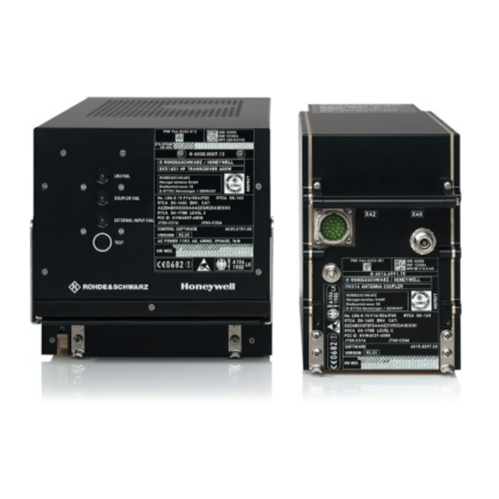
Honeywell XK516D1 Maintenance Manual (301 pages)
Brand:
Honeywell
| Category:
Transceiver
| Size: 9.82 MB
Table of Contents
Record of Revisions
2
Service Bulletin List
4
List of Effective Pages
7
Table of Contents
11
Introduction
17
Abbreviations and Acronyms
18
Highlights
21
Rear Panel
22
Electrical
23
Equipment Specifications
23
Operation of XK516D1 in Voice Mode
23
General Electrical and Mechanical Characteristics
25
Theory of Operation
31
General
31
Block Diagram (Simplified), Transceiver
32
Simplified Theory of Operation
33
Receiver/Exciter, A1
33
Interconnect Diagram, Transceiver
34
Functional Diagram, Receiver/Transmitter, A1
35
Block Diagram, Power Amplifier Board, A3
36
Transmit Mode
37
Power Amplifier, A3
37
Amplifier Board, A31
38
Harmonic Filter, A32
38
Power Supply, A4
38
LED Board, A5
39
Motherboard, A6
39
EMC Filter, A7
39
Controller D, A8, and Interface D, A9
39
Detailed Theory of Operation
40
ON/OFF Module, A15
40
Data Module
40
Synthesizer
40
Block Diagram, Synthesizer Loop 1
41
DDS (Digital Direct Synthesis)
47
Gate Arrays Register Address
48
Synthesizer D6 Divider Position
48
Block Diagram, Receiver Analog Front-End
49
Block Diagram, Transceiver Af/Digital Section
50
Receive Section
51
CM Monitoring
51
Transmission Section
54
SELCAL Reception
54
IF Processor, A12
54
Functional Description SSB Transmission Mode
54
Block Diagram, Exciter Analog Section
55
Functional Description AME Transmission Mode
56
Functional Description Monitoring Mode
56
From the 2Nd Intermediate Frequency to the Exciter Output
56
Test Operation
57
Airborne Data Link Processor (ADP), A2
57
Block Diagram, ADP, A2
58
Connector Pin Assignments, ADP, A2
59
Block Diagram, Amplifier Board, A31
61
Block Diagram, Amplifier Control, A33
66
Control Branches
68
Monitoring, CM, BIT
71
Low-Pass Filter
72
Directional Coupler
72
Block Diagram, Harmonic Filter, A32
73
Transmit/Receive Relay
74
BITREL Circuit-Breaker
74
Modem
74
Regulator Board, A41
74
Rectifiers and Series Regulators
75
Block Diagram, Regulator Board, A41
76
Continuous Monitoring, CM
77
Data Bus Controller
79
Data Bus Power Supply
79
LED Board, A5, and Motherboard, A6
80
Protective Resistors
80
Mains Filter, A42
80
Controller D, A8
81
Processor, D11
81
Chip Select Unit
82
Interrupt Controller
82
Bus Unit
82
Block Diagram, Controller D, A8
83
Assignment of Chip Select Signals
84
Eprom
84
Ram
84
Eeprom
84
Connection of an ASCII Terminal
85
Usart
85
Test Interface
85
Coupler Interface
85
A/D Converter
86
Parallel Input
86
ARINC Input
86
Format of an ARINC Word
86
Minimum Interval between Two ARINC Words
87
Assignment of ARINC Level to TTL Level
87
Linking Diagram of TTL Signals
87
Block Diagram, ARINC Input
88
ARINC Output
88
Level of Differential Output Signals
88
Block Diagram, ARINC Output
89
Parallel Output
89
Block Diagram, Interface D, A9
90
HF Modem, A10
91
Block Diagram, HF Modem, A10
92
Connector Pin Assignments, HF Modem, A10
93
ON off Module, A15
94
Front Panel
22
1 Introduction
95
2 Test Equipment
95
3 Test Conditions
95
Testing and Fault Isolation
95
4 Power Requirements
95
5 Automated Test Equipment (ATE) Setup
95
Software Installation
95
ATP Software Installation
96
CFDS Software Installation
96
6 HF Transceiver Test Setup
96
7 HF Transceiver ATP
97
Power Connection Integrity Check
97
8 Test Complete
98
Test Setup
99
Bit
104
Fault Isolation Aids
104
General
104
Methods of Fault Isolation
104
Bite
105
Test Points (TP)
105
Top Level Assembly Illustrated Parts List (IPL)
105
Transceiver Main Menu (ABD0048)
106
Transceiver Last Leg Report with no Fault Indicated (ABD0048)
107
Transceiver LRU Identification Menu (ABD0048)
107
Previous Leg Report with Failure Detected (ABD0048)
108
Transceiver Last Leg Report with Failures Detected (ABD0048)
108
Transceiver Ground Report with no Fault Detected (ABD0048)
109
Transceiver Ground Report with Failure Detected (ABD0048)
110
Transceiver Troubleshooting Data Menu with Failure Detected
111
Transceiver Ground Scanning Menu with no Fault Detected
112
Transceiver Ground Scanning Menu with Failure Detected
113
Table of Fault Messages
114
Manually-Initiated Test/Power up Test
115
Table of Test Results
115
Basic Voltage Test Procedure
116
Transceiver Test Menu with Failure Detected (ABD0048)
116
Transceiver Test Menu with no Fault Detected (ABD0048)
116
Basic Voltage Test Procedure
117
Transceiver Fault Isolation Chart
117
Procedure to Verify Failed Frequency with the CFDS Function
118
Sample Test Report
119
Transceiver Fault Isolation Procedure
129
Transceiver Fault Isolation Procedure
134
Schematic, XK516D1 400W HF Transceiver
139
Schematic, XK516D1 400W HF Transceiver
140
Schematic, Receiver/Exciter
141
Schematic, RF Board
143
Schematic, RF Board, A11
144
Schematic, if Processor
160
Schematic, if Processor, A12
161
Schematic, Subsynthesizer
165
Schematic, Subsynthesizer, A13
166
Schematic, on off Board
168
Schematic, on off Board
169
Schematic, Airborne Datalink Processor, A2
170
Schematic, Airborne Datalink Processor, A2
171
Schematic, HF Modem, A10
180
Schematic, HF Modem, A10
181
Schematic, Power Amplifier, A3
188
Schematic, Amplifier Board, A31
190
Schematic, Amplifier Board, A31
191
Schematic, Harmonic Filter, A32
196
Schematic, Harmonic Filter, A32
197
Schematic, Amplifier Control, A33
203
Schematic, Amplifier Control, A33
204
Schematic, Power Supply, A4
210
Schematic, Regulator Board, A41
212
Schematic, Regulator Board, A41
213
Schematic, Mains Filter, A42
218
Schematic, Mains Filter, A42
219
Schematic, LED Board, A5
220
Schematic, LED Board, A5
221
Schematic, Motherboard, A6
222
Schematic, Motherboard, A6
223
Schematic, EMC Filter, A7
233
Schematic, Controller D, A8
252
Schematic, Interface D, A9
260
Disassembly
274
General
274
Cleaning Materials
276
Repair Materials
281
Assembly Materials
284
Special Tools, Fixtures, and Equipment
288
Illustrated Parts List
290
Related Products
Honeywell XL4600SM
Honeywell X-DA4125
Honeywell XNX-AMSV Series
Honeywell XNX-AMSE Series
Honeywell XNX-AMAE Series
Honeywell XNX-BTAI Series
Honeywell XNX-BTSV Series
Honeywell X-DCS3000
Honeywell XIO-CCM-S-H
Honeywell X-DA1500EN
Honeywell Categories
Thermostat
Controller
Control Unit
Security Camera
Accessories
More Honeywell Manuals