
Related Manuals for GE KVGC 202


Summary of Contents for GE KVGC 202
- Page 1 GE Energy Connections Grid Solutions KVGC Technical Manual Voltage Regulating Control Relays Publication reference: KVGC202/EN M/H11...
-
Page 3: Table Of Contents
Technical Manual KVCG202/EN M/H11 KVGC202 CONTENTS INTRODUCTION Introduction Using the manual Models available HANDLING AND INSTALLATION General considerations 2.1.1 Receipt of product 2.1.2 Electrostatic discharge (ESD) Handling of electronic equipment Mounting Unpacking Storage RELAY DESCRIPTION Relay description User interface 3.2.1 Frontplate layout 3.2.2 LED indications... -
Page 4: Control
KVCG202/EN M/H11 Technical Manual KVGC202 3.4.14 Setting output masks 3.4.15 Resetting values 3.4.16 Resetting CONTROL LED indication External connections 3.5.1 Auxiliary supply 3.5.2 Logic control inputs 3.5.3 Analogue inputs 3.5.4 Output relays 3.5.5 Setting the relay with a PC or Laptop Alarm flags APPLICATION OF CONTROL FUNCTIONS Configuring the relay... - Page 5 Technical Manual KVCG202/EN M/H11 KVGC202 4.9.1 Tap changer maintenance 4.9.1.1 Tap change operations counter 4.9.1.2 Frequent operations monitor 4.9.1.3 Tap changer failure detection 4.10 Load shedding/boosting RELAY SETTINGS Relay settings 5.1.1 Setting voltage (Vs) 5.1.2 Deadband (dVs) 5.1.3 Initial time delay setting (tINIT) 5.1.4 Inter-tap delay (tINTER) 5.1.5...
- Page 6 KVCG202/EN M/H11 Technical Manual KVGC202 6.2.2 Time tagging of event records 6.2.3 Accessing and resetting event records 6.2.4 Recorded times Alarm records 6.3.1 Watchdog 6.3.2 Alarm indication 6.3.3 Blocked indication Functional alarms 6.4.1 Raise/lower volts indication 6.4.2 Blocked indication 6.4.3 Undervoltage blocking (V<<) 6.4.4 Undervoltage detection (V<)
- Page 7 Technical Manual KVCG202/EN M/H11 KVGC202 TECHNICAL DATA Ratings 8.1.1 Inputs Outputs Burdens 8.3.1 Current circuits 8.3.2 Reference voltage 8.3.3 Auxiliary voltage 8.3.4 Opto-isolated inputs Control function setting ranges Time delay setting ranges 8.5.1 Inverse time delay 8.5.2 Definite time delay Supervision function settings Transformer ratios Measurement (displayed)
- Page 8 KVCG202/EN M/H11 Technical Manual KVGC202 8.20 Mechanical environment 8.20.1 Vibration IEC 60255-21-1:1988 8.20.2 Shock and bump IEC 60255-21 2:1988 8.20.3 Seismic IEC 60255-21-3:1993 8.20.4 Mechanical durability 8.21 Model numbers 8.22 Frequency response COMMISSIONING, PROBLEM SOLVING AND MAINTENANCE Commissioning preliminaries 9.1.1 Quick guide to local menu control 9.1.2 Terminal allocation...
- Page 9 Technical Manual KVCG202/EN M/H11 KVGC202 9.8.1 Password lost or not accepted 9.8.2 Software link settings 9.8.2.1 System links 9.8.2.2 Control links 9.8.2.3 Logic links 9.8.2.4 Second setting group not displayed or working 9.8.2.5 Software links cannot be changed 9.8.3 Alarms 9.8.3.1 Watchdog alarm 9.8.3.2...
- Page 10 KVCG202/EN M/H11 Technical Manual KVGC202...
-
Page 11: Introduction
Technical Manual KVCG202/EN M/H11 KVGC202 INTRODUCTION Introduction The KVGC202 relay is the K Range version of the MVGC voltage regulating relay based on the K Range series 2 relays. The KVGC202 has retained the existing functionality of the MVGC relay and additional functionalities and features have been added to the relay, to allow greater flexibility. -
Page 12: Models Available
Appendices include relay time characteristic curve, logic diagram, connection diagrams and commissioning test records. Index Provides the user with page references for quick access to selected topics. Models available The following models are available: KVGC 202 01N21GE_ 24–125V rated model KVGC 202 01N51GE_ 48–250V rated model... -
Page 13: Handling And Installation
Technical Manual KVCG202/EN M/H11 KVGC202 HANDLING AND INSTALLATION General considerations 2.1.1 Receipt of product Although the product is generally of robust construction, careful treatment is required prior to installation on site. Upon receipt, the product should be examined immediately, to ensure no damage has been sustained in transit. -
Page 14: Mounting
KVCG202/EN M/H11 Technical Manual KVGC202 electronic circuitry, or modification work, should be carried out in a Special Handling Area such as described in the above-mentioned BS and IEC documents. Mounting Products are dispatched, either individually, or as part of a panel/rack assembly. If loose products are to be assembled into a scheme, then construction details can be found in Publication R7012. -
Page 15: Relay Description
Technical Manual KVCG202/EN M/H11 KVGC202 RELAY DESCRIPTION Relay description The KVGC202 voltage regulating relay use numerical techniques to derive control functions. Six multiplexed analogue inputs are used, sampled eight times per power frequency cycle. The Fourier derived power frequency component returns the rms value of the measured quantity. -
Page 16: Frontplate Layout
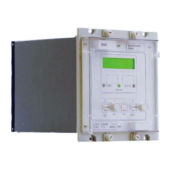
KVCG202/EN M/H11 Technical Manual KVGC202 3.2.1 Frontplate layout Figure 1: Front plate layout The front plate of the relay carries a liquid crystal display (LCD) on which data such as settings, measured values and information for the control conditions can be viewed. The data is accessed through a menu system. -
Page 17: Keypad
Technical Manual KVCG202/EN M/H11 KVGC202 3.2.3 Keypad The four keys perform the following functions: – function select/digit select key/next column – put in setting mode/increment value/accept key/previous column [–] – put in setting mode/decrement value/reject key/next column – reset/escape/change default display key Note: Only the [F] and [0] keys are accessible when the relay cover is in place. -
Page 18: Accessing The Menu
KVCG202/EN M/H11 Technical Manual KVGC202 Following the initiation of a tap change operation the display will change to show the time remaining before the next tap change is due. It will do this by temporarily changing to default display 6, alarm status/raise volts/lower volts and time remaining. This change will not occur if display 7 is selected, as this option already displays the time remaining. -
Page 19: Menu Columns
Technical Manual KVCG202/EN M/H11 KVGC202 3.3.4 Menu columns Col No Heading Description SYSTEM DATA Settings and data for the system – relay and serial communications. STATUS Settings for tap control modes MEASURE Display of directly measured and calculated quantities CONTROL 1 Settings for group 1 miscellaneous control functions LOGIC 1 Settings for group 1 miscellaneous logic functions... - Page 20 KVCG202/EN M/H11 Technical Manual KVGC202 Cell Text Status Description 000D Ctrl Status READ Binary word used to indicate the status of control data 000E Grp now READ Indicates the active setting group 000F LSB Stage READ Indicates the last received load shedding command 0011 Software READ...
- Page 21 Technical Manual KVCG202/EN M/H11 KVGC202 An address between 1 and 254 that identifies the relay when interconnected by a communication bus. These addresses may be shared between several communication buses and therefore not all these addresses will necessarily be available on the bus to which the relay is connected.
-
Page 22: Status
KVCG202/EN M/H11 Technical Manual KVGC202 3.3.6 Status Cell Text Status Description 0100 STATUS Column heading 0101 Control READ 1 = Remote ; 2 = Local 0102 Mode 1 = Manual ; 2 = Auto 0103 No Operation ; Raise V ; Lower V 0104 ST Links 0 = Blocked... -
Page 23: Logic 1
Technical Manual KVCG202/EN M/H11 KVGC202 Cell Text Status Description 0205 Power Fact READ Calculated from a/–90° with respect to Vbc 0206 Frequency READ Measured frequency 0207 TapPosition READ Actual tap position 0208 Highest tap RESE Highest tap used since last reset 0209 Lowest tap RESE... -
Page 24: Control 2
KVCG202/EN M/H11 Technical Manual KVGC202 Cell Text Status Description 1 = block for excessive load current L> blk Total opsBlk 1 = block for excessive number of operations Freq opsBlk 1 = block for frequent operation 1 = block operation for reverse current flow rev blk Runaway blk 1 = block for tap change runaway... -
Page 25: Logic 2
Technical Manual KVCG202/EN M/H11 KVGC202 Cell Text Status Description 050C tINTER Inter tap delay 050D tPULSE Tap pulse duration 050E Level 1 Load shedding/boosting level 1 050F Level 2 Load shedding/boosting level 2 0510 Level 3 Load shedding/boosting level 3 0511 tTapChange Time between tap position indications... -
Page 26: Input Masks
KVCG202/EN M/H11 Technical Manual KVGC202 3.3.12 Input masks Cell Text Status Description 0700 INPUT MASKS READ Column heading 0701 Remote Logic input for remote selection of Auto/Manual mode 0702 Automatic Logic input to select automatic mode 0703 Manual Logic input to select manual mode 0704 Raise V Logic input to manually initiate signal to raise the tap... -
Page 27: Changing Text And Settings
Technical Manual KVCG202/EN M/H11 KVGC202 Cell Text Status Description 0815 Select tst rlys Select relays to operate when relay test is selected 0816 Test Relays = [0] Press [0] key to close relays selected Changing text and settings Settings and text in certain cells of the menu can be changed via the user interface. To do this the cover must be removed from the front of the relay so that the [+] and [–] keys can be accessed. -
Page 28: To Enter Setting Mode
KVCG202/EN M/H11 Technical Manual KVGC202 [F]long – means press F key and hold for longer than 1 second. [F]short – means press F key and hold for less than 1 second. – means press the F key length of time does not change the response. [0]long –... -
Page 29: Password Protection
Technical Manual KVCG202/EN M/H11 KVGC202 3.4.5 Password protection Password protection is provided for the configuration settings of the relay. This includes CT and VT ratios, function links, input masks and relay masks. Any accidental change to configuration could seriously affect the ability of the relay to perform its intended functions, whereas, a setting error may only cause a grading problem. -
Page 30: Restoration Of Password Protection
KVCG202/EN M/H11 Technical Manual KVGC202 Note: Make sure the new password has been written down before it is entered and that the password being entered agrees with the written copy before accepting it. If the new password is not entered correctly you may be denied access in the future. If the password is lost a unique back-up password for that relay can be provided from the factory, or certain agents, if the serial number of the product is quoted. -
Page 31: Setting Input Masks
Technical Manual KVCG202/EN M/H11 KVGC202 then decrementing or incrementing the address. Then exit setting mode as described in Chapter 3.4.3. There is a feature in Courier that can be used to automatically allocate an address to the relay, provided the master station software supports this feature. It is recommended that the user enters a name for the plant reference in the appropriate menu cell and then sets the address manually to “0”. -
Page 32: Auxiliary Supply
KVCG202/EN M/H11 Technical Manual KVGC202 Function Terminal Function Earth Terminal – – Not used Watchdog Relay Watchdog Relay (Break contact) (Make contact) 48V Field Voltage [–] 48V Field Voltage Not used – – Not used Not used – – Not used Auxiliary Supply (–) Auxiliary Supply (–dc or ac) -
Page 33: Logic Control Inputs
Technical Manual KVCG202/EN M/H11 KVGC202 will be 50V dc or 110V ac because these values fall within both of the auxiliary voltage ranges. The supply should be connected to terminals 13 and 14 only. To avoid any confusion it is recommended that the polarity of any applied voltage is kept to the Midos standard: for dc supplies the positive lead connected to terminal 13 and the negative to terminal for ac supplies the live lead is connected to terminal 13 and the neutral lead to... -
Page 34: Analogue Inputs
KVCG202/EN M/H11 Technical Manual KVGC202 Figure 3: Example connection of logic inputs 3.5.3 Analogue inputs The relay has six analogue inputs, two on the microprocessor board and four on the auxiliary expansion board. Each is fed via an input transducer, a low pass filter and a three range scaling amplifier. -
Page 35: Alarm Flags
Technical Manual KVCG202/EN M/H11 KVGC202 The communication connections and available software are covered in Chapter 7. Alarm flags A full list of the alarm flags will be found in Chapter 3.3.5 and they are located in cell 0022 of the SYSTEM DATA column of the menu. They consist of nine characters that may be either “1”... -
Page 36: Application Of Control Functions
KVCG202/EN M/H11 Technical Manual KVGC202 APPLICATION OF CONTROL FUNCTIONS The settings that customise the relay for a particular application are referred to as the configuration. They include the function links, input masks, relay masks, etc and they are password protected to prevent them being changed accidentally. Together these settings select the functions that are to be made available and how they are to be interconnected. -
Page 37: Logic Links (Log)
Technical Manual KVCG202/EN M/H11 KVGC202 The following options are available via links SD0 to SD7: Not used Rem Cntrl 1 = enable remote control Rem LSB 1 = enable load shedding/boost Rem Grp2 1 = enable remote change to group2 settings En Grp2 1 = enable group 2 settings 0 = hide group 2 settings... -
Page 38: Control Links (Ctl)
KVCG202/EN M/H11 Technical Manual KVGC202 4.2.3 Control links (CTL) The Control Links under the CONTROL menu column heading customise the auxiliary functions of the relay. Put the relay into setting mode by pressing the [+] key. Step through the function links with the [F] key and set the links for the options required. CTL0 Not used CTL1... -
Page 39: Applications
Technical Manual KVCG202/EN M/H11 KVGC202 SD5=1 – setting group 2. If SD6=1 then reverse current will automatically select group 2 settings. Note: If [SD4] = 0 then the group 2 settings will be hidden and group 1 will be active by default. Link [SD4] must be set to “1”... -
Page 40: Initial Delay (Tinit)
KVCG202/EN M/H11 Technical Manual KVGC202 The relay incorporates an initial time delay before the initiation of a tap change sequence. On expiration of the time delay the appropriate ‘Raise Volts’ or ‘Lower Volts’ output relay operates to control the tap changer. The initial time delay is the time delay to initiate the first tap change step in a multiple sequence. -
Page 41: Intertap Delay
Technical Manual KVCG202/EN M/H11 KVGC202 4.4.3.3 Intertap Delay If additional tap changes are required to bring the voltage back within the deadband limits a definite intertap delay determines the delay between subsequent tap change initiations. The inter-tap delay will start after the tap pulse duration has elapsed. While the regulated voltage remains outside the deadband the output relay will continue to give pulsed closure for the tap pulse duration at intervals determined by the Intertap Delay. -
Page 42: Method
KVCG202/EN M/H11 Technical Manual KVGC202 The normally open contact is usually operated by direct movement of the tap changer’s motor mechanism using the directional sequence switch or an interposing auxiliary relay. In older static designs of VRR a contact which opened during each tap change step was connected to isolate the measuring voltage to the VRR. -
Page 43: Auto, Manual And Remote Operation Modes
Technical Manual KVCG202/EN M/H11 KVGC202 Where: = primary rated current of the line CT = resistive component of line impedance = reactive component of line impedance As can be seen from the above equations the KVGC is set in terms of the resistive and reactive volt drop that will occur when rated current is applied to the relay. -
Page 44: Remote Change Of Operating Mode
KVCG202/EN M/H11 Technical Manual KVGC202 The remote selection of AUTO and MANUAL modes can only be made when link [SD1] is set to ‘1’ or the REMOTE opto-input is energised. When switched from a locally selected mode to remote, the relay remains in the last locally selected mode until a new mode is selected remotely. -
Page 45: Master-Follower Schemes
Technical Manual KVCG202/EN M/H11 KVGC202 Figure 10: Operation of 2 transformers connected in parallel on local busbars The total load current is shared between the two transformers as the inverse ratio of impedances and for similar transformers I1 = I2 and IL = 2 I1 = 2 I2 There are several methods of controlling paralleled transformer groups and these may be classified into two categories. -
Page 46: Instability Of Individually Controlled Parallel Transformers
KVCG202/EN M/H11 Technical Manual KVGC202 Note, the minimum operating voltage of the opto inputs is >35 V and so the maximum limiting series lead resistance for a single opto input is 2000 ohms. In general master-follower schemes are not suited for parallel control of transformers which have dissimilar tap step increments or number of taps. -
Page 47: Effect Of Circulating Current On Ldc
Technical Manual KVCG202/EN M/H11 KVGC202 1. Master-follower 2. Circulating current detection 3. Negative reactance compounding 4.7.2.2 Effect of circulating current on LDC Consider two similar transformers connected in parallel as shown in Figure 11. The busbar voltage as seen by both VRR’s is Vbus. The LDC settings are selected such that Vr = IL.R Vxl = IL.X Where R is the resistive component of the line and X is the reactive component of the line... - Page 48 KVCG202/EN M/H11 Technical Manual KVGC202 Figure 11: Circulating currents due to tap disparity Figure 12: Voltages with transformers T1 and T2 on the same tap position Figure 13: Effects of circulating currents on LDC IL-Ic (Volts Low)
-
Page 49: Negative Reactance Compounding
Technical Manual KVCG202/EN M/H11 KVGC202 Figure 14: Effects of circulating currents on LDC IL+Ic (Volts High) 4.7.3 Negative reactance compounding Since the effect of Ic on the Vxl setting is the main contributing factor to stability, a reversal of the Vxl setting would produce components –IL.XL and –Ic.XL. The overall effect is to obtain stable operation as the transformers are being driven towards the same tap position. - Page 50 KVCG202/EN M/H11 Technical Manual KVGC202 Figure 16: Negative reactance control 2 Figures 15 and 16 mimic Figures 13 and 14 except that in this case all the compensation elements which are reactive have been reversed, the resistive elements being unchanged. It can now be seen that the transformer with a low volts condition is presenting a regulating voltage Vreg which is lower than Vrem (the required voltage) and hence a raise volts command is given.
- Page 51 Technical Manual KVCG202/EN M/H11 KVGC202 compensation on the relay to correct for the additional error that would occur because of this. This is shown in Figure 18. In this example Vr is set to: 3 x Ip x XT tan φ Vr = VT_ratio where Cosϕ...
-
Page 52: Circulating Current Control
KVCG202/EN M/H11 Technical Manual KVGC202 3 x IP x (RLcos φ + XLsin φ + XTsin φ) Vr = VT_ratio where Cosϕ = power factor of the load Figure 20: Low Power Factor with Negative Reactance Control and LDC 2 4.7.4 Circulating current control An alternative method of parallel control of transformers are the circulating current control... -
Page 53: Independent/Parallel Control
Technical Manual KVCG202/EN M/H11 KVGC202 the tap changers are forced to be in step with each other if the compensating voltage, Vc, is large enough to take the regulated voltage outside the deadband. The circulating current inputs from the line CTs for the KVGC202 are terminals 23-24 for 1A rated CTs and 25-26 for 5A rated CTs. -
Page 54: Circulating Current Control With Ldc
KVCG202/EN M/H11 Technical Manual KVGC202 Figure 23: Shorting of Circulating Current Control Pilot Wires Contact A – OPEN for parallel control CLOSED for independent control Contact B – OPEN when local LV CB is closed CLOSED when local LV CB is open 4.7.4.2 Circulating current control with LDC Where parallel transformers feed distribution lines and pilot wires are connected to... - Page 55 Technical Manual KVCG202/EN M/H11 KVGC202 Figure 24: Parallel connection of LDC circuits The following notes demonstrate how the LDC CTs may be paralleled on a KVGC202 relay. 2RL1 = Lead loop resistance between CT1 and AVR1 plus resistance of AVR circulating current CT input, KVGC202 terminals 23 and 24 for In=1A or terminals 25 and 26 for In=5A.
- Page 56 KVCG202/EN M/H11 Technical Manual KVGC202 Figure 25: Equivalent circuit diagram for two KVGC202 relays with paralleled LDC inputs = I1 + I2 V = I1 R V = (2I – I1) (2R I1 RLDC = (2I – I1) (2R I1 = + (2R Simplifying ...
- Page 57 Technical Manual KVCG202/EN M/H11 KVGC202 Example 1: Application of 2 VRRs (1A rated) with direct paralleling = 50m 2.5mm Cu = 0.37Ω RLDC 0.007Ω <0.0526 where LDC' LDC' ' > 19R ' > 7.03 Therefore: > 7.03 – 0.007 > 7.023 Choose a value of Rs = 7Ω.
- Page 58 KVCG202/EN M/H11 Technical Manual KVGC202 Figure 27: ICT2 RICT2 Therefore: ICT2 ICT2 KVGC202 burden for LDC = 0.007Ω at In Therefore: RLDC = 0.007Ω <0.0526 Therefore: ICT2 <0.0526 ICT1 or RLDC must be increased to RLDC' via a series resistor so that: ...
- Page 59 Technical Manual KVCG202/EN M/H11 KVGC202 Therefore, minimum current rating = 50W and, allowing a 50% derating of the component, a 100W resistor is required. Therefore use RS = 0.5 Ω 100W. Note: See short time current withstand note given in example 1. 4.7.4.2.2 Series connection of LDC circuits As an alternative to the parallel connection of LDC circuits, the LDC circuits can be connected in series, see Figure 29.
-
Page 60: Supervision Functions Of A Vrr
KVCG202/EN M/H11 Technical Manual KVGC202 With negative reactance compounding use of a large negative reactance component will give good performance in terms of keeping tapchangers in step but will increase the susceptibility of the tapchangers to tap erroneously. This is due to increased errors in the regulated voltage caused by changes in the power factor. -
Page 61: Undervoltage Blocking (V<<)
Technical Manual KVCG202/EN M/H11 KVGC202 4.8.3 Undervoltage blocking (V<<) If the system voltage falls below typically 80% Vs, it is necessary to inhibit the relay ‘Raise V’ and ‘Lower V’ outputs. This is needed to prevent operation for fault conditions on or through the transformer, where the current through the tap changer exceeds the switching capacity of the tap changer mechanism. - Page 62 KVCG202/EN M/H11 Technical Manual KVGC202 external voltage VT. The advantage of using the external voltage is that the tap position will be indicated even if the transformer is de-energised. The tap position is determined by applying Vph-ph from a VT or an external voltage to a potential divider and determining the tap position from the output voltage which is fed to the relay on terminals 19-20.
- Page 63 Technical Manual KVCG202/EN M/H11 KVGC202 Figure 29: Connection of 22 tap potential divider to KVGC with VT voltage input...
- Page 64 KVCG202/EN M/H11 Technical Manual KVGC202 External Supply Figure 30: Connection of 22 tap potential divider to KVGC with AC External supply...
-
Page 65: Tap Changer Maintenance
Technical Manual KVCG202/EN M/H11 KVGC202 Figure 31: Connection of 40 tap potential divider to KVGC with VT voltage input 4.9.1 Tap changer maintenance 4.9.1.1 Tap change operations counter The relay provides an indication of the maximum number of tap changer operations. The user may configure the logic to initiate an alarm through the relay masks if the number of tap change operations has exceeded a preset value. -
Page 66: Tap Changer Failure Detection
KVCG202/EN M/H11 Technical Manual KVGC202 4.9.1.3 Tap changer failure detection The Tap Changer Failure feature is provided to detect failure of a tap changer to respond to Raise/Lower commands of the relay. Tap changer failure is detected by checking if the regulated voltage fails to come within the deadband limits within the tFAIL time delay in response to a valid raise/lower command. -
Page 67: Relay Settings
Technical Manual KVCG202/EN M/H11 KVGC202 RELAY SETTINGS Relay settings All the settings can be entered into the relay via the front keypad or using a PC with a K- Bus connection. The selection can be made in the menu columns for settings, but password might be required before some settings can be entered. -
Page 68: Setting Voltage (Vs)
KVCG202/EN M/H11 Technical Manual KVGC202 Setting Symbols KVGC adjustment range In steps of Tap change indication time t Tap change 1 – 3 secs 0.1 secs 5.1.1 Setting voltage (Vs) The setting voltage can be selected between 90 and 139V in 0.1 volt steps. The relay compares the system input voltage with this setting voltage and provides raise or lower signals to the tap changer to control the system voltage to be within the set deadband limits. -
Page 69: Tap Pulse Duration (Tpulse)
Technical Manual KVCG202/EN M/H11 KVGC202 5.1.5 Tap pulse duration (tPULSE) The tap pulse duration can be set between 0.5 to 5 seconds. It is initiated to ‘Raise volts’ or ‘Lower volts’ during multiple tap change sequence. 5.1.6 Line drop compensation (Vr and Vxl) The resistive and reactive controls are set such that the voltage at a point remote to the tap changing transformer can be regulated for varying load conditions. -
Page 70: Load Shedding/Boosting
KVCG202/EN M/H11 Technical Manual KVGC202 5.1.8 Load shedding/boosting The effective regulated voltage can be lowered or raised by means of the load shedding/boosting option. Three programmable levels are available which can be selected either remotely via K-Bus or by energising one of the three opto inputs channels. Each level can be set between 0 and ±10% and the selected values can be viewed under the SYSTEM DATA heading of the menu system. -
Page 71: Total Taps Available (Tpavail)
Technical Manual KVCG202/EN M/H11 KVGC202 5.1.17 Total taps available (TpAvail) The total number of taps available can be set between 1 and 40 if the VT is used for tap position indication (TPI) or 1-30 if an external voltage is used. This setting should be set to indicate the number of resistors used in the TPI resistor box. -
Page 72: Controlled Change Of Setting Group
KVCG202/EN M/H11 Technical Manual KVGC202 5.2.3 Controlled change of setting group Link SD4 must be set to “1” to make the second setting group active. Now energising a logic input allocated in mask [070A STG GRP2] will select setting group 2. The logic input could be energised via the contacts of one of the output relays so that change of setting group will be in response to some control or supervision functions. -
Page 73: Initial Logic Settings
Technical Manual KVCG202/EN M/H11 KVGC202 5.3.4 Initial logic settings Logic Symbol Factory Settings Undervoltage total inhibit level (% of Vs) V<< Undervoltage blocking limit V< 100V Overvoltage blocking limit V> 120V Over/under voltage blocking timer tVTotal time outside dead band to = failure tFAIL 180s Excessive circulating current threshold... - Page 74 KVCG202/EN M/H11 Technical Manual KVGC202 RELAY MASKS DEFAULT SETTINGS V> 0000000 V< 00100000 Tap Fail 01000000 10000000 c> 10000000 L> Il< 00000000 TotalOps> 00000000 FreqOps 00000000 00000000 RUN - AWAY 00000000 Tap Limit 00000000 Tap Odd 00000000 Tap Even 00000000 Auto Mode 00000000 Manual Mode...
-
Page 75: Measurement, Records And Alarms
Technical Manual KVCG202/EN M/H11 KVGC202 MEASUREMENT, RECORDS AND ALARMS Measurement The measured voltage (Vbc) and phase A current values ( L) and ( c) are available in real time. The rolling average calculation is used to provide a stable displayed reading of the measured values obtained from the sampled waveforms. -
Page 76: Tap Position
KVCG202/EN M/H11 Technical Manual KVGC202 The power factor is calculated by rotating the load current by –90° to make it relative to Vbc. The calculated power pf is converted into a ‘numeric quantity (in the form of ‘Mantissa, Sign, Exponent, Units’) to allow it to be used by the measurement display. The power factor is stored in cell location 0205. -
Page 77: Triggering Event Records
Technical Manual KVCG202/EN M/H11 KVGC202 6.2.1 Triggering event records Event records are triggered automatically in response to the functions listed in Chapter 6.2. 6.2.2 Time tagging of event records The KVGC202 relay does not have a real time clock. Instead, it has a free-running 32-bit counter that increments every 1 millisecond. -
Page 78: Alarm Indication
KVCG202/EN M/H11 Technical Manual KVGC202 6.3.2 Alarm indication The alarm LED will flash when the password has been entered. It will be lit and remain steady when an internal fault has been detected by its self test routine. The alarm flags can then be accessed to determine the fault, provided the relay is still able to perform this function. -
Page 79: Overvoltage Detection (V>)
Technical Manual KVCG202/EN M/H11 KVGC202 6.4.5 Overvoltage detection (V>) The overvoltage detector will block operations that raise the voltage, to prevent excessive voltage on busbars local to the transformer. V> output relay allocated in the relay mask will pick up the overvoltage detection condition to give the alarm indication. -
Page 80: Tap Position Indication
KVCG202/EN M/H11 Technical Manual KVGC202 6.4.11 Tap position indication The relay provides an indication of the actual tap position. If the tap position read exceeds the minimum (Tp<) and maximum (Tp>) thresholds, an output relay (TapLimit) allocated in the relay mask operates to give an alarm indication. 6.4.12 Tap change operations counter The relay provides an indication of the maximum number of counts of the tap changer... -
Page 81: Control Functions And Serial Communications
Technical Manual KVCG202/EN M/H11 KVGC202 CONTROL FUNCTIONS AND SERIAL COMMUNICATIONS Courier language protocol Serial communications are supported over K-Bus, a multi-drop network that readily interfaces to IEC 60870-5 FT1.2 Standards. The language and protocol used for communication is Courier. It has been especially developed to enable generic master station programs to access many different types of relay without the continual need to modify the master station program for each relay type. -
Page 82: K-Bus Connections
KVCG202/EN M/H11 Technical Manual KVGC202 Figure 33: Basic communication system 7.2.2 K-Bus connections Connection to the K-Bus Port is by standard Midos 4mm screw terminals or snap-on connectors. A twisted pair of wires is all that is required; the polarity of connection is not important. -
Page 83: Ancillary Equipment
Technical Manual KVCG202/EN M/H11 KVGC202 7.2.3 Ancillary equipment The minimum requirement to communicate with the relay is a K-Bus/IEC 60870-5 converter box type KITZ and suitable software to run on an IBM or compatible personal computer. RS232 interconnection lead for connecting the KITZ to a personal computer (PC) and software as described in Chapter 7.3. -
Page 84: Pc Requirements
KVCG202/EN M/H11 Technical Manual KVGC202 7.3.4 PC requirements To operate fully, the above programs require: IBM PC/XT/AT/PS2 or true compatible 640 kBytes of main memory RAM Graphics adapter CGA, EGA, VGA or MDA Serial adapter port configured as COM1 or COM2 (RS232) Floppy disc drive 3.5 inch MS-DOS 3.2 or later/IBM PC-DOS 3.2 or later Parallel printer port for optional printer... -
Page 85: Data For System Integration
Technical Manual KVCG202/EN M/H11 KVGC202 Data for system integration 7.4.1 Relay address The relay can have any address from 1 to 254 inclusive. Address 255 is the global address that all relays, or other slave devices, respond to. The Courier protocol specifies that no reply shall be issued by a slave device in response to a global message. -
Page 86: Control Status Word
KVCG202/EN M/H11 Technical Manual KVGC202 7.4.5 Control status word The control status word will be found in menu cell 000D. It is used to transfer control information from the slave device to the master control unit. 7.4.6 Logic input status word The status of the logic control inputs can be observed by polling menu cell 0020, where the lowest 8 bits of the returned value indicates the status of each of the 8 logic inputs. -
Page 87: Setting Control
Technical Manual KVCG202/EN M/H11 KVGC202 Setting control Control functions via a KVGC202 relay can be performed over the serial communication link. They include change of relay settings, change of setting groups, remote control of the operating modes. Remote control is restricted to those functions that have been selected in the relays menu table and the selection cannot be changed without entering the password. -
Page 88: Local Control Of Loadshedding/Boosting
KVCG202/EN M/H11 Technical Manual KVGC202 The relay will only respond to the commands via serial port if link SD2=1. Setting SD2=0 inhibits all remote commands over the serial port. The following cell locations are allocated to store three levels of loadshedding/boosting in the CONTROL column of the menu system. -
Page 89: Technical Data
Technical Manual KVCG202/EN M/H11 KVGC202 TECHNICAL DATA Ratings 8.1.1 Inputs Continuous 3 sec 1 sec AC current ( Rated ( Auxiliary Voltage Input Rated (Vn) Continuous 10 sec (Line) (xVn) (xVn) Operative range Auxiliary voltage Rated voltage DC supply AC supply Crest (Vx) Auxiliary powered... -
Page 90: Auxiliary Voltage
KVCG202/EN M/H11 Technical Manual KVGC202 8.3.3 Auxiliary voltage The burden on the auxiliary supply depends upon the number of output relays and control inputs energised. DC supply 2.5 – 6.0W at Vx max with no output relays or logic inputs energized 4.0 –... -
Page 91: Definite Time Delay
Technical Manual KVCG202/EN M/H11 KVGC202 8.5.2 Definite time delay Setting Symbols Setting range Step size Initial time (definite) tINIT 0 – 20 secs 1 sec 20 – 300 secs 10 secs Supervision function settings Setting Symbols Setting range Step size Undervoltage blocking V<<... -
Page 92: Directional
KVCG202/EN M/H11 Technical Manual KVGC202 8.9.3 Directional Operating boundary 0 – 180° accuracy ±3° PU – DO differential less than 3° (typically <1°) 8.9.4 Measurements Measured voltage ±2% Vn (typical) ±0.3% Vn over the range 70 – 160V (typical) Load current ±2% n (typical) Circulating current... -
Page 93: Opto-Isolated Inputs
Technical Manual KVCG202/EN M/H11 KVGC202 8.11 Opto-isolated inputs Capture time 12.5 ±2.5ms at 50Hz 10.4 ±2.1ms at 60Hz Release time 12.5 ±2.5ms at 50Hz 10.4 ±2.1ms at 60Hz Minimum operating voltage >35V dc Maximum operating voltage 50Vdc Input resistance 10kΩ (add 12kΩ for every additional 50V inexcess of 50V) Maximum series lead resistance 2kΩ... -
Page 94: Current Transformer Requirements
KVCG202/EN M/H11 Technical Manual KVGC202 8.15 Current transformer requirements Relay and CT Nominal output class Acuracy class Accuracy limit factor secondary rated (VA) (x rated current 1/5A 8.16 High voltage withstand 8.16.1 Dielectric withstand IEC 255-5:1977 2.0kV rms for 1 minute between all terminals connected together and case earth except terminal 1. -
Page 95: Mechanical Environment
Technical Manual KVCG202/EN M/H11 KVGC202 8.17.8 Conducted immunity ENV50141:1993 Level 3 – 10V rms 0.15MHz - 80MHz. 8.17.9 Radiated emissions EN55011:1991 Group 1 – class A limits (30MHz - 1000MHz). 8.17.10 Conducted emissions EN55011:1991 Group 1 – class A limits (0.15MHz - 30MHz). 8.18 ANSI/IEEE Specifications 8.18.1... -
Page 96: Model Numbers
KVCG202/EN M/H11 Technical Manual KVGC202 8.21 Model numbers Relay type: K V G C 2 0 2 Configuration: Standard Case size: Size 6 MIDOS Flush Mounting Auxiliary voltage: 24/125V 48/250V Operating voltage: 110V ac/50 – 60Hz C.T. Rating: 5/1A (User selectable) Language: English French... - Page 97 Technical Manual KVCG202/EN M/H11 KVGC202 Measurement is based on the Fourier derived value of the fundamental component of line L), circulating current ( c), Tap position indication voltage (VTPI) and low accuracy system voltage input (Vbc). The diagram above shows the frequency response that results from this filtering.
-
Page 98: Commissioning Preliminaries
KVCG202/EN M/H11 Technical Manual KVGC202 COMMISSIONING, PROBLEM SOLVING AND MAINTENANCE Commissioning preliminaries The safety section should be read before commencing any work on the equipment. When commissioning a KVGC202 relay for the first time, the engineers should allow an hour to get familiar with the menu. Please read Chapter 3 Section 3.3 which provides simple instructions for negotiating the relay menu using the push buttons [F] [+] [–] and [0] on the front of the relay. -
Page 99: Test Block
Technical Manual KVCG202/EN M/H11 KVGC202 9.1.7 Test block If the MMLG test block is provided, the connections should be checked to the scheme diagram, particularly that the supply connections are to the live side of the test block (coloured orange) and with the terminals allocated odd numbers (1, 3, 5, 7 etc.). The auxiliary supply is normally routed via terminals 13 (+) and 15 (–), but check against the schematic diagram for the installation. -
Page 100: Auxiliary Supply Tests
KVCG202/EN M/H11 Technical Manual KVGC202 Auxiliary supply tests 9.3.1 Auxiliary supply The relay can be operated from either an ac or a dc auxiliary supply but the incoming voltage must be within the operating range specified in Table 1. Relay rating (V) DC operating AC operating Maximum crest... -
Page 101: Selective Logic Functions To Be Tested
Technical Manual KVCG202/EN M/H11 KVGC202 There are two setting groups available, this allows the user to set Group 1 to normal operating conditions while Group 2 can be set to cover abnormal operating conditions. The factory settings can be changed to the customer settings by referring to the instructions detailed in Chapter 3 Section 3.4. -
Page 102: Control Functions
KVCG202/EN M/H11 Technical Manual KVGC202 Control functions Reference should be made to Appendix 3 for the application diagram used for the following tests. The relay should be commissioned with the settings calculated for the application. 9.6.1 Regulated Voltage setting V and Dead Band dV The relay should be commissioned with the settings calculated for the application. -
Page 103: Integrated Timer
Technical Manual KVCG202/EN M/H11 KVGC202 For test 3 and 6 connect L2 OPTO (terminal 50) to switch S1. Set the load shedding/boosting setting level 1 to –3%, level 2 to –6% level 3 to –9% [030E, 030F, 0310 CONTROL]. Apply voltage equivalent to the system voltage input setting value Vs to (terminals 17 and 18). -
Page 104: Inverse Time Delay
KVCG202/EN M/H11 Technical Manual KVGC202 Open switch S2 and reduce the voltage to 90% of Vs using a decade resistance box and reset the timer. Close switch S2 and measure the initial time delay. The ‘Lower volts’ relay output contacts should close after the initial time has elapsed. Measured time should lie between 29.85s and 30.15s (ie. -
Page 105: Inter-Tap Delay
Technical Manual KVCG202/EN M/H11 KVGC202 [Restore the following settings: dVs, and initial time delay (tINIT).] 9.6.3.4 Inter-tap delay The relay should be commissioned with the settings calculated for the application. If the voltage is not back within the deadband limits after the first tap change, then additional tap changes will be initiated until the voltage level lies within the deadband limits. -
Page 106: Reactive Load Current Compensation (Vx)
KVCG202/EN M/H11 Technical Manual KVGC202 Remove the load current from the relay. If Vreg is lower than Vs it is almost certain that there is an unintentional polarity reversal somewhere in the test circuit. [Restore the following settings: intertap delay (tINTER) , system voltage input setting (Vs), circulating compensation voltage setting(Vc), resistive line drop compensation setting (Vr),... -
Page 107: Circulating Current Compensation (Vc)
Technical Manual KVCG202/EN M/H11 KVGC202 resistive line drop compensation setting (Vr), reactive line drop compensation setting (Vx), load current setting ( L)]. 9.6.4.3 Circulating current compensation (Vc) The relay should be commissioned with the settings calculated for the application. The circulating current compensation is used when two or more transformers are paralleled. -
Page 108: Negative Reactance Control (Alternative Method To Circulating Current Compensation)
KVCG202/EN M/H11 Technical Manual KVGC202 intertap delay (tINTER), system voltage input setting (Vs), circulating compensation voltage setting (Vc), resistive line drop compensation setting (Vr), reactive line drop compensation setting (Vx), load current setting ( c)]. 9.6.5 Negative reactance control (alternative method to circulating current compensation) The relay should be commissioned with the settings calculated for the application. -
Page 109: Supervision And Monitoring
Technical Manual KVCG202/EN M/H11 KVGC202 load current setting ( L)]. Supervision and monitoring 9.7.1 Undervoltage detector (V<) The relay should be commissioned with the settings calculated for the application. The undervoltage detector blocks ‘Lower’ operations to prevent lower voltage on busbars local to the transformer. -
Page 110: Overcurrent Detector (Il)
KVCG202/EN M/H11 Technical Manual KVGC202 Slowly increase the applied voltage and measure the voltage at which the over voltage contact ‘V>’ closes. Check the measured voltage is within (V>) +2% of setting. Check the ‘Raise volts’ contacts remained open and the ‘Lower volts’ contacts remained closed [Restore the following settings: initial time delay setting (tINIT),... -
Page 111: Undervoltage Blocking (V<<)
Technical Manual KVCG202/EN M/H11 KVGC202 intertap delay (tINTER), load current ( L)]. 9.7.4 Undervoltage blocking (V<<) The relay should be commissioned with the settings calculated for the application. When the system voltage input falls below set value, the undervoltage blocking detector operates and instantaneously resets the initial time delay thus inhibiting the relay outputs to ‘Raise’... -
Page 112: Runaway Protection
KVCG202/EN M/H11 Technical Manual KVGC202 circulating current setting ( c) 0.2 to 0.5A (1A) 0.1 to 2.5A (5A) the excessive circulating current time delay (t C) to 0 seconds]. For the 1A rated relay. Check the relay current rating is set to 1A [0304 CONTROL]. Connect a current source to the (1A) circulating current terminals 23 &... - Page 113 Technical Manual KVCG202/EN M/H11 KVGC202 This test checks the runaway protection feature which monitors the tap position to check if the tap changer operates in a direction which causes the voltage to move further away from the desired voltage (Vs) OR tap changer operates while the voltage is within the deadband (i.e.
-
Page 114: Load Check
KVCG202/EN M/H11 Technical Manual KVGC202 Set the logic link LOG7 to ‘0’. Repeat the above tests and this time the RunAway function should not cause blocking of the ‘Raise volts’ or ‘Lower volts’ relay contacts. ‘RunAway’ relay contacts should operate as it did in the above tests. [Restore the following settings: initial time delay setting (tINIT), intertap delay (tINTER),... -
Page 115: Problem Solving
Technical Manual KVCG202/EN M/H11 KVGC202 Problem solving Should any of the relay‘s functions are found to be faulty it is recommended that the complete relay is returned to the General Electric factory or local service agency. 9.8.1 Password lost or not accepted Relays are supplied with the password set to AAAA. -
Page 116: Second Setting Group Not Displayed Or Working
KVCG202/EN M/H11 Technical Manual KVGC202 Set function link [0401 LOG Links] link 8 to ‘1’ to block for insufficient circulating current. For Group 2 settings: Group 2 LOG functional links are set in cell location [0601]. 9.8.2.4 Second setting group not displayed or working Set function link [0003 SD Links] link 5 to “1”... -
Page 117: No Service" Alarm
Technical Manual KVCG202/EN M/H11 KVGC202 against those applied at the commissioning stage or any later changes that have been made. If a personal computer (PC) is used during commissioning then it is recommended that the final settings applied to the relay are copied to a floppy disc with the serial number of the relay used as the file name. -
Page 118: Relay No Longer Responding
KVCG202/EN M/H11 Technical Manual KVGC202 9.8.5.2 Relay no longer responding Check if other relays that are further along the bus are responding and if so, power down the relay for 10 seconds and then re-energise to reset the communication processor. This should not be necessary as the reset operation occurs automatically when the relay detects a loss of communication. -
Page 119: Preliminary Checks
Technical Manual KVCG202/EN M/H11 KVGC202 9.9.1 Preliminary checks Loosen the four cover screws and remove the cover, the relay can now be withdrawn from its case. Carefully examine the module and case to see that no damage has occurred since installation and visually check the current transformer shorting switches in the case are wired into the correct circuit and are closed when the module is withdrawn. -
Page 120: Method Of Repair
KVCG202/EN M/H11 Technical Manual KVGC202 9.9.4 Method of repair Please read the handling instructions in Section 1 before proceeding with this work. This will ensure that no further damage is caused by incorrect handling of the electronic components. 9.9.4.1 Replacing a pcb Replacement of user interface Withdraw the module from its case. -
Page 121: Replacing The Power Supply Board
Technical Manual KVCG202/EN M/H11 KVGC202 9.9.4.3 Replacing the power supply board Remove the two screws securing the right hand terminal block to the top plate of the module. Remove the two screws securing the right hand terminal block to the bottom plate of the module. - Page 122 KVCG202/EN M/H11 Technical Manual KVGC202 Figure 36: Test circuit diagram...
- Page 123 Technical Manual KVCG202/EN M/H11 KVGC202 APPENDIX 1...
- Page 124 KVCG202/EN M/H11 Technical Manual KVGC202...
- Page 125 Technical Manual KVCG202/EN M/H11 KVGC202 Figure 37: Relay inverse time characteristic curve...
- Page 126 KVCG202/EN M/H11 Technical Manual KVGC202...
- Page 127 Technical Manual KVCG202/EN M/H11 KVGC202 APPENDIX 2...
- Page 128 KVCG202/EN M/H11 Technical Manual KVGC202...
- Page 129 Technical Manual KVCG202/EN M/H11 KVGC202...
- Page 130 KVCG202/EN M/H11 Technical Manual KVGC202...
- Page 131 Technical Manual KVCG202/EN M/H11 KVGC202 APPENDIX 3...
- Page 132 KVCG202/EN M/H11 Technical Manual KVGC202...
- Page 133 Technical Manual KVCG202/EN M/H11 KVGC202 W02474...
- Page 134 KVCG202/EN M/H11 Technical Manual KVGC202 W02475...
- Page 135 Technical Manual KVCG202/EN M/H11 KVGC202 W02476...
- Page 136 KVCG202/EN M/H11 Technical Manual KVGC202 W02477...
- Page 137 Technical Manual KVCG202/EN M/H11 KVGC202 W02478...
- Page 138 KVCG202/EN M/H11 Technical Manual KVGC202 W02479...
- Page 139 Technical Manual KVCG202/EN M/H11 KVGC202 W02480...
- Page 140 KVCG202/EN M/H11 Technical Manual KVGC202 W02481...
- Page 141 Technical Manual KVCG202/EN M/H11 KVGC202 W02482...
- Page 142 KVCG202/EN M/H11 Technical Manual KVGC202 W02483...
- Page 143 Technical Manual KVCG202/EN M/H11 KVGC202 APPENDIX 4...
- Page 144 KVCG202/EN M/H11 Technical Manual KVGC202...
- Page 145 Technical Manual KVCG202/EN M/H11 KVGC202 COMMISSIONING TEST RECORD Date Station Circuit Front plate information Voltage regulating relay type KVGC202 Model No. Serial No. Rated Aux Voltage Vx Frequency Hz Rated ac voltage Vn 0000 System data settings 0002 Password 0003 SD Links 0004 Description 0006 Plant Ref.
- Page 146 KVCG202/EN M/H11 Technical Manual KVGC202 0300 Control 1 030A PF Angle 030B tINIT DT 030C tINTER 030D tPULSE 030E LSB level 1 030F LSB level 2 0310 LSB level 3 0311 tTapChange 0500 Control (2) 0501 CTL Links 0502 CT Ratio 0503 VT Ratio 0504 In 0505 Vs...
- Page 147 Technical Manual KVCG202/EN M/H11 KVGC202 0400 Logic 1 040E total ops 040F ops/tP> 0410 tP 0411 Default Display 0412 tTest Relay 0600 Logic (2) 0601 Log Links 0602 V<< 0603 V< 0604 V> 0605 t V< V> 0606 tFAIL > 0607 Ic>...
- Page 148 KVCG202/EN M/H11 Technical Manual KVGC202 Series 0800 0801 Raise V 0802 Lower V 0803 Blocked 0804 UnBlocked 0805 V<< 0806 V< 0807 V> 0808 Tap Fail 0809 Ic > 080A IL > 080B IL< 080C TotalOps> 080D FreqOps 080E Irev 080F RUN-AWAY 0810 Tap Limit 0811 Tap Odd...
- Page 149 Technical Manual KVCG202/EN M/H11 KVGC202 Metering Applied Measured value value Grp1 Grp2 Voltage setting Vs Deadband setting dVs Volts high threshold (V HIGH Volts low threshold (V Measured setting (V HIGH Actual dead band (V – V HIGH Load shedding/boosting Measured values Initial time delay (tINIT) Grp1...
- Page 150 Imagination at work Grid Solutions St Leonards Building Redhill Business Park Stafford, ST16 1WT, UK +44 (0) 1785 250 070 www.gegridsolutions.com/contact © 2017 General Electric. All rights reserved. Information contained in this document is indicative only. No representation or warranty is given or should be relied on that it is complete or correct or will apply to any particular project. This will depend on the technical and commercial circumstances.