beautypg.com
Manuals
Brands
GE Manuals
Relays
KVGC 202
GE KVGC 202 Manuals
Manuals and User Guides for GE KVGC 202. We have
1
GE KVGC 202 manual available for free PDF download: Technical Manual
GE KVGC 202 Technical Manual (150 pages)
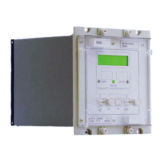
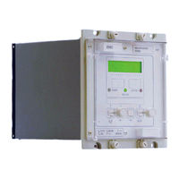
Voltage Regulating Control
Brand:
GE
| Category:
Relays
| Size: 1.98 MB
Table of Contents
Table of Contents
3
Control
4
1 Introduction
11
Using the Manual
11
Models Available
12
2 Handling and Installation
13
General Considerations
13
Receipt of Product
13
Electrostatic Discharge (ESD)
13
Handling of Electronic Equipment
13
Mounting
14
Unpacking
14
Storage
14
3 Relay Description
15
User Interface
15
Frontplate Layout
16
LED Indications
16
Keypad
17
Liquid Crystal Display
17
Menu System
17
Default Display
17
Accessing the Menu
18
Menu Contents
18
Menu Columns
19
System Data
19
Status
22
Measure
22
Logic 1
23
Control 1
23
Control 2
24
Logic 2
25
Input Masks
26
Relay Masks
26
Changing Text and Settings
27
Quick Guide to Menu Controls
27
To Enter Setting Mode
28
To Escape from the Setting Mode
28
To Accept the New Setting
28
Password Protection
29
Entering Passwords
29
Changing Passwords
29
Restoration of Password Protection
30
Entering Text
30
Changing Function Links
30
Changing Setting Values
30
Setting Communication Address
30
Setting Input Masks
31
Setting Output Masks
31
Resetting Values
31
Resetting CONTROL LED Indication
31
External Connections
31
Auxiliary Supply
32
Logic Control Inputs
33
Analogue Inputs
34
Output Relays
34
Setting the Relay with a PC or Laptop
34
Alarm Flags
35
4 Application of Control Functions
36
Configuring the Relay
36
Changing the Configuration of the Relay
36
System Data (Sd)
36
Logic Links (LOG)
37
Control Links (CTL)
38
Default Output Relays
38
Setting Group Selection
38
Applications
39
Introduction
39
Basic Requirements
39
Operating Time Delay
39
Initial Delay (Tinit)
40
Definite/Inverse Time Characteristics
40
Intertap Delay
41
Tap Pulse Duration (Tpulse)
41
Operating Sequences
41
Method 1
41
Method
42
Line Drop Compensation
42
Auto, Manual and Remote Operation Modes
43
Remote Change of Operating Mode
44
Manual Change of Operating Mode Via Logic Input
44
Paralleled Transformers
44
Master-Follower Schemes
45
Instability of Individually Controlled Parallel Transformers
46
Runaway
46
Effect of Circulating Current on LDC
47
Negative Reactance Compounding
49
Circulating Current Control
52
Independent/Parallel Control
53
Circulating Current Control with LDC
54
Supervision Functions of a VRR
60
Runaway Protection
60
Undervoltage Detection (V<)
60
Undervoltage Blocking (V<<)
61
Overvoltage Detection (V>)
61
Overcurrent Detection
61
L >)
61
Undercurrent Detection
61
Circulating Current Detection (IC>)
61
Reverse Current Detection (I Rev)
61
Tap Position Indication
61
Tap Changer Maintenance
65
Tap Change Operations Counter
65
Frequent Operations Monitor
65
Tap Changer Failure Detection
66
Load Shedding/Boosting
66
5 Relay Settings
67
Setting Voltage (Vs)
68
Deadband (Dvs)
68
Initial Time Delay Setting (Tinit)
68
Inter-Tap Delay (Tinter)
68
Tap Pulse Duration (Tpulse)
69
Line Drop Compensation (Vr and Vxl)
69
Circulating Current Compensation (VC)
69
Load Shedding/Boosting
70
Undervoltage Detector (V<)
70
Overvoltage Detector (V>)
70
Under/Over Voltage Detector Alarm Delay Timer (Tv
)
70
Undervoltage Blocking (V<<)
70
Circulating Current Detector (IC>)
70
Overcurrent Detector (IL>)
70
Undercurrent Detector (IL<)
70
Total Number of Tap Change (Totalops)
70
Total Taps Available (Tpavail)
71
Tap Fail Time Delay (Tfail)
71
Frequent Operations (Ops/Tp>)(Tp)
71
Power Factor
71
Tap Change Indication Time (Ttap Change)
71
Setting Group Selection
71
Remote Change of Setting Group
71
Manual Change of Setting Group
71
Controlled Change of Setting Group
72
Initial Factory Settings
72
System Data Settings
72
Link Settings
72
Initial Control Settings
72
Initial Logic Settings
73
Preferred Use of Logic Inputs
73
Preferred Use of Output Relays
73
6 Measurement, Records and Alarms
75
Measurement
75
Currents
75
Voltages
75
Frequency
75
Power Factor
75
Tap Position
76
Tap Changer Operations Counter
76
Frequent Operations Monitor
76
Time Remaining to Next Tap
76
Event Records
76
Triggering Event Records
77
Time Tagging of Event Records
77
Accessing and Resetting Event Records
77
Recorded Times
77
Alarm Records
77
Watchdog
77
Alarm Indication
78
Blocked Indication
78
Functional Alarms
78
Raise/Lower Volts Indication
78
Undervoltage Blocking (V<<)
78
Undervoltage Detection (V<)
78
Overvoltage Detection (V>)
79
Circulating Current Detection (IC>)
79
Overcurrent Detection (IL>)
79
Undercurrent Detection (IL<)
79
Reverse Current Blocking (Irev)
79
Run-Away
79
Tap Position Indication
80
Tap Change Operations Counter
80
Frequent Operations Monitor
80
Tap Changer Failure Mechanism
80
7 Control Functions and Serial Communications
81
Courier Language Protocol
81
K-Bus
81
K-Bus Transmission Layer
81
K-Bus Connections
82
Ancillary Equipment
83
Software Support
83
Courier Access
83
Pas&T
83
Couriercom
83
PC Requirements
84
Modem Requirements
84
Data for System Integration
85
Relay Address
85
Measured Values
85
Status Word
85
Plant Status Word
85
Control Status Word
86
Logic Input Status Word
86
Output Relay Status Word
86
Alarm Indications
86
Event Records
86
Notes on Recorded Times
86
Setting Control
87
Remote Setting Change
87
Remote Control of Setting Group
87
Loadshedding/Boosting Control
87
Remote Control of Loadshedding/Boosting
87
Local Control of Loadshedding/Boosting
88
8 Technical Data
89
Auxiliary Voltage
90
Definite Time Delay
91
Directional
92
Opto-Isolated Inputs
93
Current Transformer Requirements
94
Mechanical Environment
95
Vibration IEC 60255-21-1:1988
95
Shock and Bump IEC 60255-21 2:1988
95
Seismic IEC 60255-21-3:1993
95
Mechanical Durability
95
Conducted Immunity ENV50141:1993
95
Model Numbers
96
Frequency Response
96
Commissioning Preliminaries
98
Quick Guide to Local Menu Control
98
Terminal Allocation
98
Electrostatic Discharge (ESD)
98
Inspection
98
Earthing
98
Main Current Transformers
98
Commissioning, Problem Solving and Maintenance
98
Test Block
99
Insulation
99
Commissioning Test Notes
99
Equipment Required
99
Auxiliary Supply Tests
100
Auxiliary Supply
100
Energisation from Auxiliary Voltage Supply
100
Field Voltage
100
Settings
100
Selective Logic Functions to be Tested/Measurement Checks
101
Current Measurement
101
Measurement Checks
101
Selective Logic Functions to be Tested
101
Voltage Measurement
101
Control Functions
102
Load Shedding/Boosting
102
Regulated Voltage Setting V
102
And Dead Band Setting DV
102
Regulated Voltage Setting V S and Dead Band DV S
102
Definite Time Delay
103
Initial Time Delay
103
Integrated Timer
103
Inverse Time Delay
104
Inter-Tap Delay
105
Line Drop Compensation
105
Resistive Load Current Compensation (Vr)
105
Reactive Load Current Compensation (VX)
106
Circulating Current Compensation (VC)
107
Negative Compensation
107
Positive Compensation
107
Negative Reactance Control (Alternative Method to Circulating Current Compensation)
108
Overvoltage Detector (V>)
109
Over Voltage Detector (V>)
109
Supervision and Monitoring
109
Undervoltage Detector (V<)
109
Under Voltage Detector (V<)
109
Overcurrent Detector (IL)
110
Load Current Detector
110
Circulating Current Detector (I C )
111
Circulating Current Detector ( I C )
111
Undervoltage Blocking (V<<)
111
Under Voltage Blocking (V<<)
111
Runaway Protection
112
Load Check
114
Control Links
115
Logic Links
115
Password Lost or Not Accepted
115
Problem Solving
115
Software Link Settings
115
System Links
115
Alarms
116
Second Setting Group Not Displayed or Working
116
Setting Error Alarm
116
Software Links Cannot be Changed
116
Unconfigured or Uncalibrated Alarm
116
Watchdog Alarm
116
Communications
117
Measured Values Do Not Change
117
No Fourier" Alarm
117
No Samples" Alarm
117
No Service" Alarm
117
Problems with Event Records
117
Records
117
Maintenance
118
Measurement Accuracy
118
No Response to Remote Control Commands
118
Output Relays Remain Picked-Up
118
Relay no Longer Responding
118
Additional Tests
119
Alarms
119
Earthing
119
Local Testing
119
Main Current Transformers
119
Measurement Accuracy
119
Preliminary Checks
119
Remote Testing
119
Method of Repair
120
Replacing a Pcb
120
Replacing Output Relays and Opto-Isolators
120
Recalibration
121
Replacing the Back Plane
121
Replacing the Power Supply Board
121
Related Products
GE KTC-CBH24
GE KTC-117V3, KTC-117V9
GE KTC-117V9
GE K-3383-EB PALARRE
GE KTD-405-2D
GE Interlogix KTC-240CCE
GE KL700A
GE KL735A
GE Kilsen KFP-CF2
GE KL710
GE Categories
Refrigerator
Ranges
Microwave Oven
Air Conditioner
Dishwasher
More GE Manuals