GE 469 Communications Manual
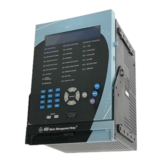
Motor management relay
Hide thumbs
Also See for 469:
- Instruction manual (348 pages) ,
- Manual (307 pages) ,
- Instruction manual (244 pages)
Table of Contents
GE
Grid Solutions
Software revision: 5.2x
GE part number: 1601-0152-AD
GE publication code: GEK-106491M
GE Grid Solutions
650 Markland Street
Markham, Ontario
Canada L6C 0M1
Tel: +1 905 927 7070 Fax: +1 905 927 5098
Internet:
http://www.gegridsolutions.com
*1601-0152-AD*
469 Motor Management Relay
Communications Guide
Table of Contents

Related Manuals for GE 469


Summary of Contents for GE 469
- Page 1 Grid Solutions 469 Motor Management Relay Communications Guide Software revision: 5.2x GE part number: 1601-0152-AD GE publication code: GEK-106491M GE Grid Solutions 650 Markland Street Markham, Ontario Canada L6C 0M1 Tel: +1 905 927 7070 Fax: +1 905 927 5098 Internet: http://www.gegridsolutions.com...
- Page 2 The contents of this manual are the property of GE Multilin Inc. This documentation is furnished on license and may not be reproduced in whole or in part without the permission of GE Multilin Inc. The content of this manual is for informational use only and is subject to change without notice.
-
Page 3: Table Of Contents
469 Memory Map ............................19 Format Codes............................... 109 DEVICENET Overview................................. 124 PROTOCOL Poll Data................................124 Change of State (COS) ..........................124 DeviceNet Objects............................125 469 Specific Objects..........................131 DeviceNet Data Formats ........................140 469 MOTOR MANAGEMENT RELAY – COMMUNICATIONS GUIDE TOC-2... - Page 4 TOC-2 469 MOTOR MANAGEMENT RELAY – COMMUNICATIONS GUIDE...
-
Page 5: Electrical Interface
Polarity is important in RS485 communications. Each ‘+’ terminal of every 469 must be connected together for the system to operate. See Chapter 2 of the 469 manual for details on correct serial port wiring. -
Page 6: Data Frame Format And Data Rate
Data Frame Format and Data Rate One data frame of an asynchronous transmission to or from an 469 is default to 1 start bit, 8 data bits, and 1 stop bit. This produces a 10 bit data frame. This is important for transmission through modems at high bit rates (11-bit data frames are not supported by Hayes modems at bit rates of greater than 300 bps). -
Page 7: Crc-16 Algorithm
CRC, when divided by the same polynomial at the receiver will give a zero remainder if no transmission errors have occurred. If an 469 Modbus slave device receives a transmission in which an error is indicated by the CRC-16 calculation, the slave device will not respond to the transmission. A CRC-... -
Page 8: Timing
(i.e. all slaves start listening for a new transmission from the master). Thus at 9600 baud a delay of greater than 3.5 × 1 / 9600 × 10 = 3.65 ms will cause the communication link to be reset. 469 MOTOR MANAGEMENT RELAY – COMMUNICATIONS GUIDE... -
Page 9: Supported Functions
Modbus implementation: Read Coil and Input Status 469 Implementation: Read Relay Coil and Digital Input Status For the 469 implementation of Modbus, these commands can be used to read Relay Coil Status or Digital Input Status. MESSAGE FORMAT AND EXAMPLE, FUNCTION 01:... - Page 10 53 93 computed CRC error code If a Starting Relay Coil (Starting Digital Input) of “0” is entered, the 469 will default it to “1”. If Note the Number of Relays (Number of Digital Inputs) requested exceeds the number of relays available, the user is prompted with an message.
-
Page 11: Read Setpoints And Actual Values
Modbus implementation: Read Input and Holding Registers 469 Implementation: Read Setpoints and Actual Values For the 469 implementation of Modbus, these commands can be used to read any setpoint (“holding registers”) or actual value (“input registers”). Holding and input registers are 16 bit (two byte) values transmitted high order byte first. -
Page 12: Execute Operation
Modbus Implementation: Preset Single Register 469 Implementation: Store Single Setpoint This command allows the master to store a single setpoint into the memory of an 469. The slave response to this function code is to echo the entire master transmission. -
Page 13: Read Device Status
3 AUXILIARY relay operated = 1 Stopped = 1 4 ALARM relay operated = 1 Running = 1 If status is neither stopped or running, the motor is starting or has been tripped. 469 MOTOR MANAGEMENT RELAY – COMMUNICATIONS GUIDE... -
Page 14: Loopback Test
CRC error code Loopback Test Modbus Implementation: Loopback Test 469 Implementation: Loopback Test This function is used to test the integrity of the communication link. The 469 will echo the request. MESSAGE FORMAT AND EXAMPLE: Loopback test from slave 11. -
Page 15: Performing Commands
MESSAGE FORMAT AND EXAMPLE: Request slave 11 to store the value 01F4 to setpoint address 1180 and the value 01DE to setpoint address 1181. After the transmission in this example is complete, 469 slave 11 will have the following Setpoints information stored:... -
Page 16: Error Responses
Error Responses When an 469 detects an error other than a CRC error, a response will be sent to the master. The MSbit of the Function Code byte will be set to 1 (i.e. the function code sent from the slave will be equal to the function code sent from the master plus 128). -
Page 17: Memory Map Information
Modbus Memory Map Memory Map Information The data stored in the 469 is grouped as setpoints and actual values. Setpoints can be read and written by a master computer. Actual Values are read only. All Setpoints and actual values are stored as two-byte values. That is, each register address is the address of a two- byte value. - Page 18 The 469 provides default assignments for user map addresses #1 to #55, as shown below. The User can change the user assigned addresses as per their requirement. To return to these default assignments, use Enervista 469 Setup to set Modbus User Map – User Map – Default.
-
Page 19: Event Recorder
Waveform Capture The 469 stores a number of cycles of A/D samples each time a trip occurs in a trace buffer. The trace buffer is partitioned according to the S1 PREFERENCES TRACE MEMORY BUFFERS setpoint. - Page 20 60 Hz or set to Variable. There are 600 samples per second when the nominal system frequency has been set to 50 Hz. Sample rate may vary within 5% when 469 is tracking the frequency of the input voltage. The actual sample rate for a trace is 12 x Trace Memory Sampling Frequency, modbus address 30F9.
- Page 21 Table 3: SR469 Internal Units per Channel External Scale factor Channel Internal Nominal Modbus Input wiring number units scale Unit or SF register current voltage Phase A current 1 x CT CT primary /500 1180 469 MOTOR MANAGEMENT RELAY – COMMUNICATIONS GUIDE...
- Page 22 Let A represent Value in waveform Ground CT Type Actual Scale factor capture trace data Multilin. Channel Primary = A / B register current Current Modbus register 3100 to 36FF 1182 has value 3. A/B=0.002 469 MOTOR MANAGEMENT RELAY – COMMUNICATIONS GUIDE...
-
Page 23: Memory Map
COMMUNICATIONS GUIDE MODBUS MEMORY MAP 469 Memory Map The 469 memory map is shown in the following table. Table 7: 469 MEMORY MAP (Sheet 1 of 90) ADDR STEP FORMAT GROUP DESCRIPTION MIN. MAX. UNITS DEFAULT (HEX) VALUE CODE PRODUCT ID (Addresses 0000 to 007F) - Page 24 MODBUS MEMORY MAP COMMUNICATIONS GUIDE Table 7: 469 MEMORY MAP (Sheet 2 of 90) ADDR STEP FORMAT GROUP DESCRIPTION MIN. MAX. UNITS DEFAULT (HEX) VALUE CODE 010C User map value #13 010D User map value #14 010E User map value #15...
- Page 25 COMMUNICATIONS GUIDE MODBUS MEMORY MAP Table 7: 469 MEMORY MAP (Sheet 3 of 90) ADDR STEP FORMAT GROUP DESCRIPTION MIN. MAX. UNITS DEFAULT (HEX) VALUE CODE 0136 User map value #55 0137 User map value #56 0138 User map value #57...
- Page 26 MODBUS MEMORY MAP COMMUNICATIONS GUIDE Table 7: 469 MEMORY MAP (Sheet 4 of 90) ADDR STEP FORMAT GROUP DESCRIPTION MIN. MAX. UNITS DEFAULT (HEX) VALUE CODE 0160 User map value #97 0161 User map value #98 0162 User map value #99...
- Page 27 COMMUNICATIONS GUIDE MODBUS MEMORY MAP Table 7: 469 MEMORY MAP (Sheet 5 of 90) ADDR STEP FORMAT GROUP DESCRIPTION MIN. MAX. UNITS DEFAULT (HEX) VALUE CODE 018A User map address #11 3FFF 018B User map address #12 3FFF 018C User map address #13...
- Page 28 MODBUS MEMORY MAP COMMUNICATIONS GUIDE Table 7: 469 MEMORY MAP (Sheet 6 of 90) ADDR STEP FORMAT GROUP DESCRIPTION MIN. MAX. UNITS DEFAULT (HEX) VALUE CODE 01B4 User map address #53 3FFF 01B5 User map address #54 3FFF 01B6 User map address #55...
- Page 29 COMMUNICATIONS GUIDE MODBUS MEMORY MAP Table 7: 469 MEMORY MAP (Sheet 7 of 90) ADDR STEP FORMAT GROUP DESCRIPTION MIN. MAX. UNITS DEFAULT (HEX) VALUE CODE 01DE User map address #95 3FFF 01DF User map address #96 3FFF 01E0 User map address #97...
- Page 30 MODBUS MEMORY MAP COMMUNICATIONS GUIDE Table 7: 469 MEMORY MAP (Sheet 8 of 90) ADDR STEP FORMAT GROUP DESCRIPTION MIN. MAX. UNITS DEFAULT (HEX) VALUE CODE 020F Reserved SYSTEM 0210 General status 65535 F140 STATUS 0211 Output relay status F141...
- Page 31 COMMUNICATIONS GUIDE MODBUS MEMORY MAP Table 7: 469 MEMORY MAP (Sheet 9 of 90) ADDR STEP FORMAT GROUP DESCRIPTION MIN. MAX. UNITS DEFAULT (HEX) VALUE CODE 0249 Analog input #1 pre-trip power –50000 50000 024B Analog input #2 pre-trip power –50000...
- Page 32 MODBUS MEMORY MAP COMMUNICATIONS GUIDE Table 7: 469 MEMORY MAP (Sheet 10 of 90) ADDR STEP FORMAT GROUP DESCRIPTION MIN. MAX. UNITS DEFAULT (HEX) VALUE CODE 027E RTD #12 alarm status F123 027F Open RTD sensor alarm status F123 0280...
- Page 33 COMMUNICATIONS GUIDE MODBUS MEMORY MAP Table 7: 469 MEMORY MAP (Sheet 11 of 90) ADDR STEP FORMAT GROUP DESCRIPTION MIN. MAX. UNITS DEFAULT (HEX) VALUE CODE 02B2 Starts/hour block lockout time minutes 02B3 Time between starts lockout time minutes 02B4...
- Page 34 MODBUS MEMORY MAP COMMUNICATIONS GUIDE Table 7: 469 MEMORY MAP (Sheet 12 of 90) ADDR STEP FORMAT GROUP DESCRIPTION MIN. MAX. UNITS DEFAULT (HEX) VALUE CODE TEMPER- 0320 Hottest stator RTD –50 °C ATURE 0321 RTD #1 temperature –50 °C...
- Page 35 COMMUNICATIONS GUIDE MODBUS MEMORY MAP Table 7: 469 MEMORY MAP (Sheet 13 of 90) ADDR STEP FORMAT GROUP DESCRIPTION MIN. MAX. UNITS DEFAULT (HEX) VALUE CODE 0349 Reserved 034A Reserved 035F Reserved SPEED 0360 Tachometer RPM 7200 0361 Reserved 0362...
- Page 36 MODBUS MEMORY MAP COMMUNICATIONS GUIDE Table 7: 469 MEMORY MAP (Sheet 14 of 90) ADDR STEP FORMAT GROUP DESCRIPTION MIN. MAX. UNITS DEFAULT (HEX) VALUE CODE 03BC Reserved 03BD Reserved 03BE Reserved 03BF Reserved MOTOR 03C0 Learned acceleration time 2000...
- Page 37 COMMUNICATIONS GUIDE MODBUS MEMORY MAP Table 7: 469 MEMORY MAP (Sheet 15 of 90) ADDR STEP FORMAT GROUP DESCRIPTION MIN. MAX. UNITS DEFAULT (HEX) VALUE CODE 03F6 RTD #7 maximum temperature (in °F) –58 °F 03F7 RTD #8 maximum temperature (in °F) –58...
- Page 38 MODBUS MEMORY MAP COMMUNICATIONS GUIDE Table 7: 469 MEMORY MAP (Sheet 16 of 90) ADDR STEP FORMAT GROUP DESCRIPTION MIN. MAX. UNITS DEFAULT (HEX) VALUE CODE 043C Stator RTD trips 50000 043D Bearing RTD trips 50000 043E Other RTD trips...
- Page 39 COMMUNICATIONS GUIDE MODBUS MEMORY MAP Table 7: 469 MEMORY MAP (Sheet 17 of 90) ADDR STEP FORMAT GROUP DESCRIPTION MIN. MAX. UNITS DEFAULT (HEX) VALUE CODE 469 MODEL INFORMATION 04C0 Order code 65535 F136 A300000 04C1 Relay serial number (read only)
- Page 40 MODBUS MEMORY MAP COMMUNICATIONS GUIDE Table 7: 469 MEMORY MAP (Sheet 18 of 90) ADDR STEP FORMAT GROUP DESCRIPTION MIN. MAX. UNITS DEFAULT (HEX) VALUE CODE 064B Reserved 064C Ethernet status F152 064D Reserved 064E Reserved 0FFF Reserved SETPOINTS (Addresses 1000 to 1FFF)
- Page 41 COMMUNICATIONS GUIDE MODBUS MEMORY MAP Table 7: 469 MEMORY MAP (Sheet 19 of 90) ADDR STEP FORMAT GROUP DESCRIPTION MIN. MAX. UNITS DEFAULT (HEX) VALUE CODE 102F Reserved REAL TIME 1030 Date CLOCK 1032 Time 1034 Reserved 1035 Reserved 103F...
- Page 42 MODBUS MEMORY MAP COMMUNICATIONS GUIDE Table 7: 469 MEMORY MAP (Sheet 20 of 90) ADDR STEP FORMAT GROUP DESCRIPTION MIN. MAX. UNITS DEFAULT (HEX) VALUE CODE 1086 Scratchpad message 2 characters 13 and 14 32 ‘ ’ 1087 Scratchpad message 2 characters 15 and 16 32 ‘...
- Page 43 COMMUNICATIONS GUIDE MODBUS MEMORY MAP Table 7: 469 MEMORY MAP (Sheet 21 of 90) ADDR STEP FORMAT GROUP DESCRIPTION MIN. MAX. UNITS DEFAULT (HEX) VALUE CODE 10C0 Scratchpad message 4 characters 1 and 2 ‘Te’ 10C1 Scratchpad message 4 characters 3 and 4 ‘xt’...
- Page 44 MODBUS MEMORY MAP COMMUNICATIONS GUIDE Table 7: 469 MEMORY MAP (Sheet 22 of 90) ADDR STEP FORMAT GROUP DESCRIPTION MIN. MAX. UNITS DEFAULT (HEX) VALUE CODE 10F2 Scratchpad message 5 characters 37 and 38 32 ‘ ’ 10F3 Scratchpad message 5 characters 39 and 40 32 ‘...
- Page 45 COMMUNICATIONS GUIDE MODBUS MEMORY MAP Table 7: 469 MEMORY MAP (Sheet 23 of 90) ADDR STEP FORMAT GROUP DESCRIPTION MIN. MAX. UNITS DEFAULT (HEX) VALUE CODE 11A4 Reserved 11A5 Reserved 11BF Reserved POWER 11C0 Nominal system frequency F107 SYSTEM 11C1...
- Page 46 MODBUS MEMORY MAP COMMUNICATIONS GUIDE Table 7: 469 MEMORY MAP (Sheet 24 of 90) ADDR STEP FORMAT GROUP DESCRIPTION MIN. MAX. UNITS DEFAULT (HEX) VALUE CODE REMOTE 125A Remote alarm name characters 1 and 2 65535 ‘Re’ ALARM 125B Remote alarm name characters 3 and 4 65535 ‘mo’...
- Page 47 COMMUNICATIONS GUIDE MODBUS MEMORY MAP Table 7: 469 MEMORY MAP (Sheet 25 of 90) ADDR STEP FORMAT GROUP DESCRIPTION MIN. MAX. UNITS DEFAULT (HEX) VALUE CODE 12AF Reserved PRESSURE SWITCH 12B0 Block pressure switch alarm from start 5000 ALARM 12B1...
- Page 48 MODBUS MEMORY MAP COMMUNICATIONS GUIDE Table 7: 469 MEMORY MAP (Sheet 26 of 90) ADDR STEP FORMAT GROUP DESCRIPTION MIN. MAX. UNITS DEFAULT (HEX) VALUE CODE 12FA Digital counter alarm relays F113 10000000 12FB Digital counter alarm level 12FD Digital counter alarm pickup...
- Page 49 COMMUNICATIONS GUIDE MODBUS MEMORY MAP Table 7: 469 MEMORY MAP (Sheet 27 of 90) ADDR STEP FORMAT GROUP DESCRIPTION MIN. MAX. UNITS DEFAULT (HEX) VALUE CODE GENERAL 1366 General switch B name, characters 1 and 2 65535 ‘Ge’ SWITCH B...
- Page 50 MODBUS MEMORY MAP COMMUNICATIONS GUIDE Table 7: 469 MEMORY MAP (Sheet 28 of 90) ADDR STEP FORMAT GROUP DESCRIPTION MIN. MAX. UNITS DEFAULT (HEX) VALUE CODE 13C9 General switch D name, characters 7 and 8 65535 ‘l ’ 13CA General switch D name, characters 9 and 10 65535 ‘Sw’...
- Page 51 COMMUNICATIONS GUIDE MODBUS MEMORY MAP Table 7: 469 MEMORY MAP (Sheet 29 of 90) ADDR STEP FORMAT GROUP DESCRIPTION MIN. MAX. UNITS DEFAULT (HEX) VALUE CODE 1584 Cool time constant stopped 1000 minutes 1585 Hot/cold safe stall ratio 1586 RTD biasing...
- Page 52 MODBUS MEMORY MAP COMMUNICATIONS GUIDE Table 7: 469 MEMORY MAP (Sheet 30 of 90) ADDR STEP FORMAT GROUP DESCRIPTION MIN. MAX. UNITS DEFAULT (HEX) VALUE CODE 15E4 Time to trip at 8.00 x FLA 999999 15E6 Time to trip at 10.0 x FLA...
- Page 53 COMMUNICATIONS GUIDE MODBUS MEMORY MAP Table 7: 469 MEMORY MAP (Sheet 31 of 90) ADDR STEP FORMAT GROUP DESCRIPTION MIN. MAX. UNITS DEFAULT (HEX) VALUE CODE × FLA 1662 Mechanical jam pickup 1663 Mechanical jam delay 1664 Reserved 1665 Reserved...
- Page 54 MODBUS MEMORY MAP COMMUNICATIONS GUIDE Table 7: 469 MEMORY MAP (Sheet 32 of 90) ADDR STEP FORMAT GROUP DESCRIPTION MIN. MAX. UNITS DEFAULT (HEX) VALUE CODE 16A6 Ground fault alarm events F103 16A7 Ground fault trip F115 16A8 Ground fault trip relays...
- Page 55 COMMUNICATIONS GUIDE MODBUS MEMORY MAP Table 7: 469 MEMORY MAP (Sheet 33 of 90) ADDR STEP FORMAT GROUP DESCRIPTION MIN. MAX. UNITS DEFAULT (HEX) VALUE CODE 16F4 Reserved 16FF Reserved RESTART 1700 Restart block F103 BLOCK 1701 Restart block time...
- Page 56 MODBUS MEMORY MAP COMMUNICATIONS GUIDE Table 7: 469 MEMORY MAP (Sheet 34 of 90) ADDR STEP FORMAT GROUP DESCRIPTION MIN. MAX. UNITS DEFAULT (HEX) VALUE CODE 17B6 RTD #2 trip voting F122 17B7 RTD #2 trip relays F111 17B8 RTD #2 trip temperature °C...
- Page 57 COMMUNICATIONS GUIDE MODBUS MEMORY MAP Table 7: 469 MEMORY MAP (Sheet 35 of 90) ADDR STEP FORMAT GROUP DESCRIPTION MIN. MAX. UNITS DEFAULT (HEX) VALUE CODE 17FA 3rd and 4th characters of RTD #4 name 65535 ‘ ’ 17FB 5th and 6th characters of RTD #4 name 65535 ‘...
- Page 58 MODBUS MEMORY MAP COMMUNICATIONS GUIDE Table 7: 469 MEMORY MAP (Sheet 36 of 90) ADDR STEP FORMAT GROUP DESCRIPTION MIN. MAX. UNITS DEFAULT (HEX) VALUE CODE 183E Reserved 184D Reserved 184E RTD #6 alarm temperature (in Fahrenheit) °F 184F RTD #6 trip temperature (in Fahrenheit) °F...
- Page 59 COMMUNICATIONS GUIDE MODBUS MEMORY MAP Table 7: 469 MEMORY MAP (Sheet 37 of 90) ADDR STEP FORMAT GROUP DESCRIPTION MIN. MAX. UNITS DEFAULT (HEX) VALUE CODE 188F RTD #8 trip temperature (in Fahrenheit) °F RTD #9 1890 RTD #9 application...
- Page 60 MODBUS MEMORY MAP COMMUNICATIONS GUIDE Table 7: 469 MEMORY MAP (Sheet 38 of 90) ADDR STEP FORMAT GROUP DESCRIPTION MIN. MAX. UNITS DEFAULT (HEX) VALUE CODE 18D3 RTD #11 alarm temperature °C 18D4 RTD #11 alarm events F103 18D5 RTD #11 trip...
- Page 61 COMMUNICATIONS GUIDE MODBUS MEMORY MAP Table 7: 469 MEMORY MAP (Sheet 39 of 90) ADDR STEP FORMAT GROUP DESCRIPTION MIN. MAX. UNITS DEFAULT (HEX) VALUE CODE RTD SHORT/ 1920 RTD Short / Low Temp Alarm F115 LOW TEMP 1921 RTD Short / Low Temp Alarm Relays...
- Page 62 MODBUS MEMORY MAP COMMUNICATIONS GUIDE Table 7: 469 MEMORY MAP (Sheet 40 of 90) ADDR STEP FORMAT GROUP DESCRIPTION MIN. MAX. UNITS DEFAULT (HEX) VALUE CODE 1952 RTD #9 high alarm level °C 1953 Reserved 1954 RTD #10 high Alarm...
- Page 63 COMMUNICATIONS GUIDE MODBUS MEMORY MAP Table 7: 469 MEMORY MAP (Sheet 41 of 90) ADDR STEP FORMAT GROUP DESCRIPTION MIN. MAX. UNITS DEFAULT (HEX) VALUE CODE 198A Reserved 199F Reserved PHASE 19A0 Voltage phase reversal trip F115 REVERSAL 19A1 Voltage phase reversal trip relays...
- Page 64 MODBUS MEMORY MAP COMMUNICATIONS GUIDE Table 7: 469 MEMORY MAP (Sheet 42 of 90) ADDR STEP FORMAT GROUP DESCRIPTION MIN. MAX. UNITS DEFAULT (HEX) VALUE CODE REACTIVE 19F0 Block kvar element from start 5000 POWER 19F1 Reactive power alarm F115...
- Page 65 COMMUNICATIONS GUIDE MODBUS MEMORY MAP Table 7: 469 MEMORY MAP (Sheet 43 of 90) ADDR STEP FORMAT GROUP DESCRIPTION MIN. MAX. UNITS DEFAULT (HEX) VALUE CODE 1A2B Reserved … … 1A2F Reserved TORQUE 1A30 Torque metering F126 SETUP 1A31 Stator resistance 50000 mΩ...
- Page 66 MODBUS MEMORY MAP COMMUNICATIONS GUIDE Table 7: 469 MEMORY MAP (Sheet 44 of 90) ADDR STEP FORMAT GROUP DESCRIPTION MIN. MAX. UNITS DEFAULT (HEX) VALUE CODE CURRENT 1AD0 Current demand period DEMAND 1AD1 Current demand alarm F115 1AD2 Current demand alarm relays...
- Page 67 COMMUNICATIONS GUIDE MODBUS MEMORY MAP Table 7: 469 MEMORY MAP (Sheet 45 of 90) ADDR STEP FORMAT GROUP DESCRIPTION MIN. MAX. UNITS DEFAULT (HEX) VALUE CODE 1B15 Negative kvarh pulse output interval 50000 kvarh 1B16 Running time pulse relay F144...
- Page 68 MODBUS MEMORY MAP COMMUNICATIONS GUIDE Table 7: 469 MEMORY MAP (Sheet 46 of 90) ADDR STEP FORMAT GROUP DESCRIPTION MIN. MAX. UNITS DEFAULT (HEX) VALUE CODE 1B5F Phase BN voltage maximum 20000 2500 1B60 Phase CN voltage minimum 20000 1900...
- Page 69 COMMUNICATIONS GUIDE MODBUS MEMORY MAP Table 7: 469 MEMORY MAP (Sheet 47 of 90) ADDR STEP FORMAT GROUP DESCRIPTION MIN. MAX. UNITS DEFAULT (HEX) VALUE CODE 1B8D Apparent power maximum 50000 1250 1B8E Thermal capacity used minimum %used 1B8F Thermal capacity used maximum...
- Page 70 MODBUS MEMORY MAP COMMUNICATIONS GUIDE Table 7: 469 MEMORY MAP (Sheet 48 of 90) ADDR STEP FORMAT GROUP DESCRIPTION MIN. MAX. UNITS DEFAULT (HEX) VALUE CODE 1BD8 Hottest ambient RTD minimum (in °F) –57 °F –57 1BD9 Hottest ambient RTD maximum (in °F) –57...
- Page 71 COMMUNICATIONS GUIDE MODBUS MEMORY MAP Table 7: 469 MEMORY MAP (Sheet 49 of 90) ADDR STEP FORMAT GROUP DESCRIPTION MIN. MAX. UNITS DEFAULT (HEX) VALUE CODE 1C0F Reserved 1C10 Analog input 1 units, characters 1 and 2 65535 ‘Un’ 1C11...
- Page 72 MODBUS MEMORY MAP COMMUNICATIONS GUIDE Table 7: 469 MEMORY MAP (Sheet 50 of 90) ADDR STEP FORMAT GROUP DESCRIPTION MIN. MAX. UNITS DEFAULT (HEX) VALUE CODE 1C5C Analog input 2 alarm pickup F130 1C5D Analog input 2 alarm delay 3000...
- Page 73 COMMUNICATIONS GUIDE MODBUS MEMORY MAP Table 7: 469 MEMORY MAP (Sheet 51 of 90) ADDR STEP FORMAT GROUP DESCRIPTION MIN. MAX. UNITS DEFAULT (HEX) VALUE CODE 1CA8 Analog input 3 name, characters 5 and 6 65535 ‘og’ 1CA8 Analog input 3 name, characters 7 and 8 65535 ‘...
- Page 74 MODBUS MEMORY MAP COMMUNICATIONS GUIDE Table 7: 469 MEMORY MAP (Sheet 52 of 90) ADDR STEP FORMAT GROUP DESCRIPTION MIN. MAX. UNITS DEFAULT (HEX) VALUE CODE SIMULATION 1D00 Simulation mode F138 MODE 1D01 Pre-fault to fault time delay 1D02 Reserved...
- Page 75 COMMUNICATIONS GUIDE MODBUS MEMORY MAP Table 7: 469 MEMORY MAP (Sheet 53 of 90) ADDR STEP FORMAT GROUP DESCRIPTION MIN. MAX. UNITS DEFAULT (HEX) VALUE CODE 1D4B Fault analog input 1 %range 1D4C Fault analog input 2 %range 1D4D Fault analog input 3...
- Page 76 MODBUS MEMORY MAP COMMUNICATIONS GUIDE Table 7: 469 MEMORY MAP (Sheet 54 of 90) ADDR STEP FORMAT GROUP DESCRIPTION MIN. MAX. UNITS DEFAULT (HEX) VALUE CODE 1E18 Speed 2 time to trip at 3.00 x FLA 999999 1E1A Speed 2 time to trip at 3.25 x FLA...
- Page 77 COMMUNICATIONS GUIDE MODBUS MEMORY MAP Table 7: 469 MEMORY MAP (Sheet 55 of 90) ADDR STEP FORMAT GROUP DESCRIPTION MIN. MAX. UNITS DEFAULT (HEX) VALUE CODE × FLA 1E98 Speed 2 undercurrent trip pickup 1E99 Speed 2 undercurrent trip delay...
- Page 78 MODBUS MEMORY MAP COMMUNICATIONS GUIDE Table 7: 469 MEMORY MAP (Sheet 56 of 90) ADDR STEP FORMAT GROUP DESCRIPTION MIN. MAX. UNITS DEFAULT (HEX) VALUE CODE ANALOG INPUT 3-4 1F20 Analog In Differential 3-4 Enable F126 DIFF. 1F21 1st & 2nd chars. of analog in diff 3-4 name 65535 ‘An’...
- Page 79 COMMUNICATIONS GUIDE MODBUS MEMORY MAP Table 7: 469 MEMORY MAP (Sheet 57 of 90) ADDR STEP FORMAT GROUP DESCRIPTION MIN. MAX. UNITS DEFAULT (HEX) VALUE CODE 3015 Event phase A differential current 5000 3016 Event phase B differential current 5000...
- Page 80 MODBUS MEMORY MAP COMMUNICATIONS GUIDE Table 7: 469 MEMORY MAP (Sheet 58 of 90) ADDR STEP FORMAT GROUP DESCRIPTION MIN. MAX. UNITS DEFAULT (HEX) VALUE CODE 30F6 Trace trigger cause F134 30F7 Number of samples per trace 1536 30F8 Number of traces taken...
- Page 81 COMMUNICATIONS GUIDE MODBUS MEMORY MAP Table 7: 469 MEMORY MAP (Sheet 59 of 90) ADDR STEP FORMAT GROUP DESCRIPTION MIN. MAX. UNITS DEFAULT (HEX) VALUE CODE 3123 Trace memory sample #36 -32767 32767 F157 3124 Trace memory sample #37 -32767...
- Page 82 MODBUS MEMORY MAP COMMUNICATIONS GUIDE Table 7: 469 MEMORY MAP (Sheet 60 of 90) ADDR STEP FORMAT GROUP DESCRIPTION MIN. MAX. UNITS DEFAULT (HEX) VALUE CODE 3153 Trace memory sample #84 -32767 32767 F157 3154 Trace memory sample #85 -32767...
- Page 83 COMMUNICATIONS GUIDE MODBUS MEMORY MAP Table 7: 469 MEMORY MAP (Sheet 61 of 90) ADDR STEP FORMAT GROUP DESCRIPTION MIN. MAX. UNITS DEFAULT (HEX) VALUE CODE 3183 Trace memory sample #132 -32767 32767 F157 3184 Trace memory sample #133 -32767...
- Page 84 MODBUS MEMORY MAP COMMUNICATIONS GUIDE Table 7: 469 MEMORY MAP (Sheet 62 of 90) ADDR STEP FORMAT GROUP DESCRIPTION MIN. MAX. UNITS DEFAULT (HEX) VALUE CODE 31B3 Trace memory sample #180 -32767 32767 F157 31B4 Trace memory sample #181 -32767...
- Page 85 COMMUNICATIONS GUIDE MODBUS MEMORY MAP Table 7: 469 MEMORY MAP (Sheet 63 of 90) ADDR STEP FORMAT GROUP DESCRIPTION MIN. MAX. UNITS DEFAULT (HEX) VALUE CODE 31E3 Trace memory sample #228 -32767 32767 F157 31E4 Trace memory sample #229 -32767...
- Page 86 MODBUS MEMORY MAP COMMUNICATIONS GUIDE Table 7: 469 MEMORY MAP (Sheet 64 of 90) ADDR STEP FORMAT GROUP DESCRIPTION MIN. MAX. UNITS DEFAULT (HEX) VALUE CODE 3213 Trace memory sample #276 -32767 32767 F157 3214 Trace memory sample #277 -32767...
- Page 87 COMMUNICATIONS GUIDE MODBUS MEMORY MAP Table 7: 469 MEMORY MAP (Sheet 65 of 90) ADDR STEP FORMAT GROUP DESCRIPTION MIN. MAX. UNITS DEFAULT (HEX) VALUE CODE 3243 Trace memory sample #324 -32767 32767 F157 3244 Trace memory sample #325 -32767...
- Page 88 MODBUS MEMORY MAP COMMUNICATIONS GUIDE Table 7: 469 MEMORY MAP (Sheet 66 of 90) ADDR STEP FORMAT GROUP DESCRIPTION MIN. MAX. UNITS DEFAULT (HEX) VALUE CODE 3273 Trace memory sample #372 -32767 32767 F157 3274 Trace memory sample #373 -32767...
- Page 89 COMMUNICATIONS GUIDE MODBUS MEMORY MAP Table 7: 469 MEMORY MAP (Sheet 67 of 90) ADDR STEP FORMAT GROUP DESCRIPTION MIN. MAX. UNITS DEFAULT (HEX) VALUE CODE 32A3 Trace memory sample #420 -32767 32767 F157 32A4 Trace memory sample #421 -32767...
- Page 90 MODBUS MEMORY MAP COMMUNICATIONS GUIDE Table 7: 469 MEMORY MAP (Sheet 68 of 90) ADDR STEP FORMAT GROUP DESCRIPTION MIN. MAX. UNITS DEFAULT (HEX) VALUE CODE 32D3 Trace memory sample #468 -32767 32767 F157 32D4 Trace memory sample #469 -32767...
- Page 91 COMMUNICATIONS GUIDE MODBUS MEMORY MAP Table 7: 469 MEMORY MAP (Sheet 69 of 90) ADDR STEP FORMAT GROUP DESCRIPTION MIN. MAX. UNITS DEFAULT (HEX) VALUE CODE 3303 Trace memory sample #516 -32767 32767 F157 3304 Trace memory sample #517 -32767...
- Page 92 MODBUS MEMORY MAP COMMUNICATIONS GUIDE Table 7: 469 MEMORY MAP (Sheet 70 of 90) ADDR STEP FORMAT GROUP DESCRIPTION MIN. MAX. UNITS DEFAULT (HEX) VALUE CODE 3333 Trace memory sample #564 -32767 32767 F157 3334 Trace memory sample #565 -32767...
- Page 93 COMMUNICATIONS GUIDE MODBUS MEMORY MAP Table 7: 469 MEMORY MAP (Sheet 71 of 90) ADDR STEP FORMAT GROUP DESCRIPTION MIN. MAX. UNITS DEFAULT (HEX) VALUE CODE 3363 Trace memory sample #612 -32767 32767 F157 3364 Trace memory sample #613 -32767...
- Page 94 MODBUS MEMORY MAP COMMUNICATIONS GUIDE Table 7: 469 MEMORY MAP (Sheet 72 of 90) ADDR STEP FORMAT GROUP DESCRIPTION MIN. MAX. UNITS DEFAULT (HEX) VALUE CODE 3393 Trace memory sample #660 -32767 32767 F157 3394 Trace memory sample #661 -32767...
- Page 95 COMMUNICATIONS GUIDE MODBUS MEMORY MAP Table 7: 469 MEMORY MAP (Sheet 73 of 90) ADDR STEP FORMAT GROUP DESCRIPTION MIN. MAX. UNITS DEFAULT (HEX) VALUE CODE 33C3 Trace memory sample #708 -32767 32767 F157 33C4 Trace memory sample #709 -32767...
- Page 96 MODBUS MEMORY MAP COMMUNICATIONS GUIDE Table 7: 469 MEMORY MAP (Sheet 74 of 90) ADDR STEP FORMAT GROUP DESCRIPTION MIN. MAX. UNITS DEFAULT (HEX) VALUE CODE 33F3 Trace memory sample #756 -32767 32767 F157 33F4 Trace memory sample #757 -32767...
- Page 97 COMMUNICATIONS GUIDE MODBUS MEMORY MAP Table 7: 469 MEMORY MAP (Sheet 75 of 90) ADDR STEP FORMAT GROUP DESCRIPTION MIN. MAX. UNITS DEFAULT (HEX) VALUE CODE 3423 Trace memory sample #804 -32767 32767 F157 3424 Trace memory sample #805 -32767...
- Page 98 MODBUS MEMORY MAP COMMUNICATIONS GUIDE Table 7: 469 MEMORY MAP (Sheet 76 of 90) ADDR STEP FORMAT GROUP DESCRIPTION MIN. MAX. UNITS DEFAULT (HEX) VALUE CODE 3453 Trace memory sample #852 -32767 32767 F157 3454 Trace memory sample #853 -32767...
- Page 99 COMMUNICATIONS GUIDE MODBUS MEMORY MAP Table 7: 469 MEMORY MAP (Sheet 77 of 90) ADDR STEP FORMAT GROUP DESCRIPTION MIN. MAX. UNITS DEFAULT (HEX) VALUE CODE 3483 Trace memory sample #900 -32767 32767 F157 3484 Trace memory sample #901 -32767...
- Page 100 MODBUS MEMORY MAP COMMUNICATIONS GUIDE Table 7: 469 MEMORY MAP (Sheet 78 of 90) ADDR STEP FORMAT GROUP DESCRIPTION MIN. MAX. UNITS DEFAULT (HEX) VALUE CODE 34B3 Trace memory sample #948 -32767 32767 F157 34B4 Trace memory sample #949 -32767...
- Page 101 COMMUNICATIONS GUIDE MODBUS MEMORY MAP Table 7: 469 MEMORY MAP (Sheet 79 of 90) ADDR STEP FORMAT GROUP DESCRIPTION MIN. MAX. UNITS DEFAULT (HEX) VALUE CODE 34E3 Trace memory sample #996 -32767 32767 F157 34E4 Trace memory sample #997 -32767...
- Page 102 MODBUS MEMORY MAP COMMUNICATIONS GUIDE Table 7: 469 MEMORY MAP (Sheet 80 of 90) ADDR STEP FORMAT GROUP DESCRIPTION MIN. MAX. UNITS DEFAULT (HEX) VALUE CODE 3513 Trace memory sample #1044 -32767 32767 F157 3514 Trace memory sample #1045 -32767...
- Page 103 COMMUNICATIONS GUIDE MODBUS MEMORY MAP Table 7: 469 MEMORY MAP (Sheet 81 of 90) ADDR STEP FORMAT GROUP DESCRIPTION MIN. MAX. UNITS DEFAULT (HEX) VALUE CODE 3543 Trace memory sample #1092 -32767 32767 F157 3544 Trace memory sample #1093 -32767...
- Page 104 MODBUS MEMORY MAP COMMUNICATIONS GUIDE Table 7: 469 MEMORY MAP (Sheet 82 of 90) ADDR STEP FORMAT GROUP DESCRIPTION MIN. MAX. UNITS DEFAULT (HEX) VALUE CODE 3573 Trace memory sample #1140 -32767 32767 F157 3574 Trace memory sample #1141 -32767...
- Page 105 COMMUNICATIONS GUIDE MODBUS MEMORY MAP Table 7: 469 MEMORY MAP (Sheet 83 of 90) ADDR STEP FORMAT GROUP DESCRIPTION MIN. MAX. UNITS DEFAULT (HEX) VALUE CODE 35A3 Trace memory sample #1188 -32767 32767 F157 35A4 Trace memory sample #1189 -32767...
- Page 106 MODBUS MEMORY MAP COMMUNICATIONS GUIDE Table 7: 469 MEMORY MAP (Sheet 84 of 90) ADDR STEP FORMAT GROUP DESCRIPTION MIN. MAX. UNITS DEFAULT (HEX) VALUE CODE 35D3 Trace memory sample #1236 -32767 32767 F157 35D4 Trace memory sample #1237 -32767...
- Page 107 COMMUNICATIONS GUIDE MODBUS MEMORY MAP Table 7: 469 MEMORY MAP (Sheet 85 of 90) ADDR STEP FORMAT GROUP DESCRIPTION MIN. MAX. UNITS DEFAULT (HEX) VALUE CODE 3603 Trace memory sample #1284 -32767 32767 F157 3604 Trace memory sample #1285 -32767...
- Page 108 MODBUS MEMORY MAP COMMUNICATIONS GUIDE Table 7: 469 MEMORY MAP (Sheet 86 of 90) ADDR STEP FORMAT GROUP DESCRIPTION MIN. MAX. UNITS DEFAULT (HEX) VALUE CODE 3633 Trace memory sample #1332 -32767 32767 F157 3634 Trace memory sample #1333 -32767...
- Page 109 COMMUNICATIONS GUIDE MODBUS MEMORY MAP Table 7: 469 MEMORY MAP (Sheet 87 of 90) ADDR STEP FORMAT GROUP DESCRIPTION MIN. MAX. UNITS DEFAULT (HEX) VALUE CODE 3663 Trace memory sample #1380 -32767 32767 F157 3664 Trace memory sample #1381 -32767...
- Page 110 MODBUS MEMORY MAP COMMUNICATIONS GUIDE Table 7: 469 MEMORY MAP (Sheet 88 of 90) ADDR STEP FORMAT GROUP DESCRIPTION MIN. MAX. UNITS DEFAULT (HEX) VALUE CODE 3693 Trace memory sample #1428 -32767 32767 F157 3694 Trace memory sample #1429 -32767...
- Page 111 COMMUNICATIONS GUIDE MODBUS MEMORY MAP Table 7: 469 MEMORY MAP (Sheet 89 of 90) ADDR STEP FORMAT GROUP DESCRIPTION MIN. MAX. UNITS DEFAULT (HEX) VALUE CODE 36C3 Trace memory sample #1476 -32767 32767 F157 36C4 Trace memory sample #1477 -32767...
- Page 112 MODBUS MEMORY MAP COMMUNICATIONS GUIDE Table 7: 469 MEMORY MAP (Sheet 90 of 90) ADDR STEP FORMAT GROUP DESCRIPTION MIN. MAX. UNITS DEFAULT (HEX) VALUE CODE 36F3 Trace memory sample #1524 -32767 32767 F157 36F4 Trace memory sample #1525 -32767...
-
Page 113: Format Codes
VALUE, 1 DECIMAL PLACE 1st 16 bits High Order Word of Long Value 2nd 16 bits Low Order Word of Long Value Example: -12345.6 stored as -123456 (i.e. 1st word: FFFE hex, 2nd word: 1DC0 hex) 469 MOTOR MANAGEMENT RELAY – COMMUNICATIONS GUIDE... - Page 114 16 bits 2 DECIMAL PLACES (Power Factor) < 0 Leading Power Factor - Negative > 0 Lagging Power Factor - Positive Example: Power Factor of 0.87 lag is used as 87 (i.e. 0057) 469 MOTOR MANAGEMENT RELAY – COMMUNICATIONS GUIDE...
- Page 115 On / Yes Unsigned GROUND CT TYPE 16 bit integer None F104 1 A Secondary 5 A Secondary 50/0.025 CT Unsigned DIFFERENTIAL CT TYPE 16 bit integer None F105 1 A Secondary 5 A Secondary 469 MOTOR MANAGEMENT RELAY – COMMUNICATIONS GUIDE...
- Page 116 Capture Trace Simulate Pre-Fault Simulate Fault Simulate Pre-Fault...Fault Unsigned TRIP RELAYS 16 bit integer Trip F111 Trip & Aux2 Trip & Aux2 & Aux3 Trip & Aux3 Unsigned NOT DEFINED 16 bit integer F112 469 MOTOR MANAGEMENT RELAY – COMMUNICATIONS GUIDE...
- Page 117 Aux3 Unsigned BACKUP RELAYS 16 bit integer Aux2 F119 Aux2 & Aux3 Aux3 Unsigned RTD TYPE 16 bit integer 100 Ohm Platinum F120 120 Ohm Nickel 100 Ohm Nickel 10 Ohm Copper 469 MOTOR MANAGEMENT RELAY – COMMUNICATIONS GUIDE...
- Page 118 Timing Out Active Latched Unsigned PHASE ROTATION AT MOTOR 16 bit integer TERMINALS F124 Unsigned STARTER TYPE 16 bit integer F125 Breaker Contactor Unsigned DISABLED / ENABLED SELECTION 16 bit F126 Disabled Enabled 469 MOTOR MANAGEMENT RELAY – COMMUNICATIONS GUIDE...
- Page 119 Relay Lockout Time Current Demand kvar Demand kW Demand kVA Demand Motor Load Analog Input 1 Analog Input 2 Analog Input 3 Analog Input 4 Tachometer MWhrs Analog In Diff 1-2 Analog In Diff 3-4 469 MOTOR MANAGEMENT RELAY – COMMUNICATIONS GUIDE...
- Page 120 INPUT SWITCH STATUS 16 bit integer F131 Open Shorted Unsigned TRIP COIL SUPERVISION STATUS 16 bit integer F132 No Coil Coil Unsigned MOTOR STATUS 16 bit integer Stopped Starting F133 Running Overloaded Tripped 469 MOTOR MANAGEMENT RELAY – COMMUNICATIONS GUIDE...
- Page 121 RTD 3 Trip RTD 4 Trip RTD 5 Trip RTD 6 Trip RTD 7 Trip RTD 8 Trip RTD 9 Trip RTD 10 Trip RTD 11 Trip RTD 12 Trip Undervoltage Trip Overvoltage Trip 469 MOTOR MANAGEMENT RELAY – COMMUNICATIONS GUIDE...
- Page 122 RTD 4 Alarm RTD 5 Alarm RTD 6 Alarm RTD 7 Alarm RTD 8 Alarm RTD 9 Alarm RTD 10 Alarm RTD 11 Alarm RTD 12 Alarm Open RTD Alarm Short/Low RTD Alarm 469 MOTOR MANAGEMENT RELAY – COMMUNICATIONS GUIDE...
- Page 123 RTD 2 High Alarm RTD 3 High Alarm RTD 4 High Alarm RTD 5 High Alarm RTD 6 High Alarm RTD 7 High Alarm RTD 8 High Alarm RTD 9 High Alarm RTD 10 High Alarm 469 MOTOR MANAGEMENT RELAY – COMMUNICATIONS GUIDE...
- Page 124 Simulate Pre-Fault Simulate Fault Pre-Fault to Fault Unsigned FORCE OPERATION OF RELAYS 16 bit integer Disabled 1 TRIP 2 AUXILIARY 3 AUXILIARY F139 4 ALARM 5 BLOCK START 6 SERVICE All Relays No Relays 469 MOTOR MANAGEMENT RELAY – COMMUNICATIONS GUIDE...
- Page 125 BN (Wye), BC (Delta) CN (Wye), N/A (Delta) Unsigned PULSED OUTPUT RELAY SELECTION 16 bit integer F144 2 AUXILIARY 3 AUXILIARY 4 ALARM Unsigned ANALOG IN DIFFERENTIAL 16 bit integer COMPARISON F145 % Difference Absolute Difference 469 MOTOR MANAGEMENT RELAY – COMMUNICATIONS GUIDE...
- Page 126 Internal Configuration Error - Data Size Larger Than Confirmed Unrecoverable Fault Minor Fault Unsigned DEVICENET LINK STATUS 16 bit integer Not Online, Not Powered Online, Connected F154 Online, Not Connected Critical Link Failure Connection Timeout 469 MOTOR MANAGEMENT RELAY – COMMUNICATIONS GUIDE...
- Page 127 LOSS OF COMMS FUNCTION TYPE 16 bit integer F165 Alarm Trip Unsigned LOSS OF COMMS PORT 16 bit integer COMP_RS485 F166 AUX_RS485 Ethernet-T DeviceNet Unsigned LOSS OF COMMS PORT STATUS 16 bit integer F167 Not Communicating Communicating 469 MOTOR MANAGEMENT RELAY – COMMUNICATIONS GUIDE...
-
Page 128: Overview
The MAC ID and baud rate are programmable through relay front panel or the EnerVista 469 Setup software. The polling function produces 10 bytes of data (described in assembly object Class 04h, Instance 64h, Attribute 03h). The COS\CYC operation produces 4 bytes of data as per Class 04h,Instance 66h, Attribute 03h. -
Page 129: Devicenet Objects
Pre-defined master/slave connection set has been allocated to a master. A master BIT 0 owns the device BIT 2 DeviceNet has been configured BIT 8 Minor recoverable fault BIT 9 Minor unrecoverable fault BIT 10 Major recoverable fault BIT 11 Major unrecoverable fault 469 MOTOR MANAGEMENT RELAY – COMMUNICATIONS GUIDE... - Page 130 0, 0, 2 USINT Allocation information: consists of allocation choice (8-bit Struct of USINT bitmask, see below) and Get_Attribute_Single N/A, N/A, N/A UINT master’s MAC ID (16 bits, 0 to 63 or 255=no master) 469 MOTOR MANAGEMENT RELAY – COMMUNICATIONS GUIDE...
- Page 131 Default, Min, Max Code 1, 2 (low, IO polled data: relay status Get_Attribute_Single 0, 0, FFFF F162 high) 3, 4 (low, Input switches and output Get_Attribute_Single 0, 0, FFFF F163 high) relay status 469 MOTOR MANAGEMENT RELAY – COMMUNICATIONS GUIDE...
- Page 132 0 = Transition to time out 1 = Auto delete; 2 = Auto reset 3 = Deferred delete Produced connection path length: Number of bytes in the produced Get_Attribute_Single 0, 0, 0 UINT connection_path_length attribute 469 MOTOR MANAGEMENT RELAY – COMMUNICATIONS GUIDE...
- Page 133 0 = Transition to time out 1 = Auto delete; 2 = Auto reset 3 = Deferred delete Produced connection path length: Number of bytes in the produced Get_Attribute_Single 6, 6, 6 UINT connection_path_length attribute 469 MOTOR MANAGEMENT RELAY – COMMUNICATIONS GUIDE...
- Page 134 Table 22: Acknowledge handler object, Class code 2Bh, Attributes: Attibute Name/Description Services Default, Min, Max Data type Revision of the acknowledge Get_Attribute_All 1, 1, 1 UINT handler object. Maximum instance created by Get_Attribute_Single UINT this object 469 MOTOR MANAGEMENT RELAY – COMMUNICATIONS GUIDE...
-
Page 135: Specific Objects
Table 24: I/O data input mapping object, Class code A0h, Attributes: Attribute Name/Description Services Default, Min, Max Data type Revision of the I/O data input Get_Attribute_All 1, 1, 1 UINT mapping handler object. 469 MOTOR MANAGEMENT RELAY – COMMUNICATIONS GUIDE... - Page 136 Refer Table 22 Voltage angles bytes (6) Refer Table 22 Power bytes (14) Refer Table 22 Energy bytes (12) Refer Table 22 Demand bytes (14) Refer Table 22 Peak demand bytes (14) Refer Table 22 469 MOTOR MANAGEMENT RELAY – COMMUNICATIONS GUIDE...
- Page 137 9 to 12 (low,high) Phase C current 32 bits 0, 0, 100000 CURRENTS 13 to 16 (low,high) Average phase current 32 bits 0, 0, 100000 17 to 20 (low,high) Ground current 32 bits 0, 0, 500000 469 MOTOR MANAGEMENT RELAY – COMMUNICATIONS GUIDE...
- Page 138 32 bits 0, -50000, 50000 0Ah PEAK DEMAND 9 to 12 (low,high) Peak reactive power demand 32 bits 0, -50000, 50000 kvar 13,14 (low,high) Peak apparent power demand 16 bits 0, 0, 50000 469 MOTOR MANAGEMENT RELAY – COMMUNICATIONS GUIDE...
- Page 139 0, -50, 250 1 to 4 (low,high) Time of Last Trip 32 bits N/A, N/A, N/A 0Fh LAST TRIP DATE & TIME 5 to 8 (low,high) Date of Last Trip 32 bits N/A, N/A, N/A 469 MOTOR MANAGEMENT RELAY – COMMUNICATIONS GUIDE...
- Page 140 8bits 0, 0, 4 F160 RTD 5 8bits 0, 0, 4 F160 RTD 6 8bits 0, 0, 4 F160 RTD 7 8bits 0, 0, 4 F160 RTD 8 8bits 0, 0, 4 F160 469 MOTOR MANAGEMENT RELAY – COMMUNICATIONS GUIDE...
- Page 141 F160 RTD 9 high 8bits 0, 0, 4 F160 RTD 10 high 8bits 0, 0, 4 F160 RTD 11 high 8bits 0, 0, 4 F160 RTD 12 high 8bits 0, 0, 4 F160 469 MOTOR MANAGEMENT RELAY – COMMUNICATIONS GUIDE...
- Page 142 Pre-trip system frequency 16bits 0, 0, 12000 FREQUENCY 1,2 (low,high) Pre-trip motor load 16bits 0, 0, 2000 1Ah PRE TRIP MOTOR LOAD & UNBALANCE 3,4 (low,high) Pre-trip current unbalance 16bits 0, 0, 100 469 MOTOR MANAGEMENT RELAY – COMMUNICATIONS GUIDE...
- Page 143 0, -50, 250 19,20 (low,high) RTD #10 maximum temperature 16bits 0, -50, 250 21,22 (low,high) RTD #11 maximum temperature 16bits 0, -50, 250 23,24 (low,high) RTD #12 maximum temperature 16bits 0, -50, 250 469 MOTOR MANAGEMENT RELAY – COMMUNICATIONS GUIDE...
-
Page 144: Devicenet Data Formats
The DeviceNet specific Format codes are as follows: F160 Unsigned 8 bit integer ALARM STATUS Not Active Timing Out Active Latched F161 Unsigned 8 bit integer MOTOR SPEED Low Speed (Speed 1) High Speed (Speed 2) 469 MOTOR MANAGEMENT RELAY – COMMUNICATIONS GUIDE... - Page 145 32bit (2’s compliment) –2147483648 to 2147483647 UDINT unsigned double integer 32bit 0 to 4294967295 The figure below illustrates the bit placement rules associated with the Compact Encoding of a FixedLengthBitString used in DeviceNet data. 469 MOTOR MANAGEMENT RELAY – COMMUNICATIONS GUIDE...
- Page 146 BYTE 7------0 7------0 Byte 1 Byte 2 Byte 2 Byte 1 WORD 15--------------0 7------0 15------8 Byte 4 Byte 1 Byte 1 Byte 2 Byte 3 Byte 4 DWORD 31------------------------------0 7------0 15------8 23------16 31------24 469 MOTOR MANAGEMENT RELAY – COMMUNICATIONS GUIDE...
- Page 147 ..............125 message router object ............. 126 Modbus registers ...............36 DIGITAL COUNTERS ............43 DIGITAL INPUTS ..............29 ELECTRICAL INTERFACE ............ 1 ERROR CHECKING .............. 3 ERROR RESPONSES ............12 ETHERNET .................36 EVENT RECORD 469 MOTOR MANAGEMENT RELAY – COMMUNICATIONS GUIDE CGI-1...
- Page 148 04 ..............7 function code 05 ..............8 function code 06 ..............8 function code 07 ..............9 function code 08 ............... 10 function code 16 ............10, 11 functions ................5 CGI-2 469 MOTOR MANAGEMENT RELAY – COMMUNICATIONS GUIDE...
- Page 149 RTD #4 ................52 RTD #5 ................53 RTD #6 ................53 RTD #7 ................54 RTD #8 ................54 RTD #9 ................55 RTD HIGH ALARMS ............57 RTD MAXIMUMS ..............32 RTD SHORT/LOW TEMPERATURE ........57 RTD TYPES ................51 469 MOTOR MANAGEMENT RELAY – COMMUNICATIONS GUIDE CGI-3...
- Page 150 USER DEFINABLE MEMORY MAP ........13 USER MAP ................. 19 VIBRATION SWITCH ALARM ..........43 VIBRATION SWITCH TRIP ..........43 VOLTAGE FREQUENCY ............. 59 VOLTAGE SENSING ............40 WAVEFORM CAPTURE ............15 CGI-4 469 MOTOR MANAGEMENT RELAY – COMMUNICATIONS GUIDE...