
Related Manuals for Mitsubishi Electric QJ71C24N


Summary of Contents for Mitsubishi Electric QJ71C24N
- Page 1 Q Corresponding Serial Communication Module User's Manual (Basic) -QJ71C24N -QJ71C24N-R2 -QJ71C24N-R4 -QJ71C24 -QJ71C24-R2 -GX Configurator-SC (SW2D5C-QSCU-E)
-
Page 3: Safety Precautions
SAFETY PRECAUTIONS (Read these precautions before using this product.) Before using this product, please read this manual and the relevant manuals carefully and pay full attention to safety to handle the product correctly. The instructions given in this manual are concerned with this product. For the safety instructions of the programmable controller system, please read the user's manual of the CPU module to use. - Page 4 [Design Precautions] WARNING Do not write any data to the "system area" of the buffer memory in the intelligent function module. Also, do not use any "use prohibited" signals as an output signal from the programmable controller CPU to the intelligent function module. Doing so may cause malfunction of the programmable controller system.
- Page 5 [Wiring Precautions] CAUTION When turning on the power and operating the module after installation and wiring are completed, always attach the terminal cover that comes with the product. There is a risk of electric shock if the terminal cover is not attached. ...
- Page 6 [Startup/Maintenance Precautions] CAUTION Do not disassemble or modify the modules. Doing so may cause failure, malfunction, injury, or a fire. Shut off the external power supply (all phases) used in the system before mounting or removing the module. Failure to do so may cause the module to fail or malfunction.
-
Page 7: Conditions Of Use For The Product
CONDITIONS OF USE FOR THE PRODUCT (1) Mitsubishi programmable controller ("the PRODUCT") shall be used in conditions; i) where any problem, fault or failure occurring in the PRODUCT, if any, shall not lead to any major or serious accident; and ii) where the backup and fail-safe function are systematically or automatically provided outside of the PRODUCT for the case of any problem, fault or failure occurring in the PRODUCT. -
Page 8: Revisions
Addition The Manual's Use and Structure, About The Generic Terms and Abbreviations, Section 1.2(1)(4), Section 2.1, 2.4, Section 5.2, Section 6.1.4, Section 9.8, Appendix 7 Jan., 2003 SH (NA)-080006-F Addition model QJ71C24N, QJ71C24N-R2, QJ71C24N-R4 A - 6 A - 6... - Page 9 The manual number is given on the bottom left of the back cover. Print Date Manual Number Revision Jan., 2003 SH (NA)-080006-F Addition SAFETY PRECAUTIONS, About Manuals, About The Generic Terms and Abbreviations, Product Configuration, Section 1.3, Section 2.1, 2.2, 2.3, 2.5, 2.6, 2.7, Section 3.1, 3.2.1, 3.3.1, 3.6, 3.8, 3.9, Section 4.1, 4.3, 4.4, 4.5, 4.6, 4.7.1, Section 6.1.1, 6.1.2, Section 7.1, 7.2.2, Chapter 8(all), Section 9.1, 9.6, Section 10.1.2(b), 10.1.3(1), 10.2, Appendix 1, Appendix...
- Page 10 The manual number is given on the bottom left of the back cover. Print Date Manual Number Revision May, 2008 SH (NA)-080006-N Correction SAFETY PRECAUTIONS, About Manuals, Compliance with the EMC and Low Voltage Directives, About The Generic Terms and Abbreviations, Section 1.2, 1.3, Section 2.1 to 2.3, 2.8, Section 4.1, 4.5.2, Section 5.1.1, Section 8.2.1, 8.3.2, 8.3.3, Section 9.8, Section 10.1.1, 10.2.1, 10.3.3, 10.3.6, Appendices 1.1, 2.1, 3...
- Page 11 This manual confers no industrial property rights or any rights of any other kind, nor does it confer any patent licenses. Mitsubishi Electric Corporation cannot be held responsible for any problems involving industrial property rights which may occur as a result of using the contents noted in this manual.
-
Page 12: Table Of Contents
INTRODUCTION Thank you for purchasing the MELSEC-Q series programmable controller. Before using the equipment, please read this manual carefully to develop full familiarity with the functions and performance of the Q series programmable controller you have purchased, so as to ensure correct use. Please forward a copy of this manual to the end user. - Page 13 4 SETTINGS AND PROCEDURES PRIOR TO OPERATION 4- 1 to 4-35 4.1 Handling Precautions .......................... 4- 1 4.2 Settings and Procedures Prior to Operation ..................4- 2 4.3 Part Names and Functions ......................... 4- 3 4.4 External Wiring ............................ 4- 5 4.4.1 Connecting the RS-232 interface (full-duplex communications) ..........
- Page 14 7 DATA COMMUNICATION USING THE BIDIRECTIONAL PROTOCOL 7- 1 to 7-28 7.1 Data Reception from the External Device ..................7- 2 7.1.1 Receiving methods ........................7- 2 7.1.2 Arrangement and contents of the receive area and the receive data ......... 7- 4 7.1.3 Sequence program for data reception ..................
- Page 15 9.4.11 Transmission user frame No. designation system setting ............9- 33 9.4.12 Resetting the buffer memory/flash ROM setting values to the default values ......9- 34 9.4.13 Flash ROM write allow/prohibit setting ..................9- 34 9.5 Auto Refresh Setting ........................... 9- 35 9.6 Monitor/Test ............................
- Page 16 Appendix 1.1 Comparison of Q series C24/GX Configurator-SC/GX Works2 ....... App.- 1 Appendix 1.2 Precautions when updating the module from function version A to B...... App.- 7 Appendix 1.3 Precautions when replacing the QJ71C24(-R2) with the QJ71C24N(-R2/R4) ..App.- 7 Appendix 2 QnA/A Series Module ....................... App.- 8 Appendix 2.1 Functional comparison with the Q series C24 and the QnA/A series modules ..
- Page 17 Appendix 8 Example of Clear Process Program for Receive Data ............ App.- 35 Appendix 9 Program Examples for Using Q Series C24 at MELSECNET/H Remote I/O Station ..App.- 37 Appendix 9.1 System configuration and program conditions ............App.- 37 Appendix 9.2 When accessing buffer memory using sequence program ........
-
Page 18: About Manuals
ABOUT MANUALS The following table lists the manuals relating to this product. Please order the desired manual(s) as needed. Related manuals Manual Number Manual Name (Model Code) MELSEC-Q/L Serial Communication Module User's Manual (Application) Details of the special functions (specifications, usage, and settings) of the serial communication module SH-080007 (13JL87) and the data communication methods between the module and external devices... -
Page 19: The Manual's Use And Structure
THE MANUAL'S USE AND STRUCTURE How to use this manual In this manual, details of the serial communication modules (QJ71C24N, QJ71C24N-R2, QJ71C24N-R4, QJ71C24 and QJ71C24-R2) are organized as shown below, according to their applications. Please use this manual using the contents below as a reference. - Page 20 (c) To learn how to transfer data between a programmable controller CPU and an external device using the protocol of the external device • With the pre-defined protocol function, data can be transferred between the QJ71C24N(-R2/R4) and external devices. The details are described in the Operating Manual (Pre-defined protocol support function).
- Page 21 The structure of this manual The module's buffer memory stores default values that are used as initial settings to execute the data send/receive functions in order to communicate with the external devices. Data can be sent to or received from the external devices using these default values.
-
Page 22: About The Generic Terms And Abbreviations
Generic term/abbreviation Description of generic term/abbreviation The abbreviation for QJ71C24N, QJ71C24N-R2, QJ71C24N-R4, QJ71C24 and QJ71C24-R2 type Q series C24 (C24) serial communication modules (Indicated as "C24" in the diagrams) - Page 23 (2) Other generic terms and abbreviations This manual uses the following generic terms and abbreviations to explain the data-communication devices for the serial communication module. The names/model names are provided when it is necessary to explicitly identify the model being discussed. Generic term/abbreviation Description of generic term/abbreviation BIDIN...
-
Page 24: Definitions And Descriptions Of Terminology
Pre-defined protocol support function • Registration of the protocol appropriate to each external device • Writing protocol setting data to or reading them from the flash ROM of the QJ71C24N(-R2/R4) • Debug support function A - 22 A - 22... -
Page 25: Discontinued Models
Terms Description One of the message formats for the serial communication module for performing communication QnA compatible 2C frame using the MC protocol and ASCII code data. (Formats 1 to 4) This is the same message format as the communication frame using the protocol for the QnA QnA compatible 3C frame series serial communication modules. -
Page 26: Product Configuration
PRODUCT CONFIGURATION The following lists the product configuration of the Q series serial communication modules. Model Item name Quantity QJ71C24N serial communication module or QJ71C24 serial communication module QJ71C24N or QJ71C24 Terminal resistor 330 ¼ W (for RS-422 communication) Terminal resistor 110 ½... -
Page 27: Overview
OVERVIEW MELSEC-Q 1 OVERVIEW This manual describes the specifications for the QJ71C24N, QJ71C24N-R2, QJ71C24N-R4, QJ71C24, QJ71C24-R2 serial communication module (hereinafter referred to as "Q series C24"), as well as the procedures prior to starting the operation, maintenance, inspection, data communication methods for use with external devices and troubleshooting. -
Page 28: Features Of The Serial Communication Module
OVERVIEW MELSEC-Q 1.2 Features of the Serial Communication Module The following describes the features of the Q series C24. (1) Data communication based on the MELSEC communication protocol (hereinafter referred to as the MC protocol) (Details are explained in the MELSEC Communication Protocol Reference Manual.) (a) External devices can read/write the programmable controller device data and sequence programs, and can monitor programmable controller... - Page 29 OVERVIEW MELSEC-Q (2) Data communication using the non procedure protocol (Details are explained in Chapter 6 and the User's Manual (Application).) (a) Data can be transferred in any message formats that conform to the specifications of external devices (measuring devices, personal computers, etc.).
- Page 30 OVERVIEW MELSEC-Q (3) Data communication using the bidirectional protocol (Details are explained in Chapter 7 and the User's Manual (Application).) (a) In communication between programmable controller CPUs and communication with an external device for which transmission/receive control programming is allowed, data communication is performed in a sequence of "data transmission and response receipt".
- Page 31 1) Use GX Configurator-SC (Pre-defined protocol support function) to select or create/edit the protocol of the external device. Then write the protocol setting data to the flash ROM of the QJ71C24N(-R2/R4). 2) With a dedicated instruction (CPRTCL), execute the protocol written to the flash ROM.
- Page 32 • The circuit trace function allows tracing of send/receive packet data and the signal line status. • By the State monitor, the error status and signal lines of the QJ71C24N(- R2/R4) can be monitored. 1 - 6...
- Page 33 OVERVIEW MELSEC-Q (5) Monitoring the programmable controller CPU (Details are explained in the User's Manual (Application).) (a) The self-station's programmable controller CPU can be monitored at time intervals set by the user without using a sequence program. 1) The following monitoring information can be sent/notified as the result of monitoring the programmable controller CPU.
- Page 34 OVERVIEW MELSEC-Q (7) Initial settings and communication settings without using a sequence program Various initial settings can be performed using GX Configurator-SC (SW0D5C- QSCU-E or later). (8) Connecting GX Developer and the GOT (a) Connecting GX Developer (Details are explained in the GX Developer Operating Manual.) •...
- Page 35 GX Developer cannot be connected to CH1 on the QJ71C24N, CH2 on the QJ71C24, and the QJ71C24N-R4. • When the GOT and the personal computer with GX Developer are connected at the same time, the two interfaces of the Q series C24 cannot perform an interlock operation.
- Page 36 OVERVIEW MELSEC-Q (9) Functions supporting multiple CPU systems (Details are explained in the Reference Manual.) (a) When accessing QCPUs in a multiple CPU system using the MC protocol or through GX Developer, it is possible to perform data communication such as reading/writing device data by specifying the QCPU to be accessed.
- Page 37 OVERVIEW MELSEC-Q 3) It is possible to access the control CPU and non-control CPUs using the MC protocol and through GX Developer from the external device. In addition, data communication with the control CPU of the Q series C24 can be performed using the non procedure/bidirectional protocol. (Example) When communicating with the MC protocol External Non-control CPU...
- Page 38 OVERVIEW MELSEC-Q (10) Remote password check function (Details are explained in the User's Manual (Application) and the Reference Manual.) (a) The remote password check function of the Q series C24 prevents users at a remote location to access QCPUs illegally using the modem function of the Q series C24.
-
Page 39: About Added/Changed Functions In Function Version B
Q series C24 side are borne by the Q series C24 side. 1 GX Developer cannot be connected to CH2 on the QJ71C24N and the QJ71C24N-R4. 2 GX Developer cannot be connected to CH2 on the QJ71C24. 1 - 13... - Page 40 OVERVIEW MELSEC-Q Supported module Supported protocol Reference Function Outline of function QJ71C24N QJ71C24 Pre- section (-R2/R4) (-R2) procedure directional defined This function allows data communication after the external device completes the unlock processing of the remote password set at a User's QCPU.
- Page 41 OVERVIEW MELSEC-Q Supported module Supported protocol Reference Function Outline of function QJ71C24N QJ71C24 Pre- section (-R2/R4) (-R2) procedure directional defined Access to link direct device LW10000 or higher using MC This function allows access to link direct Reference protocol device LW10000 or higher.
-
Page 42: System Configuration And Available Functions
C24, refer to the user's manual for the CPU module used. Note the following when the C24 is used with a CPU module. • When the QJ71C24N (-R2/R4) is used with the Built-in Ethernet port QCPU, use the QJ71C24N (-R2/R4) with a serial number (first five digits) of "10042"... - Page 43 SYSTEM CONFIGURATION AND AVAILABLE FUNCTIONS MELSEC-Q Mounting to a MELSECNET/H remote I/O station For the MELSECNET/H remote I/O station, the number of modules, and base units applicable to the C24, refer to the Q Corresponding MELSECNET/H Network System Reference Manual (Remote I/O network). (2) Support of the multiple CPU system When using the Q series C24 in a multiple CPU system, refer to the QCPU User's Manual (Multiple CPU System) first.
- Page 44 SYSTEM CONFIGURATION AND AVAILABLE FUNCTIONS MELSEC-Q (3) Supported software packages Software/setting & monitor tools ( 1) for the programmable controller Relation between the system containing the Q series C24 and software package is shown in the following table. To use the Q series C24, GX Developer or GX Works2 is required. Software version GX Developer GX Configurator-SC...
-
Page 45: Combinations Of Programmable Controller Cpu And External Device, And Available Functions
SYSTEM CONFIGURATION AND AVAILABLE FUNCTIONS MELSEC-Q 2.2 Combinations of Programmable Controller CPU and External Device, and Available Functions The following describes the system configurations and available functions when using the Q series C24. (1) System configurations System configurations (combinations of programmable controller CPU and external device) for data communication are shown below. - Page 46 SYSTEM CONFIGURATION AND AVAILABLE FUNCTIONS MELSEC-Q External device and Q series C24 with 1:n system configuration External device and Q series C24 with m:n system configuration 2 - 5 2 - 5...
- Page 47 SYSTEM CONFIGURATION AND AVAILABLE FUNCTIONS MELSEC-Q (2) Correspondence between the data communication functions and system configurations The following shows system configurations that can use the data communication functions of the Q series C24. The words in the reference section column in the table below represent the following manuals: •...
- Page 48 SYSTEM CONFIGURATION AND AVAILABLE FUNCTIONS MELSEC-Q (d) Communication using the pre-defined protocol : Available , : Not available) System configuration Function Reference section 1 : 1 n : 1 1 : n m : n Chapter 8 Data transmission/reception Operating In general, if data communication is performed using a system configuration of other than 1:1 connection mode, the following points should be well noted.
-
Page 49: For Use In Multiple Cpu System
SYSTEM CONFIGURATION AND AVAILABLE FUNCTIONS MELSEC-Q 2.3 For Use in Multiple CPU System This section explains the use of the Q series C24 in a multiple CPU system. (1) When making access from the external device to the non-control CPU of the Q series C24 using either of the following functions, use the Q series C24 of function version B. -
Page 50: Use With Basic Model Qcpu
SYSTEM CONFIGURATION AND AVAILABLE FUNCTIONS MELSEC-Q 2.4 Use with Basic Model QCPU This section describes the use of the Q series C24 with a Basic model QCPU. (1) Available functions The following table lists the functions that can be used when the Q series C24 is mounted with a Basic model QCPU. -
Page 51: Use With Redundant Cpus
SYSTEM CONFIGURATION AND AVAILABLE FUNCTIONS MELSEC-Q 2.5 Use with Redundant CPUs This section describes the Q series C24 on an extension base unit of the system where Redundant CPUs are used. (1) Available functions For details, refer to the QnPRHCPU User’s Manual (Redundant System). (2) Access to Redundant CPU from external device For details, refer to either of the following manuals. - Page 52 SYSTEM CONFIGURATION AND AVAILABLE FUNCTIONS MELSEC-Q (b) Writing to the flash ROM • On the "Transfer Setup" screen of GX Developer, select "Not specified" for Target system. • A system switching during data writing may cause the data not to be written to the flash ROM.
-
Page 53: Use On Melsecnet/H Remote I/O Stations
SYSTEM CONFIGURATION AND AVAILABLE FUNCTIONS MELSEC-Q 2.6 Use on MELSECNET/H Remote I/O Stations This section describes the use of the Q series C24 at a MELSECNET/H remote I/O station. It is not necessary to read this section if the Q series C24 is used with the QCPU. (1) System configuration (Example) (Remote master station) - Page 54 SYSTEM CONFIGURATION AND AVAILABLE FUNCTIONS MELSEC-Q 1 The following functions are available when communicating with the MELSECNET/H remote I/O station using the MC protocol. Available function Function Batch read and batch write Random read, test (random write) Device memory read/write Monitor data registration, monitoring Batch read of multiple blocks, batch write of multiple blocks Buffer memory read/write...
- Page 55 SYSTEM CONFIGURATION AND AVAILABLE FUNCTIONS MELSEC-Q 3 The dedicated instructions are unavailable for the MELSECNET/H remote I/O station. For the functions that use the dedicated instructions to make communication, perform programming by the following methods. Dedicated instruction Method Explanation section FROM, TO Perform programming using the REMFR/REMTO instruction.
- Page 56 SYSTEM CONFIGURATION AND AVAILABLE FUNCTIONS MELSEC-Q (3) Setting from GX Developer The following parameters should be set through GX Developer in order to use the Q series C24 mounted to a MELECNET/H remote I/O station. Each of setting is the same way as when setting the parameters for the Q series C24 mounted to a QCPU station: see Section 4.5 and after.
-
Page 57: Checking The Function Version, Serial No., And Software Version
(1) Correspondence of related products for use additional functions of Q series C24 Function version of the Q series C24 Version of related product Additional function QJ71C24N QJ71C24 (-R2) CPU module GX Developer Configurator- GX Works2... - Page 58 Monitor/Test or later, first 5 digits available Setting to buffer memories of the serial No. are Version 2.18U or later 10122 or greater (The QJ71C24N(- Echo back R4) only) enable/disable Version 1.31H setting for RS- System registration or later 422/485...
- Page 59 SYSTEM CONFIGURATION AND AVAILABLE FUNCTIONS MELSEC-Q (2) Checking serial number and function version The serial number and function version of the Q series C24 can be checked on the rating plate, front of the module, or system monitor window in GX Developer. (a) Checking on the rating plate The rating plate is located on the side of the Q series C24.
- Page 60 SYSTEM CONFIGURATION AND AVAILABLE FUNCTIONS MELSEC-Q (c) Checking on the System Monitor screen (Product Information List) To display the system monitor, select [Diagnostics] [System monitor] Product Inf. List button of GX Developer. Function version Serial No. Production number 1) Production number display Since the Q series C24 does not support the production number display, "-"...
- Page 61 SYSTEM CONFIGURATION AND AVAILABLE FUNCTIONS MELSEC-Q (3) Checking the software version of GX Configurator-SC To check the software version of GX Configurator-SC, select "Help" and then "Product information" from GX Developer. Software version REMARKS The version indication for the GX Configurator-SC has been changed as shown below from the SW0D5C-QSCU-E 40E upgrade product.
-
Page 62: Specifications
3.1 Performance Specifications The following shows the Q series C24 performance specifications. For the transmission specifications when communicating via the modem function, see this section and User's Manual (Application). (1) Transmission specification Specifications Item QJ71C24N QJ71C24N-R2 QJ71C24N-R4 QJ71C24 QJ71C24-R2 RS-422/485-compliance RS-232-compliance... - Page 63 5 See Section 3.2.1 (3) for the recommended connector. 6 Pre-defined protocol communication is available for the QJ71C24N, QJ71C24N-R2, and QJ71C24N-R4. 3 - 2 3 - 2...
-
Page 64: Interface Specification
SPECIFICATIONS MELSEC-Q 3.2 RS-232 Interface Specification The following shows the RS-232 interface specifications. 3.2.1 RS-232 connector specifications The following shows the specifications of the RS-232 connector that connects the Q series C24 to an external device. (1) The control signals are described below. (The pin numbers of the connector are enclosed in parentheses.) CD(DCD) signal (1) •... - Page 65 SPECIFICATIONS MELSEC-Q ER(DTR) signal (4) • When communicating data using the non procedure protocol, the Q series C24 turns on or off (on when data is receivable) depending on the amount of unused memory in the OS area allocated for receive data storage, if DTR/DSR control is being performed.
- Page 66 SPECIFICATIONS MELSEC-Q The following table lists the suitable connector shell for the RS-232 connector. Type Model 17JE-23090-02(D8A)(-CG) Connector shell 1 Manufactured by DDK Ltd. Tightening torque For details on the tightening torque for the RS-232 interface connector, refer to Section 4.1. REMARKS (1) Confirmation of RS-232 control signal status Each status of the control signals, ER(DTR), DR(DSR), RS(RTS) and...
-
Page 67: Cable Specification
SPECIFICATIONS MELSEC-Q POINT Be sure to control the RS(RTS) and ER(DTR) signals with the Q series C24. Control of the RS(RTS) and ER(DTR) signals by the user is a prime factor for data communication errors. 3.2.2 RS-232 cable specification Use a 15 m (49.21 ft.), or shorter, cable conforming to the RS-232 standard as the RS- 232 cable. -
Page 68: Rs-422/485 Interface Specifications
Use the UL certified crimp-on terminal. For crimping the terminal, use the tools recommended by crimp-on terminal manufacturers. Crimp-on terminals with insulation sleeves cannot be used. Plug-in socket block (QJ71C24N-R4) Remove the shielded part of the cable and directly connect the cable to the plug-in socket block. -
Page 69: Rs-422/485 Cable Specifications
SPECIFICATIONS MELSEC-Q 3.3.2 RS-422/485 cable specifications The following table lists the RS-422/485 cable specification. (1) Use a 1200 m (3937 ft.), or shorter, cable that satisfies the following specification for the RS-422/485 cable (cable to connect the Q series C24 terminal block). Item Description Cable type... -
Page 70: Precautions When Transferring Data Using Rs-422/485 Circuit
SPECIFICATIONS MELSEC-Q 3.3.3 Precautions when transferring data using RS-422/485 circuit The following precautions must be observed when transferring data with an external device through the Q series C24 RS-422/485 interface. Take the following into account when the transferring data with the external device. (1) Error receive data countermeasures at external device during RS- 422/485 connection If the external device may receive erroneous data, install a pull-up or pull-down... - Page 71 SPECIFICATIONS MELSEC-Q (2) RS-422/485 interface operation 1) RS-422-485 interface construction The following illustration shows the construction of the Q series C24 RS- 422/485 interface driver (send)/receiver (receive). 1 "Output control input" (also called send gate) of the driver (send) section of the illustration at the left determines whether or not data from SDA/SDB is output to the outside.
- Page 72 SPECIFICATIONS MELSEC-Q POINT When the external device and the Q series C24 connected in n:1 and m:n configurations When the send signal of each device is connected as shown below, if the "Output control input" is turned ON at two or more devices, the relevant devices output (send) data at the same time.
-
Page 73: Enabling Or Disabling Echo Back Of The Rs-422/485 Interface
The echo back function is enabled or disabled for CH2 of the QJ71C24N(-R4). The echo back of the QJ71C24N(-R4) is defined as the function that, when data are sent through RS-485 (2-wire type) from the RS-422/485 interface, the same data are also sent to RDA or RDB of the QJ71C24N(-R4). - Page 74 SPECIFICATIONS MELSEC-Q [Example of setting in sequence program] Send command Set echo back to "Disable". Set the value in the echo back H1C2 enable/disable setting area (address: 450 (1C2H)). Data transmission program POINT The echo back enable/disable setting must be done before sending data. Any setting changed during transmission does not take effect.
-
Page 75: Serial Communication Module Function List
SPECIFICATIONS MELSEC-Q 3.4 Serial Communication Module Function List The following table lists the functions of the Q series C24. Function Reference section Communication with QnA compatible 3C frame Communication with QnA compatible 4C frame Communication with Formats 1 to 4 ASCII code exist for each. - Page 76 SPECIFICATIONS MELSEC-Q 2 When the protocol of an external device, such as a measuring instrument or a bar code reader must be used, data communication is available by the non procedure protocol or pre-defined protocol. • Data communication by non procedure protocol Using user frames makes send/receive data processing easy.
-
Page 77: Dedicated Instruction List
SPECIFICATIONS MELSEC-Q 3.5 Dedicated Instruction List The following table lists dedicated instructions that can be used in the Q series C24. : Available : Not available Protocol Reference Classification Instruction Description section MC Non ONDEMAND Sends data with the on-demand function OUTPUT Sends designated number of data INPUT... -
Page 78: Utility Package (Gx Configurator-Sc) Function List
SPECIFICATIONS MELSEC-Q 3.6 Utility Package (GX Configurator-SC) Function List The following table lists the utility package function for the Q series C24. : Protocol for which setting is valid) Protocol Explanation Function Remarks page Refresh the Q series C24's error codes and set devices on the Auto refresh setting Section 4.6 programmable controller CPU side. - Page 79 SPECIFICATIONS MELSEC-Q Protocol Explanation Function Remarks page Can be used Non procedure protocol only via Clear the currently received data. — — — Section 9.7 receive data clear online operation. Abbreviations used in the Protocol column MC: MC protocol Non: Non procedure protocol Bi: Bidirectional protocol Pd: Pre-defined protocol 3 - 18...
-
Page 80: List Of Gx Developer Setting Items For Serial Communication Modules
SPECIFICATIONS MELSEC-Q 3.7 List of GX Developer Setting Items for Serial Communication Modules The following table lists the parameters that are set using the GX Developer. Parameter setting item Parameter description Set data Reference section Type Performs I/O assignment for the Q series C24 and Model name I/O assignment setting Section 4.5.1... -
Page 81: List Of Input/Output Signals For The Programmable Controller Cpu
SPECIFICATIONS MELSEC-Q 3.8 List of Input/Output Signals for the Programmable Controller CPU This section describes the input/output signals of the Q series C24. The following I/O signal assignment is based on the case where the start I/O No. of the Q series C24 is "0000"... - Page 82 If any of the "Use prohibited" signals is output, the programmable controller system may malfunction. (2) When the modem function is not used or the QJ71C24N-R4 is used, X10 to X16 are used for the system and Y10 to Y16 cannot be used.
- Page 83 SPECIFICATIONS MELSEC-Q POINT (1) The input/output signals shown in this section are the signals used when a QnA series serial communication module program is utilized for the Q series C24 (see Section 2 in Appendix). In the QCPU, the on/off of input/output signals to intelligent function modules is executed with a dedicated instruction.
-
Page 84: List Of Applications And Assignments Of The Buffer Memory
SPECIFICATIONS MELSEC-Q 3.9 List of Applications and Assignments of the Buffer Memory This section describes the buffer memory. (1) Configuration of the buffer memory A buffer memory consists of a user area and a system area, as described below. (a) User area 1) This is the area where users write/read data. - Page 85 SPECIFICATIONS MELSEC-Q POINT (1) Use the FROM/TO instructions or other applicable commands to access the buffer memory listed in this section when a program for a QnA series serial communication module is utilized for the Q series C24 (see Section 2 in Appendix).
- Page 86 SPECIFICATIONS MELSEC-Q Address Protocol Initial Reference Decimal (Hex) Application Name Registration value section MC Non Communication error clear request for CH1 and to turn LED off 0: ON, No initialization request 1: OFF, Initialization requested SD WAIT (b0) C/N (b4) —...
- Page 87 SPECIFICATIONS MELSEC-Q Address Protocol Initial Reference Decimal (Hex) Application Name Registration value section MC Non programmable Programmable controller CPU information clear request — controller CPU 0000 : No request Not allowed Section 11.1.7 information 4C43 : Requested clear( 129 to 143 —...
- Page 88 SPECIFICATIONS MELSEC-Q Address Protocol Initial Reference Decimal (Hex) Application Name Registration value section MC Non Bi For designation Communication system designation (for RS-232) of communication (138 0: Full duplex communication 1: Half-duplex communication control Simultaneous transmission priority/non-priority designation For half- duplex Chapter 7 communications 0: Priority...
- Page 89 SPECIFICATIONS MELSEC-Q Address Protocol Initial Reference Decimal (Hex) Application Name Registration value section MC Non Bi Pd Last frame No. designation (1st to 4th) 1: 0D 178 to 338 to For designation : No designation or more: Last frame No. 2: 0A of receive user Allowed...
- Page 90 SPECIFICATIONS MELSEC-Q Address Protocol Initial Reference Decimal (Hex) Application Name Registration value section MC Non Bi Switch setting error and mode switching error status 0: No error Other than 0: Switch setting error and mode switching error CH1 Communication protocol setting No. (b0) 0: Normal 1: Error CH1 Communication rate setting (b1)
- Page 91 SPECIFICATIONS MELSEC-Q Address Protocol Initial Reference Decimal (Hex) Application Name Registration value section MC Non Bi Data registration status for initialization (for confirmation of registration No.) 551 to 552 confirmation of 0: No registration 1: Registered (227 to 228 modem Bit corresponding to registration No.
- Page 92 SPECIFICATIONS MELSEC-Q Address Initial Protocol Reference Decimal (Hex) Application Name Registration value section MC Non Bi Pd Transmission sequence status (For confirmation of MC protocol communication status) 0: Waiting for receiving command 1: Receiving command — 2: Command reception complete (255 (265 3: Waiting to access programmable controller CPU...
- Page 93 SPECIFICATIONS MELSEC-Q Address Protocol Initial Reference Decimal (Hex) Registration Application Name value section MC Non Bi Pd 7486 to 7526 For registration No. 800F (1D3E to 1D66 7527 to 7567 For registration No. 8010 (1D67 to 1D8F 7568 to 7608 For registration No.
- Page 94 SPECIFICATIONS MELSEC-Q Address Protocol Initial Reference Decimal (Hex) Registration Application Name value section MC Non Bi Pd Section 9.4.4 For designation Circuit disconnect wait time (programmable controller CPU watch 8206 — of modem use) Allowed User's Manual (200E function -3 0000 to FFFF : Wait time (unit: s)
- Page 95 SPECIFICATIONS MELSEC-Q Address Initial Protocol Reference Decimal (Hex) Name Registration Application value section MC Non Bi Pd Cycle time units designation 8256 8512 (2040 (2140 0: 100 ms 1: s 2: min Cycle time designation 8257 8513 : No designation (2041 (2141 to FFFF...
- Page 96 SPECIFICATIONS MELSEC-Q Address Applicable Initial Reference Decimal (Hex) Application Name protocol Registration value section MC Non Bi Pd For designation 8281 to 8537 to Block The structure of each area is the same as the first block monitoring device of programmable 8361 8617 monitoring...
- Page 97 SPECIFICATIONS MELSEC-Q Address Protocol Initial Reference Decimal (Hex) Application Name Registration value section MC Non Bi Pd Monitoring condition arrival block No. : The monitoring condition is not enabled for any block Programmable controller CPU 1 to 10: Registration order of word/bit block (nth) User's Manual 8711 8967...
- Page 98 SPECIFICATIONS MELSEC-Q Address Protocol Initial Reference Decimal (Hex) Application Name Registration value section MC Non Bi Execution status 0: Unexecuted 1: Waiting for transmission 16449 16465 2: Sending — Section 8.1.4 (4041 (4051 3: Waiting for data reception Checking pre- 4: Receiving defined protocol 5: Completed...
- Page 99 SPECIFICATIONS MELSEC-Q Address Decimal Protocol Initial Reference (Hex) Application Name Registration value section MC Non Bi 16611 to 16627 to 16623 16639 Use prohibited System area — (40E3 (40F3 40EF 40FF Number of stored protocol execution logs 16640 18432 0: No log —...
- Page 100 SPECIFICATIONS MELSEC-Q Address Decimal Protocol Initial Reference (Hex) Application Name Registration value section MC Non Bi Protocol name 16660 to 18452 to No protocol executed 16675 18467 Other than 0: Protocol name — (4114 (4814 (Up to 32 bytes in ASCII codes are 4123 4823 stored.)
- Page 101 SPECIFICATIONS MELSEC-Q Address Decimal Protocol Initial Reference (Hex) Application Name Registration value section MC Non Bi 0: No log Upper 8 bits: Second 16688 18480 Lower 8 bits: Minute — (4130 (4830 b8 b7 Second (00 to 59 Minute (00 to 59 Section 8.1.4, Execution...
- Page 102 SPECIFICATIONS MELSEC-Q (a) [CH1 side buffer memory address: decimal (hexadecimal)] N-th block monitoring device Name 8272 8281 8290 8299 8308 8317 8326 8335 8344 8353 Monitoring device designation (2050 (2059 (2062 (206B (2074 (207D (2086 (208F (2098 (20A1 8273 to 8282 to 8291 to 8300 to...
- Page 103 SPECIFICATIONS MELSEC-Q MEMO 3 - 42 3 - 42...
-
Page 104: Settings And Procedures Prior To Operation
Remarks RS-422/485 terminal block terminal screw 0.42 to 0.58 N · m (M3 screw) RS-422/485 plug-in connector socket terminal screw for QJ71C24N-R4 (M2 0.20 to 0.25 N · m screw) Screw hole depth: L=3.2mm or less RS-232 cable connector screw (M2.6 screw) 0.20 to 0.39 N ·... - Page 105 SETTINGS AND PROCEDURES PRIOR TO OPERATION MELSEC-Q 4.2 Settings and Procedures Prior to Operation Below is an outline of the procedure before operation. Start Check which functions and specifications are to be used • Connection of the Q series C24 and an external device Connect the module with an •...
-
Page 106: Part Names And Functions
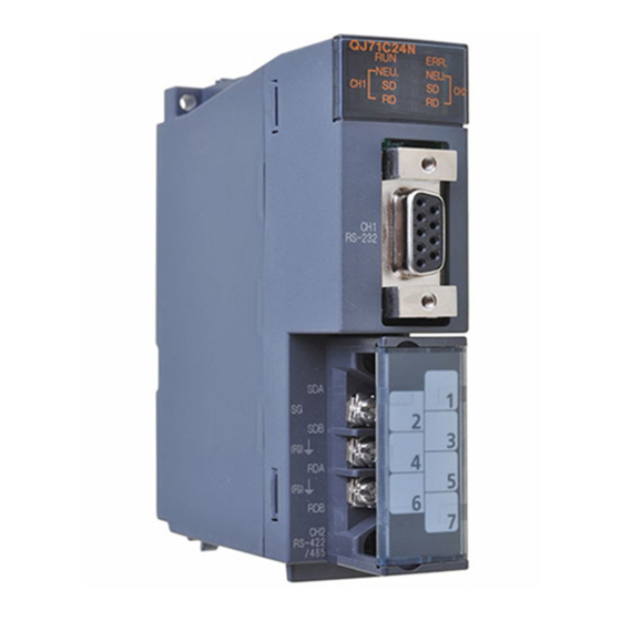
SETTINGS AND PROCEDURES PRIOR TO OPERATION MELSEC-Q 4.3 Part Names and Functions Part names of Q series C24 are shown below. Name Contents Display LED Display LED (For details, see (1).) RS232 interface for serial communication with external RS-232 interface devices (D-Sub 9 pin) RS422/485 interface for serial communication with external RS-422/485 interface... - Page 107 SETTINGS AND PROCEDURES PRIOR TO OPERATION MELSEC-Q (1) LED display list QJ71C24N QJ71C24N-R2 QJ71C24N-R4 ERR. ERR. ERR. NEU. NEU. NEU. NEU. NEU. NEU. Compatible protocol Display contents On/flashing Non- Pre- Bidirectional procedural defined Normal operation display Normal Faulty or reset —...
-
Page 108: External Wiring
FG terminals of both stations. (See section 4.4.2.(6).) When connecting the plug-in socket block to the QJ71C24N-R4, be sure to confirm the layout of the socket block, and then insert it into the RS-422/485 connector on the QJ71C24N-R4. -
Page 109: Connecting The Rs-232 Interface (Full-Duplex Communications)
SETTINGS AND PROCEDURES PRIOR TO OPERATION MELSEC-Q 4.4.1 Connecting the RS-232 interface (full-duplex communications) The following shows the connection precautions and connection examples when using the Q series C24 RS-232 interface for full-duplex communications. (1) Connection precautions (a) For further information about the following items, see the explanation in the applicable section in the User's Manual (Application). - Page 110 SETTINGS AND PROCEDURES PRIOR TO OPERATION MELSEC-Q (2) Connection examples (a) Connection example with an external device capable of turning on and off the CD(DCD) signal (No. 1 pin) The CD terminal check setting is set according to the specification of the external device.
-
Page 111: Connecting The Rs-422/485 Interface
Be sure to use the plate terminals included with the product when connecting the braided shield wire to the QJ71C24N-R4. 2) Connect the (FG) of the Q series C24 side to the FG terminal at the power... - Page 112 110 Brown Brown Brown Brown Orange Orange (d) When connecting the terminal resistor of the QJ71C24N-R4 to the RS- 422/485 plug-in socket block, insert the terminal resistor in the orientation shown below. Correct insertion Inserted vertically. 4 - 9...
- Page 113 SETTINGS AND PROCEDURES PRIOR TO OPERATION MELSEC-Q Incorrect insertion Inserted horizontally. (e) If data cannot be communicated with the external device at all, the polarity of the external device could be wrong and should be checked again. If the polarities of the Q series C24 and the external device do not match, reverse the polarity of each signal on either device side and connect the devices with the cable;...
- Page 114 SETTINGS AND PROCEDURES PRIOR TO OPERATION MELSEC-Q (b) External device and Q series C24 with 1:n (multidrop) system configuration 1) Connection example 1 2) Connection example 2 External device C24 1) C24 2) C24n RS-422/485 RS-422/485 RS-422/485 cable cable cable Terminal resistor (c) External device and Q series C24 with n:1 (multidrop) system configuration...
- Page 115 SETTINGS AND PROCEDURES PRIOR TO OPERATION MELSEC-Q (d) External device and Q series C24 with m:n (multidrop) system configuration 1) Connection example 1 External device 1) External device 2) RS-232 RS-232 C24 1) C24 2) C24n RS-422/485 RS-422/485 cable cable Terminal Linked Linked...
-
Page 116: Settings For Gx Developer
Setting for item Remarks Type Select "intelli.". Model name Enter the module model name to be mounted. (Example: QJ71C24N) Points Select 32 points. Start XY Enter the start I/O signal (Hexadecimal) for the target module. assignment Switch setting Set the communication rate, transmission specifications, See Section 4.5.2. -
Page 117: Switch Settings For I/O And Intelligent Functional Module
SETTINGS AND PROCEDURES PRIOR TO OPERATION MELSEC-Q 4.5.2 Switch settings for I/O and intelligent functional module [Setting purpose] In the switch setting for I/O modules and intelligent functional modules, set the transmission specifications and communication protocols for communication with external devices. [Setting procedure] [PLC parameters] [I/O assignment setting]... - Page 118 SETTINGS AND PROCEDURES PRIOR TO OPERATION MELSEC-Q (a) Transmission setting (CH1 side: switch 1 (lower level); CH2 side: switch 3 (lower level)) CH1 side CH2 side Description OFF (0) ON (1) Remarks Operation setting Independent Link Must be set to OFF on CH1 Data bit Parity bit is not included Parity bit...
- Page 119 SETTINGS AND PROCEDURES PRIOR TO OPERATION MELSEC-Q 4) Even/odd parity setting This sets whether the parity bit (vertical parity) should be odd parity or even parity when adding the parity bit (vertical parity), according to the specifications of the external device. 5) Stop bit setting This sets the stop bit length for one character in data communicated with an external device, according to the specifications of the external device.
- Page 120 115,200 bps is available for the interface (the maximum of 230,400 bps if using QJ71C24N (-R2/R4)). In this case, set 300 bps for the other interface to which no external device is connected.
- Page 121 SETTINGS AND PROCEDURES PRIOR TO OPERATION MELSEC-Q (d) Station number setting (switch 5 (common for both CH1 and CH2 sides)) • This setting is for communication using the MC protocol. • When several the Q series C24s are connected on the same line with multidrop connection, set the station number designated in the data items of the transmission frame in each external device to 0 to 31 (0 to 1F...
- Page 122 (b) Do not use the above settings for the following cases, because linked operation cannot be performed. 1) When using the QJ71C24N-R2 or QJ71C24-R2. 2) When an external device is not connected to either of the interfaces. 3) When using the bidirectional or pre-defined protocol.
- Page 123 SETTINGS AND PROCEDURES PRIOR TO OPERATION MELSEC-Q In linked operation, all data received from one of the two interfaces is transmitted from the other interface. In this case, exclusive control of the received data is necessary when data is communicated using the non- procedure protocol since all the connected stations receive the data.
-
Page 124: The Intelligent Function Module Interrupt Pointer Setting
SETTINGS AND PROCEDURES PRIOR TO OPERATION MELSEC-Q 4.5.3 The Intelligent function module interrupt pointer setting The following explains the interrupt pointer setting with GX Developer in order to receive data using an interrupt program. For how to receive data using an interrupt program, see the User's Manual (Applications). - Page 125 SETTINGS AND PROCEDURES PRIOR TO OPERATION MELSEC-Q (3) Start I/O No. on the intelligent module (unit) side Set the start I/O No. for the Q series C24. (4) Start SI No. on intelligent module (unit) side 1) Assign control numbers (SI) on the Q series C24 side to the interrupt pointers (Ixx) used in the sequence program.
-
Page 126: Settings With The Utility Package (Gx Configurator-Sc)
SETTINGS AND PROCEDURES PRIOR TO OPERATION MELSEC-Q 4.6 Settings with the Utility Package (GX Configurator-SC) The settings defined with GX Configurator-SC for operation of the Q series C24 are described in Chapter 8. The following concerns the data set from GX Configurator-SC. 1) Data set in the Q series C24 for the use of specific functions 2) Data set in the programmable controller CPU to communicate information between the Q series C24 and the programmable controller CPU of the mounting station. - Page 127 SETTINGS AND PROCEDURES PRIOR TO OPERATION MELSEC-Q Point Auto refresh settings can be also set for items not listed below with GX Works2. (Refer to Appendix 1.1 (3).) [Setting items] Buffer memory address Setting item Reference section Flash ROM access register/read/delete result CH1/CH2 LED ON status, communication error status ( Section 9.6.10 Switch setting error, mode switching error status (...
- Page 128 SETTINGS AND PROCEDURES PRIOR TO OPERATION MELSEC-Q (1) Devices (a) Set the word device of the programmable controller CPU which stores information in the setting item field when using the auto refresh function between the Q series C24 and the programmable controller CPU. (b) The devices used must be of the types X, Y, M, L, B, T, C, ST, D, W, R, or If bit devices of types X, Y, M, L, or B are used, a number that can be divided by 16 points (e.g., X30, Y120, M16, etc.) should be specified.
-
Page 129: Individual Station Test
SETTINGS AND PROCEDURES PRIOR TO OPERATION MELSEC-Q 4.7 Individual Station Test After installing the Q series C24 to the base unit of QCPU, perform an individual station test first to check the switch setting (see Section 4.5.2) and operation of the Q series C24. POINT (1) When a problem occurs during data communication with an external device, perform an individual station test as described in this section to check whether... - Page 130 SETTINGS AND PROCEDURES PRIOR TO OPERATION MELSEC-Q (2) Restart the programmable controller CPU station or reset the CPU. The test starts automatically in about one second. (3) For the Q series C24, the following tests should be performed once. 1) ROM check Read the ROM data and verify the sum check.
- Page 131 SETTINGS AND PROCEDURES PRIOR TO OPERATION MELSEC-Q (Procedure 4) Ending a ROM/RAM/switch test (1) Perform the following procedures after checking normal completion/abnormal completion of the test results. Normal completion : Perform operation (2) to finish tests. Upon error occurrence : When an error occurs in a switch check or linked operation setting check, set the correct values and test again.
-
Page 132: Individual Station Loopback Test
SETTINGS AND PROCEDURES PRIOR TO OPERATION MELSEC-Q 4.7.2 Individual station loopback test The individual station loopback test checks the operation of the communication function of the Q series C24. Follow the procedure below to perform an individual station loopback test. (Procedure 1) Connecting cable (1) Connect cables to two interfaces as follows. - Page 133 SETTINGS AND PROCEDURES PRIOR TO OPERATION MELSEC-Q (Procedure 4) Checking the results of an individual loopback test (1) This test is performed repeatedly. When the ERR LED is off, the test is being executed normally. (2) The test is completed with an error when the ERR LED is lit. Check the error description on one of the following screens.
-
Page 134: Loopback Test
SETTINGS AND PROCEDURES PRIOR TO OPERATION MELSEC-Q 4.8 Loopback Test A loopback test performs a communication test using the loopback test function of the MC protocol, in order to check the connection between the Q series C24 and an external device, the communication function of each device, and the operation of the communication program of the external device. - Page 135 SETTINGS AND PROCEDURES PRIOR TO OPERATION MELSEC-Q (Procedure 5) Ending the loopback test Perform the following procedure according to the function used, and start data communication. • Set the switch settings with GX Developer according to the procedure specified in Section 4.5.2.
-
Page 136: Maintenance And Inspection
SETTINGS AND PROCEDURES PRIOR TO OPERATION MELSEC-Q 4.9 Maintenance and Inspection This section explains the maintenance and inspection and installing and removing of the Q series C24. 4.9.1 Maintenance and inspection The Q series C24 has no special inspection items other than below. For items other than listed below, perform inspection according to the inspection items listed in the User's Manual of the programmable controller CPU module in order to always use the system in the optimal condition. -
Page 137: When Mounting/Dismounting The Module
SETTINGS AND PROCEDURES PRIOR TO OPERATION MELSEC-Q 4.9.2 When mounting/dismounting the module Please read 4.1, "Handling Precautions" before mounting or dismounting the module, and make sure to pay attention to safety and handle the module properly during the operation. When replacing the Q series C24 and QCPU, it becomes necessary to register the following data on the Q series C24 again for the module to be replaced. - Page 138 SETTINGS AND PROCEDURES PRIOR TO OPERATION MELSEC-Q MEMO 4 - 35 4 - 35...
-
Page 139: Data Communication Using The Melsec Communication Protocol
5 DATA COMMUNICATION USING THE MELSEC COMMUNICATION PROTOCOL MELSEC-Q 5 DATA COMMUNICATION USING THE MELSEC COMMUNICATION PROTOCOL This chapter explains an overview of the MELSEC communication protocol (hereinafter abbreviated as the MC protocol). See the following manual for a detailed explanation of the data communication functions that are available when using the MC protocol. -
Page 140: Message Format And Control Procedure For Data Communication
5 DATA COMMUNICATION USING THE MELSEC COMMUNICATION PROTOCOL MELSEC-Q (4) Monitoring the programmable controller CPU This function monitors the operating status of the programmable controller CPU and the data in the device memory. The programmable controller CPU status and the device memory data can be sent to the external device at fixed intervals, when an error occurs in the machine equipment, or when certain conditions are satisfied. -
Page 141: Support Of Multiple Cpu System Or Redundant System
5 DATA COMMUNICATION USING THE MELSEC COMMUNICATION PROTOCOL MELSEC-Q (2) System settings using GX Configurator-SC When it is necessary to change the default values registered in the Q series C24, perform the settings as indicated in Chapter 9 and register these to the flash ROM in the Q series C24. -
Page 142: Support For The Qcpu Remote Password Function
5 DATA COMMUNICATION USING THE MELSEC COMMUNICATION PROTOCOL MELSEC-Q 5.1.5 Support for the QCPU remote password function This section explains an overview of the remote password function when a remote password is set for the Q series C24 mounted to a QCPU. See the User's Manual (Application) for a detailed explanation. - Page 143 5 DATA COMMUNICATION USING THE MELSEC COMMUNICATION PROTOCOL MELSEC-Q REMARKS The remote password should be set to a QCPU using GX Developer in order to use the remote password function of QCPU. • Unlocking the remote password is possible only for the QCPU of the local station with the Q series C24.
-
Page 144: Utilizing The Mx Component
5 DATA COMMUNICATION USING THE MELSEC COMMUNICATION PROTOCOL MELSEC-Q (b) Modem function monitor/test by GX Configurator-SC It is possible to monitor the setting values for the remote password and the number of occurrences up to the present. such as the designation of the number of times before notifying an unmatched remote password and the current number of occurrences. -
Page 145: Data Communication Using The Non Procedure Protocol
DATA COMMUNICATION USING THE NON PROCEDURE PROTOCOL MELSEC-Q 6 DATA COMMUNICATION USING THE NON PROCEDURE PROTOCOL Data communication using the non procedure protocol is a function for sending and receiving data between a programmable controller CPU and an external device using the message format and transmission control procedure specified by the user. -
Page 146: Data Reception From The External Device
DATA COMMUNICATION USING THE NON PROCEDURE PROTOCOL MELSEC-Q 6.1 Data Reception from the External Device This section explains data reception from the external device. 6.1.1 Receiving methods The following shows the methods for receiving data in any format using the non- procedure protocol. - Page 147 DATA COMMUNICATION USING THE NON PROCEDURE PROTOCOL MELSEC-Q (1) Data reception by receive complete code (for variable length reception) (a) This method is used to send data by adding the receive complete code set in the Q series C24 at the complete of the message to be sent from the external device.
- Page 148 DATA COMMUNICATION USING THE NON PROCEDURE PROTOCOL MELSEC-Q • If the next data (LF, etc.) is not received within the time set in the non reception monitoring time (timer 0) after CR is received, the Q series C24 stores the received data up to CR to the buffer memory receive data storage area and turns on the following signals to the programmable controller CPU.
- Page 149 DATA COMMUNICATION USING THE NON PROCEDURE PROTOCOL MELSEC-Q (2) Reception by received data count (For fixed length reception) (a) This method is used to receive messages of the same length (size) from the external device every time. (b) When the Q series C24 receives data of the received data count preset in GX Configurator-SC by the user, it sends a reception data read request to the sequence program.
-
Page 150: The Receive Area And The Received Data List
DATA COMMUNICATION USING THE NON PROCEDURE PROTOCOL MELSEC-Q 6.1.2 The receive area and the received data list The following shows the list of the receive area and the receive data for performing data reception using the non procedure protocol. (1) Receive area The receive area is a memory area for storing the data received from the external device and the receive data count in order to read the receive data for the programmable controller CPU. - Page 151 DATA COMMUNICATION USING THE NON PROCEDURE PROTOCOL MELSEC-Q POINT (1) The position and size of the receive area in the buffer memory can be changed with the GX Configurator-SC in accordance with the specifications of the external device and the receive data length. (See Section 9.4.7.) (a) When changing the position and size of the receive area in the buffer memory with GX Configurator-SC, specify as follows: 1) Receive buffer memory head address designation...
- Page 152 DATA COMMUNICATION USING THE NON PROCEDURE PROTOCOL MELSEC-Q (2) Receive data list The following describes the data list when data received from an external device is stored to the receive area. 1) The receive message is stored to the Q series C24 buffer memory (receive data storage area).
- Page 153 DATA COMMUNICATION USING THE NON PROCEDURE PROTOCOL MELSEC-Q REMARKS (1) Data reception when: Receive data storage area > Receive data length The following control is performed. (Example) When the receive area for the CH1 side interface is located at addresses 600 to 7FF (default values) and data of 511 words or less is received by the CH1 side interface.
- Page 154 DATA COMMUNICATION USING THE NON PROCEDURE PROTOCOL MELSEC-Q 2) Reception by received data count If a specified receive data count is too large for the receive data storage area, Receive buffer memory length (address: A7 /147 , default: 512 words) minus 1 is used as the receive data count instead. (Receive data storage area) >...
-
Page 155: Sequence Program For Data Reception
DATA COMMUNICATION USING THE NON PROCEDURE PROTOCOL MELSEC-Q 6.1.3 Sequence program for data reception This section explains the sequence program for data reception. For details on the INPUT instruction for data reception, see Chapter 10. 1 When the completion device is off, execute the INPUT instruction. If the INPUT instruction is executed when the completion device is on, data may not be received properly. - Page 156 DATA COMMUNICATION USING THE NON PROCEDURE PROTOCOL MELSEC-Q 1) Start the self-station programmable controller CPU. The values specified with GX Developer are stored in the Q series C24. 2) When the amount of data specified by the received data count or data containing the receive complete code is received from the external device, the reception data read request (X3) turns ON.
- Page 157 DATA COMMUNICATION USING THE NON PROCEDURE PROTOCOL MELSEC-Q 4) The device completing the INPUT instruction turns ON when the reading of receive data is completed. When the complete device + 1 (abnormal completion signal) turns ON, the error code is stored in the control data completion status (S1 + 1). (Program example) When the Q series C24 I/O signals are from X/Y00 to X/Y1F: Q series C24...
- Page 158 DATA COMMUNICATION USING THE NON PROCEDURE PROTOCOL MELSEC-Q POINT (1) Receive data can also be read using interrupt programs. For more details on reading receive data with interrupt programs, see the User's Manual (Application). Note that if the reading of data received from the same interface is to be performed, it is not possible to combine the reading of data received by the main program and reading of data received by the interrupt program.
-
Page 159: Receive Data Clear
DATA COMMUNICATION USING THE NON PROCEDURE PROTOCOL MELSEC-Q 6.1.4 Receive data clear For the data reception by a non procedure protocol, if the transmission of data from a transmitting device is interrupted due to trouble occurring, it may be necessary for the data received up to the present time are cleared in the receiving device and for the data to be received again from the start. - Page 160 DATA COMMUNICATION USING THE NON PROCEDURE PROTOCOL MELSEC-Q The following is a program example of clearing the reception data by the dedicated instruction "CSET". Set the execution type Set the request type (Reception data clear) Execute the reception data clear Normal completion Abnormal completion Reset the complete flag by...
- Page 161 DATA COMMUNICATION USING THE NON PROCEDURE PROTOCOL MELSEC-Q Send request execution disabled Dedicated instruction Receive Q series C24 for sending execution data clear processing disabled, too Receive data clear request "0" "1" "0" (address: A8 Programmable TO instruction controller (Write "1" to address A8H) CPU (Program) 6 - 17 6 - 17...
- Page 162 DATA COMMUNICATION USING THE NON PROCEDURE PROTOCOL MELSEC-Q (Example) The following is an example program for clearing received data with the FROM/TO instructions while send/receive processing is performed using dedicated instructions (OUTPUT/INPUT). 1 Add the dotted line portion to the sequence program when the function version A Q series C24 is used.
-
Page 163: How To Detect Reception Errors
DATA COMMUNICATION USING THE NON PROCEDURE PROTOCOL MELSEC-Q 6.1.5 How to detect reception errors This section explains how to detect errors that may occur when receiving data from the external device. The following items are considered as the primary causes of errors that may occur during data reception. - Page 164 DATA COMMUNICATION USING THE NON PROCEDURE PROTOCOL MELSEC-Q (2) Confirmation using the module and GX Configurator-SC 1) Confirmation using the display LED When the Q series C24 detects an error, including a transmission error, the ERR LED lights up. (See Chapter 11.) 2) Confirmation using GX Configurator-SC •...
- Page 165 DATA COMMUNICATION USING THE NON PROCEDURE PROTOCOL MELSEC-Q Programmable Q series C24 controller Receive area Reception error causing data Q25HCPU Reception (buffer memory) MODE. Receive data abnormal RUN. Receive ERR. count storage detection USER. Head data complete code area BAT. BOOT.
-
Page 166: Received Data Count And Receive Complete Code Settings
DATA COMMUNICATION USING THE NON PROCEDURE PROTOCOL MELSEC-Q 6.1.6 Received data count and receive complete code settings The following default values have been set for the received data count and receive complete code that are used for data reception with the non procedure protocol. The received data count and the receive complete code setting value can be changed by the sequence program before data receive processing. - Page 167 DATA COMMUNICATION USING THE NON PROCEDURE PROTOCOL MELSEC-Q (2) Setting values that can be changed Of the initial settings from GX Configurator-SC stored in the buffer memory, only the following setting values can be changed after data communication has started. •...
-
Page 168: Sending Data To The External Device
DATA COMMUNICATION USING THE NON PROCEDURE PROTOCOL MELSEC-Q 6.2 Sending Data to the External Device This section explains data transmission from the programmable controller CPU to the external device. 6.2.1 Transmission methods The following shows how to send data in any format using the non procedure protocol. Programmable controller CPU Transmission data ) (41... -
Page 169: Arrangement And Contents Of The Transmission Area And The Transmission Data
DATA COMMUNICATION USING THE NON PROCEDURE PROTOCOL MELSEC-Q 6.2.2 Arrangement and contents of the transmission area and the transmission data This section explains the arrangement and contents of the transmission area and the transmission data for performing data transmission using the non procedure protocol. (1) Transmission area The transmission area is a memory area for storing the data and the data count that are transmitted from the programmable controller CPU to the external device... - Page 170 DATA COMMUNICATION USING THE NON PROCEDURE PROTOCOL MELSEC-Q POINT (1) The position and size of the transmission area in the buffer memory can be changed with GX Configurator-SC in accordance with the specifications of the external device and the received data length. (See Sections 9.4.5 and 9.4.7.) (a) When changing the position and size of the transmission area in the buffer memory with GX Configurator-SC, specify as follows: 1) Transmission buffer memory head address designation...
-
Page 171: Sequence Program For Transmission Data
DATA COMMUNICATION USING THE NON PROCEDURE PROTOCOL MELSEC-Q (2) Transmission data arrangement The following example shows an arrangement of the transmission data to be sent to the external device when storing it in the transmission area. (Example) When transmitting "ABCDEFG123" (The transmit area is the default value.) CH1 side address... - Page 172 DATA COMMUNICATION USING THE NON PROCEDURE PROTOCOL MELSEC-Q Q series C24 ready (X1E) Transmission instruction OUTPUT instruction OUTPUT OUTPUT instruction complete device ON when transmission abnormal completion OUTPUT instruction complete device + 1 (normal completion/abnormal 1 scan completion) Transmission data count designation (address: 400 Transmission data Transmission data...
- Page 173 DATA COMMUNICATION USING THE NON PROCEDURE PROTOCOL MELSEC-Q (Program example) When Q series C24 I/O signals are from X/Y00 to X/Y1F: The transmission command is converted into pulse. Transmission data is stored. Designate the number of the interface(CH ) that will send the data.
-
Page 174: How To Detect Transmission Errors
DATA COMMUNICATION USING THE NON PROCEDURE PROTOCOL MELSEC-Q 6.2.4 How to detect transmission errors This section explains how to detect errors that may occur when sending data to the external device. The following items are considered as the primary causes of errors that may occur during data transmission. - Page 175 DATA COMMUNICATION USING THE NON PROCEDURE PROTOCOL MELSEC-Q (2) Confirmation using the module and GX Configurator-SC 1) Confirmation using the display LED When the Q series C24 detects an error, including a transmission error, the ERR LED lights up. (See Chapter 11.) 2) Confirmation using GX Configurator-SC •...
-
Page 176: Data Communications Precautions
DATA COMMUNICATION USING THE NON PROCEDURE PROTOCOL MELSEC-Q 6.3 Data Communications Precautions The following describes the precautions to be taken during non procedure protocol data communications. (1) The Q series C24 transmission sequence initialization conditions The initial status indicates the status where transmission has stopped and reception data has been discarded. - Page 177 DATA COMMUNICATION USING THE NON PROCEDURE PROTOCOL MELSEC-Q (4) Retry processing for data reception errors The data when reception error occurred is discarded and only the data for the normal reception is taken into the Q series C24. For this reason, the reception message may be missing data when an error occurs.
-
Page 178: Data Communication Using The Bidirectional Protocol
7 DATA COMMUNICATION USING THE BIDIRECTIONAL PROTOCOL MELSEC-Q 7 DATA COMMUNICATION USING THE BIDIRECTIONAL PROTOCOL Data communication using the bidirectional protocol is a function for sending/receiving any data using the message format and transmission control procedure for the Q series C24 bidirectional protocol between external devices and programmable controller CPUs. -
Page 179: Data Reception From The External Device
DATA COMMUNICATION USING THE BIDIRECTIONAL PROTOCOL MELSEC-Q 7.1 Data Reception from the External Device This section explains the data reception from the external device. 7.1.1 Receiving methods The following shows how to receive data sent from the external device using the bidirectional protocol. - Page 180 DATA COMMUNICATION USING THE BIDIRECTIONAL PROTOCOL MELSEC-Q 1) When the control code ENQ is received, the Q series C24 starts data reception processing. When the data specified by the data length is received, the Q series C24 ends the reception processing of that data. If "Sum check"...
-
Page 181: Arrangement And Contents Of The Receive Area And The Receive Data
DATA COMMUNICATION USING THE BIDIRECTIONAL PROTOCOL MELSEC-Q 7.1.2 Arrangement and contents of the receive area and the receive data This section shows the arrangement and contents of the receive area and the receive data for performing data reception using the bidirectional protocol. (1) Receive area The receive area is a memory that stores the received data length (receive data count) and data area received from an external device. - Page 182 DATA COMMUNICATION USING THE BIDIRECTIONAL PROTOCOL MELSEC-Q POINT (1) The position and size of the receive area in the buffer memory can be changed with GX Configurator-SC in accordance with the specifications of the external device and the received data length. (See Sections 9.4.5 and 9.4. 8.) (a) When changing the position and size of the receive area in the buffer memory with GX Configurator-SC, specify as follows: 1) Receive buffer memory head address designation...
- Page 183 DATA COMMUNICATION USING THE BIDIRECTIONAL PROTOCOL MELSEC-Q (2) Arrangement of receive data The following example illustrates the arrangement of data received from the external device when it is stored in the receive area. 1) The receive message is stored to the Q series C24 buffer memory (receive data storage area).
- Page 184 DATA COMMUNICATION USING THE BIDIRECTIONAL PROTOCOL MELSEC-Q (b) Data length This indicates the number of bytes or words for the data portion of the message. The unit of data length (words/bytes) is in accordance with the word/byte units designation in GX Configurator-SC. 1) For data communication from the external device to the Q series C24 The Q series C24 checks the length of the data received.
- Page 185 DATA COMMUNICATION USING THE BIDIRECTIONAL PROTOCOL MELSEC-Q (d) Sum check code The sum check code expresses the numeric value for the lower two bytes (16 bits) of the results (sum) from the addition of the data length and the data portion in the message as binary code data. When "Sum check"...
- Page 186 DATA COMMUNICATION USING THE BIDIRECTIONAL PROTOCOL MELSEC-Q (e) Error code The error code indicates the definition of the error during NAK response. (For more details on the error codes, see Chapter 11.) 1) For data communication from the external device to the Q series C24 For error codes from the external device, transmit the codes specified by the user.
-
Page 187: Sequence Program For Data Reception
DATA COMMUNICATION USING THE BIDIRECTIONAL PROTOCOL MELSEC-Q 7.1.3 Sequence program for data reception This section explains the sequence program for data reception. For details on the BIDIN instruction for data reception, see Chapter 10. X3 Read request (CH1) Create control data from D0 G.BIDIN Processing for normal completion (stores receive data, etc.) - Page 188 DATA COMMUNICATION USING THE BIDIRECTIONAL PROTOCOL MELSEC-Q (Program example) When Q series C24 I/O signals are from X/Y00 to X/Y1F: Designate the receive channel. Clear the receive data count storage device to 0. Designate the allowable receive data count. With the normal completion, the receive data within the allowable receive data count (user designated) is read from the receive data storage area in the buffer memory.
- Page 189 DATA COMMUNICATION USING THE BIDIRECTIONAL PROTOCOL MELSEC-Q POINT (1) Receive data can also be read using interrupt programs. For more details on reading receive data with interrupt programs, see the User's Manual (Application). Note that if the reading of data received from the same interface is to be performed, it is not possible to combine the reading of data received by the main program and reading of data received by the interrupt program.
-
Page 190: How To Detect Reception Errors
DATA COMMUNICATION USING THE BIDIRECTIONAL PROTOCOL MELSEC-Q 7.1.4 How to detect reception errors This section explains how to detect errors that may occur when receiving data from the external device. The following items are considered as the primary causes of errors that may occur during data reception. -
Page 191: Receive Data Clear
DATA COMMUNICATION USING THE BIDIRECTIONAL PROTOCOL MELSEC-Q (2) Confirmation using the module and GX Configurator-SC 1) Confirmation using the display LED When the Q series C24 detects an error, including a transmission error, the ERR LED lights up. (See Chapter 11.) 2) Confirmation using GX Configurator-SC •... -
Page 192: Sending Data To The External Device
DATA COMMUNICATION USING THE BIDIRECTIONAL PROTOCOL MELSEC-Q 7.2 Sending Data to the External Device This section explains data transmission from the programmable controller CPU to the external device. 7.2.1 Transmission methods The following shows the method of sending data to the external device through data communication using the bidirectional protocol. -
Page 193: Arrangement And Contents Of The Transmission Area And The Transmission Data
DATA COMMUNICATION USING THE BIDIRECTIONAL PROTOCOL MELSEC-Q 7.2.2 Arrangement and contents of the transmission area and the transmission data This section explains the arrangement and contents of the transmission area and the transmission data for performing data transmission using the bidirectional protocol. For details on the contents of transmission data, see Section 7.1.2 (3). - Page 194 DATA COMMUNICATION USING THE BIDIRECTIONAL PROTOCOL MELSEC-Q POINT (1) The position and size of the transmission area in the buffer memory can be changed with GX Configurator-SC in accordance with the specifications of the external device and the transmission data length. (See Section 9.4.5.) (a) When changing the position and size of the transmission area in the buffer memory with GX Configurator-SC, designate as follows: 1) Transmission buffer memory head address designation...
- Page 195 DATA COMMUNICATION USING THE BIDIRECTIONAL PROTOCOL MELSEC-Q (2) Transmission data arrangement The following example shows an arrangement of the transmission data to be sent to the external device when storing it in the transmission area. (Example) When "ABCDEFG123" is sent: Q series C24 Transmission area Transmission data (response message)
-
Page 196: Sequence Program For Data Transmission
DATA COMMUNICATION USING THE BIDIRECTIONAL PROTOCOL MELSEC-Q 7.2.3 Sequence program for data transmission A sequence program for data transmission is explained below. For details on the BIDOUT instruction for data transmission, see Chapter 10. Transmission (In case of the CH1 side) instruction Create transmission data from D11 Create control data from D0... - Page 197 DATA COMMUNICATION USING THE BIDIRECTIONAL PROTOCOL MELSEC-Q 1) Starts the local station programmable controller. The setting values for GX Developer are stored in the Q series C24. 2) Inputs the user data transmission instruction signal. 3) Executes the BIDOUT instruction after storing the transmission data and the control data for the BIDOUT instruction in the device.
- Page 198 DATA COMMUNICATION USING THE BIDIRECTIONAL PROTOCOL MELSEC-Q Q series C24 Address Buffer memory Data transmission result For normal completion Interface number (0001 Transmission data count designation Transmission result (0000 Transmission data count (0005 Transmission data designation (4241 Transmission data (0A0D For abnormal completion Interface number (0001...
-
Page 199: How To Detect Transmission Errors
DATA COMMUNICATION USING THE BIDIRECTIONAL PROTOCOL MELSEC-Q 7.2.4 How to detect transmission errors This section explains how to detect errors that may occur when sending data to the external device. The following items are considered as the primary causes of errors that may occur during data transmission. - Page 200 DATA COMMUNICATION USING THE BIDIRECTIONAL PROTOCOL MELSEC-Q (2) Confirmation using the module and GX Configurator-SC 1) Confirmation using the display LED When the Q series C24 detects an error, including a reception error, the ERR LED lights up. (See Chapter 11.) 2) Confirmation using GX Configurator-SC •...
-
Page 201: Processing When Simultaneous Transmission Performed During Full-Duplex Communications
DATA COMMUNICATION USING THE BIDIRECTIONAL PROTOCOL MELSEC-Q 7.3 Processing when Simultaneous Transmission Performed During Full-Duplex Communications This section explains the processing when simultaneous transmissions occur in full- duplex communication. 7.3.1 Processing when simultaneous transmissions occur This section explains the processing performed by the Q series C24 when the external device and the Q series C24 transmit at the same time during data communications using the bidirectional protocol. -
Page 202: Communication Data Processing When Simultaneous Transmissions Occur
DATA COMMUNICATION USING THE BIDIRECTIONAL PROTOCOL MELSEC-Q 7.3.2 Communication data processing when simultaneous transmissions occur Examples of the Q series C24 communication data processing for various settings of "Simultaneous transmission data valid/invalid designation" by GX Configurator-SC are explained. (1) Transmission: valid, reception: valid 2)-1 1)-2 Sum check... - Page 203 DATA COMMUNICATION USING THE BIDIRECTIONAL PROTOCOL MELSEC-Q (4) Transmission: invalid, reception: invalid 2)-1 Sum check Arbitrary data code Ignores the receive External device data of 1)-1. Generates a simultaneous Q series C24 transmission error. Sum check Arbitrary data Ignores the receive data of 2)-1. code 1)-1 REMARKS...
-
Page 204: Data Communications Precautions
DATA COMMUNICATION USING THE BIDIRECTIONAL PROTOCOL MELSEC-Q 7.4 Data Communications Precautions The following are the precautions when performing data communications using the bidirectional protocol. (1) When the transmission sequence is in the initial status, it indicates that data transmission and reception processing has not been started. The Q series C24 transmission sequence is initialized in the following cases. - Page 205 DATA COMMUNICATION USING THE BIDIRECTIONAL PROTOCOL MELSEC-Q POINT (1) Perform error processing according to the error code received immediately after the NAK message at the device that received NAK as the response message after data transmission. Chapter 11 shows the error codes that are transmitted from the Q series C24. (2) If the Q series C24 receives an NAK response while transmitting data to an external device, it completes data transmission, then reads the NAK, perform abnormal completion.
-
Page 206: Data Communication Using The Pre-Defined Protocol
DATA COMMUNICATION USING THE PRE-DEFINED PROTOCOL MELSEC-Q 8 DATA COMMUNICATION USING THE PRE-DEFINED PROTOCOL Data can be transferred between the QJ71C24N(-R2/R4) and an external device using GX Configurator-SC (Pre-defined protocol support function) with a protocol appropriate to the external device. - Page 207 • Packet element (packet format) • Packet data • Communication type (Send only, Receive only, or Send and receive) The function cannot be used when the QJ71C24N(-R2/R4) is used with the following modules. • Redundant CPU • C Controller module •...
-
Page 208: Function Of The Pre-Defined Protocol
DATA COMMUNICATION USING THE PRE-DEFINED PROTOCOL MELSEC-Q 8.1 Function of the Pre-Defined Protocol The function of the pre-defined protocol is listed below. Function Description Reference Operating Manual Data communication with Data can be sent and received using the protocol of the (Pre-defined protocol external device external device. - Page 209 DATA COMMUNICATION USING THE PRE-DEFINED PROTOCOL MELSEC-Q (From the previous page) Step 3: Write the protocol setting data to the flash ROM. Select a target module, and write the protocol setting data to the flash ROM. Step 4: Execute the protocol with a dedicated instruction. Set values are in the Send data storage area.
-
Page 210: Pre-Defined Protocol System Setting
DATA COMMUNICATION USING THE PRE-DEFINED PROTOCOL MELSEC-Q 8.1.2 Pre-defined protocol system setting In the "Pre-defined protocol system setting" window of GX Configurator-SC (Intelligent function module utility), register the system setting value for data communication with the pre-defined protocol. For information on how to display the setting screen, refer to Section 9.4.9. [Setting screen] [Setting item] Item... -
Page 211: Pre-Defined Protocol Monitor/Test
DATA COMMUNICATION USING THE PRE-DEFINED PROTOCOL MELSEC-Q 8.1.3 Pre-defined protocol monitoring/test In the "Pre-defined protocol monitor/test" window of GX Configurator-SC (Intelligent function module utility), the pre-defined protocol execution status and an error code can be confirmed. [Confirmation procedure] 1) Display the "Pre-defined protocol monitor/test" window. For information on how to display this window, refer to Section 9.6.7. -
Page 212: Protocol Execution Log Storage Function
DATA COMMUNICATION USING THE PRE-DEFINED PROTOCOL MELSEC-Q 8.1.4 Protocol execution log storage function The protocol execution log storage function allows you to confirm the detailed pre- defined protocol execution status and results for each channel. Up to 32 protocol execution logs can be checked. If the number of the stored logs exceeds 32, the oldest log will be overwritten. -
Page 213: Executing Condition Of Predefined Protocol Communication
X1D turns on when the written data are normal. Performed by the user Performed by the Writing protocol setting QJ71C24N(-R2/R4) data to the flash ROM Predefined protocol Turns ON if the protocol ready (X1D) setting data are normal. - Page 214 DATA COMMUNICATION USING THE PRE-DEFINED PROTOCOL MELSEC-Q (2) Timing for executing the UINI instruction or mode switching request signal (Y2/Y9) (a) Timing for executing mode switching request signal (Y2/Y9) Communication protocol before change: CH1 and CH2 are other than the predefined protocol mode. Communication protocol after change: CH1 or CH2 is the predefined protocol mode.
- Page 215 DATA COMMUNICATION USING THE PRE-DEFINED PROTOCOL MELSEC-Q Communication protocol before change: CH1 or CH2 is the predefined protocol mode. Communication protocol after change: CH1 and CH2 are other than the predefined protocol mode. Mode switching request (Y2/Y9) Mode switching (X6/XD) Predefined protocol ready (X1D)
- Page 216 CH1 or CH2 is in CH1 and CH2 are not in predefined protocol mode. predefined protocol mode. Setting processing QJ71C24N(-R2/R4) Communication not possible Communication protocol before change: CH1 or CH2 is the predefined protocol mode. Communication protocol after change: CH1 or CH2 is the predefined protocol mode.
- Page 217 One scan device Mode switching signal (X6/XD) Predefined CH1 or CH2 is in protocol predefined protocol mode. ready (X1D) CH1 and CH2 are not in predefined protocol mode. QJ71C24N(-R2/R4) Setting processing Communication not possible 8 - 12 8 - 12...
-
Page 218: Programming Example
The system configuration and wiring example are as follows. (a) System configuration example The QJ71C24N to be used should be mounted on the slot 0 on the base unit and connected to the external device on a one-on-one basis using CH2 via RS-422/485 line. - Page 219 QJ71C24N and the target device. (a) Target device and protocols Connect the QJ71C24N and the inverter and read out the operation mode values of the inverter. Set the inverter station number to CPU device (D300) and send it, and store the operation mode value in CPU device (D201).
- Page 220 On the project window on GX Developer, double-click "PLC Parameter". Click the "I/O assignment" tab. Set the following items on the slot where the QJ71C24N has been mounted. [Setting screen] [Display details]...
- Page 221 DATA COMMUNICATION USING THE PRE-DEFINED PROTOCOL MELSEC-Q • Switch setting for intelligent function module Set the transmission specifications and communication protocols with external devices. Set items as follows and click the End button. [Display details] Item Setting Setting details value Input format HEX.
- Page 222 DATA COMMUNICATION USING THE PRE-DEFINED PROTOCOL MELSEC-Q (b) Setting on GX Configurator-SC (pre-defined protocol support function) Set the protocol explained in Section 13.5.2. From the menu bar, select [File][New]. The "Add protocol" screen is displayed. Select the following protocol, and click the OK button. The "Protocol setting"...
- Page 223 DATA COMMUNICATION USING THE PRE-DEFINED PROTOCOL MELSEC-Q The "Element setting – Conversion variable" screen is displayed. In the "Send data storage area" field, enter "D300". Click the OK button. The "Packet setting" screen is displayed. The packet setting of "Packet name" H7B:RD Operation Mode has been completed.
- Page 224 DATA COMMUNICATION USING THE PRE-DEFINED PROTOCOL MELSEC-Q (c) Writing data to module Select [Module read/write] [Write to module]. Select the following module and click the Execute button. The following confirmation message is displayed when writing the protocol setting data to the module is completed. 8 - 19 8 - 19...
- Page 225 Switch the CPU module to RUN, and execute the registered protocol by the dedicated instruction (CPRTCL instruction). The following table shows the devices to be used. • I/O signal of QJ71C24N Predefined protocol ready: X1D • Devices used in program example...
- Page 226 DATA COMMUNICATION USING THE PRE-DEFINED PROTOCOL MELSEC-Q Checking protocol execution result Select [Debugging support function] [Protocol execution log]. On the "Protocol execution log" screen, the execution result of the protocol can be checked. Point The registration conditions of the logs can be specified in Protocol execution log specification (buffer memory address: 40E2 , 40F2 ) and can be set on the...
-
Page 227: Utility Package (Gx Configurator-Sc)
UTILITY PACKAGE (GX Configurator-SC) MELSEC-Q 9 UTILITY PACKAGE (GX Configurator-SC) GX Configurator-SC is a tool that supports the production of necessary sequence programs with initial setting, monitoring and testing, and data communication processing of the Q series C24. GX Configurator-SC is composed of the following utilities: •... - Page 228 UTILITY PACKAGE (GX Configurator-SC) MELSEC-Q (3) Pre-defined protocol support function The Pre-defined protocol support function is offered for the QJ71C24N(-R2/R4) to use the pre-defined protocol communication. Protocol settings required for data communication can be configured easily by selecting any options on the protocol selection screen and writing the data to the flash ROM.
-
Page 229: Functions Available With Utility Package
UTILITY PACKAGE (GX Configurator-SC) MELSEC-Q 9.1 Functions Available with Utility Package The following table lists the utility package function. : indicates that the setting is valid with the applicable protocol.) Pre- Bidirectional Explanation Function procedure defined Remarks protocol page protocol protocol Refresh the Q series C24's error codes and set devices on Auto refresh setting... -
Page 230: Installing And Uninstalling The Utility Package
UTILITY PACKAGE (GX Configurator-SC) MELSEC-Q 9.2 Installing and Uninstalling the Utility Package For how to install or uninstall the utility package, refer to "Method of installing the MELSOFT Series" included in the utility package. 9.2.1 Handling precautions The following explains the precautions on using the utility package. (1) For safety Since the utility package is add-in software for GX Developer, read "Safety Precautions"... - Page 231 The number of parameters that can be set for one module in GX Configurator-SC is as listed below. Target Module Initial setting Auto refresh setting QJ71C24N 0 (Not used) 48 (Max.) QJ71C24N-R2 0 (Not used) 49 (Max.) QJ71C24N-R4 0 (Not used) 48 (Max.)
- Page 232 UTILITY PACKAGE (GX Configurator-SC) MELSEC-Q Example) Counting the number of parameter settings in Auto refresh setting This one row is counted as one setting. Blank rows are not counted. Count up all the setting items on this screen, and add the total to the number of settings for other intelligent function modules to get a grand total.
-
Page 233: Operating Environment
UTILITY PACKAGE (GX Configurator-SC) MELSEC-Q 9.2.2 Operating environment This section describes the operating environment of the personal computer that runs GX Configurator-SC. Item Description Installation (add-in) target GX Developer Version 4 (English version) or later Personal computer A personal computer on which one of the following Microsoft Windows operates Refer to "Operating system and performance required for a personal computer"... - Page 234 UTILITY PACKAGE (GX Configurator-SC) MELSEC-Q (1) Operating system and performance required for a personal computer Performance required for a personal computer Operating system Memory Windows 95 (Service Pack 1 or later) Pentium 133MHz or more 32MB or more Windows Pentium 133MHz or more 32MB or more Windows...
-
Page 235: Utility Package Operation
UTILITY PACKAGE (GX Configurator-SC) MELSEC-Q 9.3 Utility Package Operation 9.3.1 Operation overview GX Developer screen POINT The following settings must be performed before starting the intelligent function module utility: • Set the project using GX Developer • Set "QCPU (Q mode)" for the PC series. [Tools] –... - Page 236 UTILITY PACKAGE (GX Configurator-SC) MELSEC-Q 1) When using online operation 2) When setting auto refresh Auto refresh Select [Online] – [Monitor/Test] from the menu bar. Enter "Start I/O No.", and select "Module type" and "Module model name". Select monitor/test module screen Auto refresh setting screen See Screen 4.6 Monitor/Test...
- Page 237 UTILITY PACKAGE (GX Configurator-SC) MELSEC-Q REMARKS The following diagram illustrates the overview of a procedure in which GX Configurator-SC is used to change the system setting values of the Q series C24 and save the new values to a file or write them to the Q series C24's flash ROM. Start Do you wish to Go to 1) setting via online operation...
- Page 238 UTILITY PACKAGE (GX Configurator-SC) MELSEC-Q 1) (Online operation) [Select a target intelligent function module] screen Start the [Monitor/Test] screen. See Section 9.3.1 Is the original data saved? Is the data saved in a file? Read the data from the module's flash ROM. Read the data from the file.
-
Page 239: Starting The Intelligent Function Module Utility
UTILITY PACKAGE (GX Configurator-SC) MELSEC-Q 9.3.2 Starting the Intelligent function module utility [Operating procedure] Intelligent function module utility is started from GX Developer. [Tools] [Intelligent function utility] [Start] [Setting screen] [Explanation of items] (1) Activation of other screens The following screens can be displayed from the intelligent function module utility screen. - Page 240 UTILITY PACKAGE (GX Configurator-SC) MELSEC-Q (2) Command buttons Initial setting : Cannot be selected. Auto refresh : Starts the auto refresh setting screen. Delete : Deletes the initial setting and auto refresh setting of the selected module. Exit : Close this screen. (3) Menu bar (a) File menu Intelligent function module parameters of the project opened by GX...
- Page 241 UTILITY PACKAGE (GX Configurator-SC) MELSEC-Q POINT (1) Saving intelligent function module parameters in a file Since files cannot be saved using the GX Developer project saving operation, save the files using the "Select a target intelligent function module" screen shown above. (2) Reading/writing intelligent function module parameters from/to a programmable controller using GX Developer (a) Intelligent function module parameters can be read from and written into a...
-
Page 242: Common Utility Package Operations
UTILITY PACKAGE (GX Configurator-SC) MELSEC-Q 9.3.3 Common utility package operations This section explains how to perform the common operations in the data setting, auto refresh setting and monitor/test screens. (1) Control keys Special keys that can be used for operation of the utility package and their applications are listed in the table below. - Page 243 UTILITY PACKAGE (GX Configurator-SC) MELSEC-Q : Closes the screen that is currently open and returns Close to the previous screen. : Saves/writes the system setting data, closes the End setup current screen, and returns to the previously displayed screen. With offline operation, only [Save file] and [Load file] are enabled.
-
Page 244
UTILITY PACKAGE (GX Configurator-SC) MELSEC-Q
(a) This means the data set in Flash ROM setting and they can be stored in any directory separately from projects of GX Developer. (b) Steps 4) and 5) in Figure 9.1 are performed as follows: 4) This operation can be executed from the [Flash ROM setting] screen or [Monitor/Test] screen of the utility. -
Page 245: System Registration To Flash Rom
UTILITY PACKAGE (GX Configurator-SC) MELSEC-Q 9.4 System Registration to Flash ROM [Purpose] Display the menu screen for flash ROM registration, which is used to change the initial values set in the Q series C24's buffer memory. [Operating procedure] • Online operation Startup from Intelligent function module utility (GX Developer Version 4 or later) [Online]... - Page 246 UTILITY PACKAGE (GX Configurator-SC) MELSEC-Q [Setting Items] The following table lists the selection menus for system setting/registration to be displayed: Function Section Remarks User frame registration Section 9.4.1 Data for modem initialization registration Section 9.4.2 Data for modem connection registration Section 9.4.3 Modem function system setting Section 9.4.4...
-
Page 247: User Frame Registration
UTILITY PACKAGE (GX Configurator-SC) MELSEC-Q 9.4.1 User frame registration [Purpose] Register the user frame used in the following functions: • On-demand function using the MC protocol. • Data transmission/receive function using the non procedure protocol. [Operating procedure] • Online operation [Monitor] screen User frame •... -
Page 248: Data For Modem Initialization Registration
UTILITY PACKAGE (GX Configurator-SC) MELSEC-Q 9.4.2 Data for modem initialization registration [Purpose] Register the data for initializing the modem connected to the Q series C24. [Operating procedure] • Online operation [Monitor] screen Data for user modem initialization • Offline operation [Flash ROM setting] screen Data for user modem initialization [Setting screen]... -
Page 249: Data For Modem Connection Registration
UTILITY PACKAGE (GX Configurator-SC) MELSEC-Q 9.4.3 Data for modem connection registration [Purpose] For data communication and notification using the modem function, register the data for connection with external devices. [Operating procedure] • Online operation [Monitor] screen Data for modem connection •... -
Page 250: Modem Function System Setting/Registration
UTILITY PACKAGE (GX Configurator-SC) MELSEC-Q 9.4.4 Modem function system setting/registration [Purpose] For data communication using the modem function, register system setting values. [Operating procedure] • Online operation [Monitor] screen Modem function system setting • Offline operation [Flash ROM setting] screen Modem function system setting [Setting screen] [Setting items]... -
Page 251: Transmission Control And Others System Setting
UTILITY PACKAGE (GX Configurator-SC) MELSEC-Q 9.4.5 Transmission control and others system setting [Purpose] For data communication with external devices, register system setting values for the transmission control method, monitoring time, and buffer memory assignment. [Operating procedure] • Online operation [Monitor] screen Transmission control system setting •... - Page 252 UTILITY PACKAGE (GX Configurator-SC) MELSEC-Q [Setting items] Buffer memory address Item Reference section DTR/DSR (ER/DR), DC control designation DC1/DC3 (Xon/Xoff) code designation User's Manual (Application) DC2/DC4 code designation Communication system designation Section 3.2 CD terminal check designation Half-duplex communications control designation Simultaneous transmission priority/non-priority designation User's Manual (Application) Half-duplex communications control designation...
-
Page 253: Mc Protocol System Setting
UTILITY PACKAGE (GX Configurator-SC) MELSEC-Q 9.4.6 MC protocol system setting [Purpose] For data transmission using the MC protocol, register system setting values. [Operating procedure] • Online operation [Monitor] screen MC protocol system setting • Offline operation [Flash ROM setting] screen MC protocol system setting [Setting screen] [Setting items]... -
Page 254: Non Procedure System Setting
UTILITY PACKAGE (GX Configurator-SC) MELSEC-Q 9.4.7 Non procedure system setting [Purpose] For data transmission using the non procedure protocol, register system setting values. [Operating procedure] • Online operation [Monitor] screen Non procedure system setting • Offline operation [Flash ROM setting] screen Non procedure system setting [Setting screen] [Setting items]... -
Page 255: Bidirectional System Setting
UTILITY PACKAGE (GX Configurator-SC) MELSEC-Q 9.4.8 Bidirectional system setting [Purpose] For data transmission using the bidirectional protocol, register system setting values. [Operating procedure] • Online operation [Monitor] screen Bidirectional system setting • Offline operation [Flash ROM setting] screen Bidirectional system setting [Setting screen] [Setting item] Buffer memory address... -
Page 256: Pre-Defined Protocol System Setting
UTILITY PACKAGE (GX Configurator-SC) MELSEC-Q 9.4.9 Pre-defined protocol system setting [Purpose] For data communication using the pre-defined protocol, register system setting values. [Operating procedure] • Online operation [Monitor] screen Pre-defined protocol system setting • Offline operation [Flash ROM setting] screen Pre-defined protocol system setting [Setting screen] [Setting item]... -
Page 257: Programmable Controller Cpu Monitoring System Setting
UTILITY PACKAGE (GX Configurator-SC) MELSEC-Q 9.4.10 Programmable controller CPU monitoring system setting [Purpose] Register system setting values to use the programmable controller CPU monitoring function. [Operating procedure] • Online operation [Monitor] screen Monitoring system setting • Offline operation [Flash ROM setting] screen Monitoring system setting [Setting screen] 9 - 31... - Page 258 UTILITY PACKAGE (GX Configurator-SC) MELSEC-Q [Setting items] Buffer memory address Setting item Reference section Cycle time units designation 2040 2140 Cycle time designation 2041 2141 PLC CPU monitoring function designation 2042 2142 PLC CPU monitoring transmission measure designation 2043 2143 Transmission pointer designation 2044 2144...
-
Page 259: Transmission User Frame No. Designation System Setting
UTILITY PACKAGE (GX Configurator-SC) MELSEC-Q 9.4.11 Transmission user frame No. designation system setting [Purpose] Register the output frame number to transmit data with the non procedure protocol using the user frame. [Operating procedure] • Online operation [Monitor] screen Output frame system setting •... -
Page 260: Resetting The Buffer Memory/Flash Rom Setting Values To The Default Values
UTILITY PACKAGE (GX Configurator-SC) MELSEC-Q 9.4.12 Resetting the buffer memory/flash ROM setting values to the default values This section explains how to reset the values set in the buffer memory/flash ROM to their default values. [Startup procedure] [Online] [Monitor/Test] "Select monitor/Test module" Monitor/Test [Monitor] screen [Operating procedure]... -
Page 261: Auto Refresh Setting
UTILITY PACKAGE (GX Configurator-SC) MELSEC-Q 9.5 Auto Refresh Setting The auto refresh settings are used to automatically store information stored in the Q series C24's buffer memory into a specified device of the programmable controller CPU. By setting the auto refresh, the read and write processing of the Q series C24's buffer memories on the program are not necessary. -
Page 262: Monitor/Test
UTILITY PACKAGE (GX Configurator-SC) MELSEC-Q 9.6 Monitor/Test [Purpose] The displayed menu screen is used to perform various operations, including the monitoring of the Q series C24's operating status and setting values and the testing of its output signals. The monitor/test operations can be performed only via online operation. -
Page 263: X/Y Monitor/Test
UTILITY PACKAGE (GX Configurator-SC) MELSEC-Q 9.6.1 X/Y monitor/test [Purpose] Perform the monitoring of I/O signals and testing of output signals. [Operating procedure] [Monitor] screen X/Y monitor/test [Monitor/Test screen] [Monitor/Test items] Buffer memory address Item Reference section X00: CH1 Transmission normal completion —... -
Page 264: Modem Function Monitor/Test
UTILITY PACKAGE (GX Configurator-SC) MELSEC-Q 9.6.2 Modem function monitor/test [Purpose for monitor/test] Monitor/test the operating status and setting values of the modem function. [Operating procedure] [Monitor] screen Modem function monitor/test [Monitor/Test screen] [Monitor/Test items] Buffer memory address Item Reference section Modem function error code Modem function sequence status Number of data registrations for connection... - Page 265 UTILITY PACKAGE (GX Configurator-SC) MELSEC-Q Buffer memory address Item Reference section Y11: Connection request — Y12: Modem disconnection request — Y14: Notification-issued request — Modem connection channel designation Notification execution designation Number of connection retires designation Connection retry interval designation (units: s) Initialization/connection timeout designation (units: s) Number of initialization retries designation Data No.
- Page 266 UTILITY PACKAGE (GX Configurator-SC) MELSEC-Q [Test Items] The following accumulated count of times counter values can be cleared to "0" by the select test function. Buffer memory address Item Reference section Accumulated count of unlock process normal completion 22FB Accumulated count of unlock process abnormal completion 22FC Accumulated count of lock process based on circuit disconnection 22FF...
-
Page 267: Transmission Control And Others Monitor/Test
UTILITY PACKAGE (GX Configurator-SC) MELSEC-Q 9.6.3 Transmission control and others monitor/test [Purpose] Monitor the RS-232 signal status and the various setting values for data communication. [Operating procedure] [Monitor] screen Transmission control monitor/test [Monitor/Test screen] [Monitor/Test items] Buffer memory address Item Reference section RTS (RS) DSR (DR) - Page 268 UTILITY PACKAGE (GX Configurator-SC) MELSEC-Q Buffer memory address Item Reference section Transmission Transmission speed Section 4.5.2 status DTR/DSR (ER/DR), DC control designation DC1/DC3 (Xon/Xoff) code designation User's Manual (Application) DC2/DC4 code designation Communication system designation Section 4.5.2 CD terminal check designation Half-duplex communications control designation Simultaneous transmission priority/non-priority designation User's Manual (Application)
-
Page 269: Mc Protocol Monitor
UTILITY PACKAGE (GX Configurator-SC) MELSEC-Q 9.6.4 MC protocol monitor [Purpose] Monitor the status and setting values of the data communication using the MC protocol. [Operating procedure] [Monitor] screen MC protocol monitor [Monitor screen] 9 - 43 9 - 43... - Page 270 UTILITY PACKAGE (GX Configurator-SC) MELSEC-Q [Monitor items] Buffer memory address Item Reference section Transmission sequence status On-demand execution result Data transmission result Data reception result MC protocol transmission error code X00: CH1 Transmission normal completion/ X07: CH2 Transmission normal completion X01: CH1 Transmission abnormal completion/ Chapter 11 X08: CH2 Transmission abnormal completion...
-
Page 271: Non Procedure Monitor/Test
UTILITY PACKAGE (GX Configurator-SC) MELSEC-Q 9.6.5 Non procedure monitor/test [Purpose] Monitor the status and setting values of the data transmission using the non procedure protocol. The test operation for the receive data clear is explained in Section 9.7. [Operating procedure] [Monitor] screen Non procedure monitor/test [Monitor/Test screen]... - Page 272 UTILITY PACKAGE (GX Configurator-SC) MELSEC-Q [Monitor/Test items] Buffer memory address Item Reference section Data transmission result Chapter 11 Data reception result Receive user frame nth User's Manual (Application) User frame being transmitted X00: CH1 Transmission normal completion/ X07: CH2 Transmission normal completion X01: CH1 Transmission abnormal completion/ X08: CH2 Transmission abnormal completion X02: CH1 Transmission processing in progress/...
-
Page 273: Bidirectional Monitor
UTILITY PACKAGE (GX Configurator-SC) MELSEC-Q 9.6.6 Bidirectional monitor [Purpose] Monitor the status and setting values of the data transmission using the bidirectional protocol. [Operating procedure] [Monitor] screen Bidirectional monitor [Monitor screen] [Monitor items] Buffer memory address Item Reference section Data transmission result Chapter 11 Data reception result X00: CH1 Transmission normal completion/... -
Page 274: Pre-Defined Protocol Monitor/Test
UTILITY PACKAGE (GX Configurator-SC) MELSEC-Q 9.6.7 Pre-defined protocol monitor/test [Purpose] Monitor the data communication status and test the values set for the pre-defined protocol. [Operating procedure] [Monitor] screen Pre-defined protocol monitor/test [Monitor/Test screen] [Monitor/Test items] Buffer memory address Item Reference section X1D: Pre-defined protocol ready —... -
Page 275: Plc Cpu Monitoring Monitor
UTILITY PACKAGE (GX Configurator-SC) MELSEC-Q 9.6.8 PLC CPU monitoring monitor [Purpose] Monitor the operating status and setting values of the programmable controller CPU monitoring function. [Operating procedure] [Monitor] screen Monitoring monitor [Monitor screen] 9 - 49 9 - 49... - Page 276 UTILITY PACKAGE (GX Configurator-SC) MELSEC-Q [Monitor items] Buffer memory address Item Reference section Operation status 2204 2304 PLC CPU monitoring Execution result 2205 2305 function Number of transmission 2206 2306 Monitoring condition arrival block No. 2207 2307 Cycle time units designation 2040 2140 Cycle time designation...
-
Page 277: Transmission User Frame No. Designation Monitor
UTILITY PACKAGE (GX Configurator-SC) MELSEC-Q 9.6.9 Transmission user frame No. designation monitor [Purpose] Monitor the setting value of output frame number used when transmitting data with the non procedure protocol using the user frame. [Operating procedure] [Monitor] screen Output frame monitor [Monitor screen] [Monitor item] Buffer memory address... -
Page 278: Monitor/Test Others
UTILITY PACKAGE (GX Configurator-SC) MELSEC-Q 9.6.10 Monitor/test others [Purpose] Monitor the result of access to the flash ROM, the data communication status of each interface, and the result of the intelligent function module switch settings using GX Developer. [Operating procedure] [Monitor] screen Monitor/test others [Monitor/Test screen]... - Page 279 UTILITY PACKAGE (GX Configurator-SC) MELSEC-Q [Monitor/Test items] Buffer memory address Item Reference section Flash ROM access register/read/delete result Station No. (Switch setting) Station No. (Instruction setting) SD WAIT status SIO status PRO. status P/S status C/N status — NAK status ACK.
-
Page 280: Display Led Off And Communication Error Information/Error Code Initialization
UTILITY PACKAGE (GX Configurator-SC) MELSEC-Q 9.6.11 Display LED off and communication error information/error code initialization This section explains how to turn off the display LEDs of the Q series C24 and initialize its communication error information and error codes. (1) CH ERR. - Page 281 UTILITY PACKAGE (GX Configurator-SC) MELSEC-Q (2) Communication error clear request for CH and to turn LED off on Monitor/test others screen This is used to turn off the CH LED of the Q series C24 and to initialize (clear) the communication error information. The CH LED on status and communication error information can be confirmed on the Monitor/test others screen.
-
Page 282: Non Procedure Protocol Receive Data Clear
UTILITY PACKAGE (GX Configurator-SC) MELSEC-Q 9.7 Non Procedure Protocol Receive Data Clear This section explains how to clear the received data using the non procedure protocol. By using this function, the receive data can be cleared from GX Configurator-SC while the communication with the non procedure protocol is still in progress, without resetting the programmable controller CPU or turning off the power. -
Page 283: Dedicated Instructions
10 DEDICATED INSTRUCTIONS MELSEC-Q 10 DEDICATED INSTRUCTIONS Dedicated instructions are used to simplify programming when using intelligent function module functions. This chapter describes the dedicated instructions for the Q series C24, which is part of the functions of the QCPU (in Q mode) explained in this manual. 10.1 Dedicated Instruction List and Available Devices (1) Dedicated instruction list The following table lists the dedicated instructions explained in this chapter. - Page 284 10 DEDICATED INSTRUCTIONS MELSEC-Q (2) Available devices The following devices are available for the dedicated instructions: Internal devices File register Constant Word X, Y, M, L, F, V, B T, ST, C, D, W R, ZR K, H 1 Word device bit designation can be used as bit data. Word device bit designation is done by designating Word device .
-
Page 285: G(P).Ondemand
10 DEDICATED INSTRUCTIONS MELSEC-Q 10.2 G(P).ONDEMAND Data can be sent using the on-demand function of the MC protocol. Applicable device Internal device Link direct device Intelligent function Index register data (System, user) File register module device Constant Others U \G Word Word (S1) - Page 286 10 DEDICATED INSTRUCTIONS MELSEC-Q Function (1) Data stored in the device designated in (S2) and succeeding devices are sent according to the control data of the device designated in (S1) and succeeding devices, via the on-demand function of the MC protocol of the module designated in QCPU Q series C24 Channel to be...
- Page 287 10 DEDICATED INSTRUCTIONS MELSEC-Q (3) Whether an ONDEMAND instruction was completed normally or abnormally can be checked by the completion device ((D)) or status display device at completion ((D)+1). (a) Completion device : Turns on at the END processing of the scan where the ONDEMAND instruction is completed, and turns off at the next END processing.
- Page 288 10 DEDICATED INSTRUCTIONS MELSEC-Q Program example The following example shows a program that sends data stored in D10 to D11 using an on-demand transmission. When input/output signals of the Q series C24 are from X/Y00 to X/Y1F: On-demand transmission command pulse Set the transmission channel to CH1.
-
Page 289: G(P).Output
10 DEDICATED INSTRUCTIONS MELSEC-Q 10.3 G(P).OUTPUT Data can be sent in any user-defined message format using the non procedure protocol. Applicable device Internal device Link direct device Intelligent function Index register data (System, user) File register module device Constant Others U \G Word Word... - Page 290 10 DEDICATED INSTRUCTIONS MELSEC-Q Function (1) Data stored in the device designated in (S2) and succeeding devices are sent according to the control data of the device designated in (S1) and succeeding devices, via the non procedure protocol of the module specified in Un. QCPU Q series C24 Channel to be...
- Page 291 10 DEDICATED INSTRUCTIONS MELSEC-Q (3) Whether an OUTPUT instruction was completed normally or abnormally can be checked by the completion device ((D)) or status display device at completion ((D)+1). (a) Completion device: Turns on at the END processing of the scan where the OUTPUT instruction is completed, and turns off at the next END processing.
- Page 292 10 DEDICATED INSTRUCTIONS MELSEC-Q Program example The following example shows a program that sends any data stored in D11 to D15 using the non procedure protocol. When input/output signals of the Q series C24 are from X/Y00 to X/Y1F: The transmission command is converted into pulse. Transmission data is stored.
-
Page 293: G.input
10 DEDICATED INSTRUCTIONS MELSEC-Q 10.4 G.INPUT Data can be received in any user-defined message format using the non procedure protocol. Applicable device Internal device Link direct device Intelligent function Index register data (System, user) File register module device Constant Others U \G Word Word... - Page 294 10 DEDICATED INSTRUCTIONS MELSEC-Q 1 For error codes relating to abnormal completion, see Chapter 11. 2 When setting "Word/byte units designation" by GX Configurator-SC, set the number of bytes when bytes are designated and set the number of words when words are designated.
- Page 295 10 DEDICATED INSTRUCTIONS MELSEC-Q (4) Whether an INPUT instruction was completed normally or abnormally can be checked by the completion device ((D2)) or status display device at completion ((D2)+1). (a) Completion device: Turns on at the END processing of the scan where the INPUT instruction is completed, and turns off at the next END processing.
- Page 296 10 DEDICATED INSTRUCTIONS MELSEC-Q Program example The following example shows a program that stores data received via the non- procedure protocol in D10 and later. When the input/output signals of the Q series C24 are from X/Y00 to X/Y1F: 1 When the completion device is off, execute the INPUT instruction. If the INPUT instruction is executed when the completion device is on, data may not be received properly.
-
Page 297: G(P).Bidout
10 DEDICATED INSTRUCTIONS MELSEC-Q 10.5 G(P).BIDOUT Data can be sent using the bidirectional protocol. Applicable device Internal device Link direct device Intelligent function Index register data (System, user) File register module device Constant Others U \G Word Word (S1) — —... - Page 298 10 DEDICATED INSTRUCTIONS MELSEC-Q Function (1) The function sends data stored in the device designated in (S2) and succeeding devices according to the control data of the device designated in (S1) and succeeding devices, via the bidirectional protocol of the module designated in Un. (2) Simultaneous execution of dedicated instructions The following table lists the handling for when executing another instruction during execution of the BIDOUT instruction or executing the BIDOUT instruction during...
- Page 299 10 DEDICATED INSTRUCTIONS MELSEC-Q [Operation during execution of a BIDOUT instruction] Sequence processing processing processing processing program Completion of transmission by Execution of BIDOUT instruction a BIDOUT BIDOUT instruction Completion device Abnormal completion Status display device at completion Normal completion One scan Error (1) When a dedicated instruction is completed abnormally, the abnormal completion...
-
Page 300: G(P).Bidin
10 DEDICATED INSTRUCTIONS MELSEC-Q 10.6 G(P).BIDIN Data can be received using the bidirectional protocol. Applicable device Internal device Link direct device Intelligent function Index register data (System, user) File register module device Constant Others Word Word U \G — — (D1) —... - Page 301 10 DEDICATED INSTRUCTIONS MELSEC-Q 1 When setting "Word/byte units designation" by GX Configurator-SC, set the number of bytes when bytes are designated and set the number of words when words are designated as the unit types. 2 The settings are done by either of the following: •...
- Page 302 10 DEDICATED INSTRUCTIONS MELSEC-Q (3) Whether a BIDIN instruction was completed normally can be checked by the completion device ((D2)) or status display device at completion ((D2)+1). (a) Completion device: Turns on at the END processing of the scan where the BIDIN instruction is completed normally, and turns off at the next END processing.
-
Page 303: G(P).Cprtcl
10 DEDICATED INSTRUCTIONS MELSEC-Q 10.7 G(P).CPRTCL Protocols and functional protocols written to the flash ROM with the predefined protocol support function can be executed. For details of the functional protocol, refer to Section 10.7.1. Applicable device Internal device Link direct device Intelligent function Index register data... - Page 304 10 DEDICATED INSTRUCTIONS MELSEC-Q Control data Device Item Set data Setting range Set by The execution result of the G(P). CPRTCL instruction is stored. When executing multiple protocols, the execution result of the protocol executed at last is stored. (S) + 0 Execution result —...
- Page 305 10 DEDICATED INSTRUCTIONS MELSEC-Q Function (1) The protocol setting data written to the flash ROM are executed by the module designated in Un. The protocol is executed according to the control data stored in the device designated in (S) and the following devices. The channel designated in n1 is used.
- Page 306 10 DEDICATED INSTRUCTIONS MELSEC-Q (4) Whether a CPRTCL instruction was completed normally or abnormally can be checked by the completion device ((D)) or status display device at completion ((D)+1). (a) Completion device: Turns ON at the END processing of the scan where the CPRTCL instruction is completed, and turns OFF at the next END processing.
- Page 307 10 DEDICATED INSTRUCTIONS MELSEC-Q Error (1) When a dedicated instruction is failed, the status display device at completion ((D)+1) turns ON and the error code is stored in the execution result ((S)+0). In case of operation errors, Error flag (SM0) turns ON and the error code is stored in SD0.
- Page 308 1: Cancellation request (Specified by User) (4040 (4050 specification 2: Cancel completed (set by QJ71C24N(-R2/R4)) (2) Operation after execution of cancellation request (a) Operation of dedicated instruction (CPRTCL instruction) The operation fails and the error code is stored in the execution result ((S)+0).
- Page 309 10 DEDICATED INSTRUCTIONS MELSEC-Q (3) Program example The following is a program in which a cancellation is requested to the protocol being executed when the start I/O number of the QJ71C24N(-R2/R4) is 0000. Devices used by program example Device Purpose...
-
Page 310: Functional Protocol
When the functional protocol (204 to 207) is executed, corresponding bits of the RS/DTR signal status designation (address: 92 /132 ) are turned ON/OFF in the QJ71C24N(-R2/R4). For details of RS/DTR signal status designation, refer to Section 3.2.1. 10 - 28 10 - 28... -
Page 311: G(P).Spbusy
10 DEDICATED INSTRUCTIONS MELSEC-Q 10.8 G(P).SPBUSY This instruction reads the status of data transmission and reception executed with dedicated instructions. Applicable device Internal device Link direct device Intelligent function Index register data (System, user) File register module device Constant Others Word Word U \G... -
Page 312
10 DEDICATED INSTRUCTIONS MELSEC-Q Error (1) In case of operation errors, the error flag (SM0) turns on and the error code is stored in SD0. See one of the following manuals according to the error code, and check and correct the error.
... -
Page 313: Zp.cset (Receive Data Clear)
10 DEDICATED INSTRUCTIONS MELSEC-Q 10.9 ZP.CSET (Receive data clear) Applicable device Internal device Link direct device Intelligent function Index register Constant data (System, user) File register module device Others K, H U \G Word Word (S1) — — — (S2) —... - Page 314 10 DEDICATED INSTRUCTIONS MELSEC-Q Function (1) This function clears reception data in the OS area. It does not clear the user data reception area in the buffer memory. (2) If the CSET instruction is executed while the reception data read request (X3/XA) or reception abnormal detection signal (X4/XB) is turned on, the CSET instruction is kept waiting until the signal is turned off.
- Page 315 10 DEDICATED INSTRUCTIONS MELSEC-Q (4) The status of the CSET instruction, whether it is being executed or completed normally/abnormally, can be checked by the complete device (D2) specified by the setting data. (a) Complete device ((D2) + 0) This device turns on at the End processing of the scan at which the CSET instruction is completed and turns off at the next End processing.
- Page 316 10 DEDICATED INSTRUCTIONS MELSEC-Q Program example The following example shows a program that clears reception data on the Q series C24 side. When the input/output signals of the Q series C24 are X/Y00 to X/Y1F: Set the execution type Set the request type (reception data clear) Execute the reception data clear...
-
Page 317: Troubleshooting
11 TROUBLESHOOTING MELSEC-Q 11 TROUBLESHOOTING This chapter explains the definitions of errors that may occur during data communication between the Q series C24 and external devices, and the corrective actions. 11.1 Checking the Status of the Serial Communication Module 11.1.1 Checking the LED ON status, communications error status, and switch setting status of the serial communication module This section explains how to check the status of communication between the Q series C24 and external devices, the transmission status of the Q series C24, and the switch... - Page 318 11 TROUBLESHOOTING MELSEC-Q [Displays] • Module The following information is displayed: Module name : The name of the module installed I/O Address : The start input/output signal (number) of the target module Implementation Position : The slot position where the module is mounted Product information : Product information The last character of the product information...
- Page 319 11 TROUBLESHOOTING MELSEC-Q [Displays] 1) H/W LED Information Right side (Left side: CH1 information/ Right side: CH2 information) Displays the transmission status and the communications error status of the Q series C24. (Displays 201 /202 of the buffer memory.) 1/0 1/0 1/0 1/0 1/0 1/0 1/0 1/0 (Information of CH1 side) Buffer memory address For system...
- Page 320 11 TROUBLESHOOTING MELSEC-Q (3) Checking by GX Configurator-SC Have the "Monitor/test others" screen displayed. For displaying the screen, see Section 9.6.10 of the User's Manual (Basic). (4) LED ON status and communications error status Related protocol Status Description when ON Description when OFF Initial signal...
- Page 321 11 TROUBLESHOOTING MELSEC-Q (a) When a communication error occurs, take corrective action according to Section 11.3. (b) The initial status of the LED ON and communications error indicates the status when the Q series C24 starts up by turning on the power or resetting the programmable controller CPU.
-
Page 322: Initializing Error Information Of The Serial Communication Module
11 TROUBLESHOOTING MELSEC-Q 11.1.2 Initializing error information of the serial communication module This section explains the ERR. LED ON factors and the error code initialization (clear) for the Q series C24. (1) ERR. LED ON factors When any of the following errors occurs, its error code is stored in the buffer memory corresponding to the interface (CH) where the error occurred, and the ERR. - Page 323 11 TROUBLESHOOTING MELSEC-Q (b) Initializing communication error information by writing Communication error information can be initialized by writing "1" to the corresponding bit in the communication error clear request and to turn LED off (address: 0 The displayed LEDs and communication error information may be turned on/off in the following cases: •...
- Page 324 11 TROUBLESHOOTING MELSEC-Q (c) Examples of programs that initialize displayed LED and communication error information The following shows examples of a program that reads error codes when errors described in (1) above occur in an interface on the CH1 side and initializes the displayed LED and communication error information.
- Page 325 11 TROUBLESHOOTING MELSEC-Q REMARKS When data is communicated using the MC protocol, the displayed ERR. LED may not be turned on if the Q series C24 sends an NAK message to the external device in response to the command message. Error codes (see Section 11.2) corresponding to the error content when the NAK message is sent back to the external device are stored in the following areas.
-
Page 326: Reading The Rs-232 Control Signal Status
11 TROUBLESHOOTING MELSEC-Q 11.1.3 Reading the RS-232 control signal status This section explains how to read the control signal status stored in the buffer memory during communication using RS-232 interface. When GX Configurator-SC is used, check the status using the "Transmission control and others monitor/test"... -
Page 327: Reading The Data Communication Status (Transmission Sequence Status)
11 TROUBLESHOOTING MELSEC-Q 11.1.4 Reading the data communication status (Transmission sequence status) This section explains how to read the current status of the data communication using the MC protocol stored in the buffer memory. When GX Configurator-SC is used, check the status using the "MC protocol monitor" screen (see Section 9.6.4). -
Page 328: Reading The Switch Setting Status
11 TROUBLESHOOTING MELSEC-Q 11.1.5 Reading the switch setting status This section explains how to read the switch setting status of the Q series C24. When GX Configurator-SC is used, check the status in the "Monitor/test others" screen (see Section 9.6.10). REMARKS (1) The switch settings can be changed when the mode is switched or when the UINI instruction is executed. - Page 329 11 TROUBLESHOOTING MELSEC-Q (2) Example of a program that reads from the setting status storage area The following shows an example of a program that reads the setting of various switches of the Q series C24 from the setting status. For details on ERR.
-
Page 330: How To Read The Current Operation Status
11 TROUBLESHOOTING MELSEC-Q 11.1.6 How to read the current operation status This section explains how to read the current operation status of the Q series C24. When GX Configurator-SC is used, check the status in the "Transmission control and others monitor/test" screen (see Section 9.6.3). REMARKS •... - Page 331 11 TROUBLESHOOTING MELSEC-Q (2) Example of a program that reads from the current setting status storage area The following shows an example of a program that reads from the switch setting status for current operation of the Q series C24. For details regarding ERR.
-
Page 332: Clearing The Programmable Controller Cpu Information
11 TROUBLESHOOTING MELSEC-Q 11.1.7 Clearing the programmable controller CPU information This section explains how to clear the programmable controller CPU information. (1) Programmable controller CPU information (a) This is information about the access target CPU type used in MC protocol communications. - Page 333 11 TROUBLESHOOTING MELSEC-Q (4) Executing the programmable controller CPU information clear request (a) Executing from GX Developer 1) On the Device test screen, set "4C43 " to buffer memory address 80 2) On the Buffer Memory Batch monitor screen, check that the value in buffer memory address 80 is "0000 ".
-
Page 334: Error Code Tables
11 TROUBLESHOOTING MELSEC-Q 11.2 Error Code Tables The following shows the error codes, error contents, and corrective action for errors that are generated during communication between the Q series C24 and an external device. The signal name in the following table indicates the CH side LED on status or communication error status that is stored into buffer memory address 201 /202... - Page 335 11 TROUBLESHOOTING MELSEC-Q Protocol Error code Signal Error (Hexa- Description Corrective action Bidire- Pre- name Proce- decimal) ctional defined dure Check and correct the external device The head device No. is out of range. 7143 Device No. error transmit message and restart data communications.
- Page 336 11 TROUBLESHOOTING MELSEC-Q Protocol Error code Signal Error (Hexa- Description Corrective action Bidire- Pre- name Proce- decimal) ctional defined dure Check the transmission Either the request or the device message/request from the external 7164 Request error designation method is wrong. device, make the necessary corrections, and send again.
- Page 337 11 TROUBLESHOOTING MELSEC-Q Protocol Error code Signal Error (Hexa- Description Corrective action Bidire- Pre- name Proce- decimal) ctional defined dure Check if the specified protocol No. is correct. The protocol No. specified in control Check the Protocol registration area data for the CPRTCL instruction is not (buffer memory: 4091 to 4098...
- Page 338 11 TROUBLESHOOTING MELSEC-Q Protocol Error code Signal Error (Hexa- Description Corrective action Bidire- Pre- name Proce- decimal) ctional defined dure When data are received by the protocol Correct the data sent from the device. including a packet that contains a ...
- Page 339 Protocol setting data were written to the function, use a supported Q series Protocol setting data Q series C24 that does not support the C24N. (Use the QJ71C24N(-R2/4) write error pre-defined protocol communication. whose first 5 digits of serial No. is 10122 or higher.)
- Page 340 11 TROUBLESHOOTING MELSEC-Q Protocol Error code Signal Error (Hexa- Description Corrective action Bidire- Pre- name Proce- decimal) ctional defined dure Cannot write to Flash ROM normally. Re-execute the write operation. Flash ROM write 7E57 Power is turned off during writing to If the error is generated again, replace error the module.
- Page 341 11 TROUBLESHOOTING MELSEC-Q Protocol Error code Signal Error (Hexa- Description Corrective action Bidire- Pre- name Proce- decimal) ctional defined dure Modem is connected to an incorrect Correct the C Modem connection to which notification is 7E6F error channel.
- Page 342 11 TROUBLESHOOTING MELSEC-Q Protocol Error code Signal Error (Hexa- Description Corrective action Bidire- Pre- name Proce- decimal) ctional defined dure A nonexistent command or device was Check and correct the external device transmit message and restart data 7F22 Command error designated.
- Page 343 11 TROUBLESHOOTING MELSEC-Q Protocol Error code Signal Error (Hexa- Description Corrective action Bidire- Pre- name Proce- decimal) ctional defined dure Match the Q series C24 and external device settings. Data does not match the stop bit Clear the error information according to setting.
- Page 344 11 TROUBLESHOOTING MELSEC-Q Protocol Error code Signal Error (Hexa- Description Corrective action Bidire- Pre- name Proce- decimal) ctional defined dure 7F91 7F96 7F98 7F9A 7F9D 7F9E 7FA0 7FA3 7FA8 The OS of the Q series C24 detected 7FAA System error some error.
- Page 345 11 TROUBLESHOOTING MELSEC-Q Protocol Error code Signal Error (Hexa- Description Corrective action Bidire- Pre- name Proce- decimal) ctional defined dure Dedicated Executed dedicated instructions Do not use dedicated instructions instructions 7FF0 simultaneously. simultaneous simultaneously. execution error Setting value is incorrect. ...
-
Page 346: A Compatible 1C Frame Communications Error Code Table
11 TROUBLESHOOTING MELSEC-Q 11.2.2 A compatible 1C frame communications error code table The following table lists the error code, error contents, and corrective action for errors generated during A compatible 1C frame communications. Protocol Error code Signal Error (Hexa- Error Contents Corrective action Bidire- Pre-... - Page 347 11 TROUBLESHOOTING MELSEC-Q POINT If an error occurs during A compatible 1C frame communications, the Q series C24 adds a 2-character error code (00 to 10 , 42 ) to the "NAK" code and returns the "NAK" code to the external device and stores the error code (equivalent to QnA compatible 2C/3C/4C frame error code) to buffer memory address 25A (CH1) or (CH2).
-
Page 348: Error Code List While Modem Function Is Used
11 TROUBLESHOOTING MELSEC-Q 11.2.3 Error code list while modem function is used The following table lists the error codes, contents and corrective actions for errors (including errors at the abnormal completion) that may occur while the Q series C24 modem function is used. The error codes for the modem function are stored in the modem function error code (address : 221 (545)). - Page 349 11 TROUBLESHOOTING MELSEC-Q Error code Signal Error (Hexa- Error Contents Corrective action Reference section name decimal) Recheck the user frame number. Designate the registered user frame Section 3.4.3 There is an error in the designation of the user frame number.
-
Page 350: Troubleshooting By Symptom
11 TROUBLESHOOTING MELSEC-Q 11.3 Troubleshooting by Symptom The following table lists the troubleshooting of trouble generated during communications between the Q series C24 and external device according to the trouble symptom. When trouble occurs, first confirm the status of the Q series C24 and check the relevant item in the table below. - Page 351 11 TROUBLESHOOTING MELSEC-Q REMARKS The following are precautionary notes when data are exchanged with an external device via one of the Q series C24 interfaces. (1) When the power supply to the Q series C24 or external device is started, the remote device that is connected may generate a reception error.
-
Page 352: The "Run" Led Is Turned Off
11 TROUBLESHOOTING MELSEC-Q 11.3.1 The "RUN" LED is turned OFF. Symptom Cause Corrective action • A transmission setting • Set the switch by GX Developer correctly switch is set to an and after writing to the CPU reset the CPU. unusable position. -
Page 353: The "Rd" Led Does Not Blink Even After Message Transmission From The External Device
11 TROUBLESHOOTING MELSEC-Q 11.3.2 The "RD" LED does not blink even after message transmission from the external device. Symptom Cause Corrective action • Check if the Q series C24 and external RD(RXD) and SD(TXD) signal lines are • Signal lines are not cross connected. -
Page 354: No Response Message Is Returned Even Though The External Device Transmitted A Message And The "Rd" Led Blinked
11 TROUBLESHOOTING MELSEC-Q 11.3.3 No response message is returned even though the external device transmitted a message and the "RD" LED blinked. Symptom Cause Corrective action • Check if the communication protocol is set correctly. • Check if the mode was switched without using the buffer memory mode switching area. -
Page 355: Transmission Request Does Not Make The "Sd" Led Blink
11 TROUBLESHOOTING MELSEC-Q 11.3.4 Transmission request does not make the "SD" LED blink. Symptom Cause Corrective action • Due to the OFF status of • While the CS(CTS) signal is OFF, the Q series C24 the CS(CTS) signal, the Q does not transmit data to the external device. -
Page 356: Read Request Signal Does Not Turn On Even Though The External Device Transmitted A Message And The "Rd" Led Was Blinking
11 TROUBLESHOOTING MELSEC-Q 11.3.5 Read request signal does not turn ON even though the external device transmitted a message and the "RD" LED was blinking. Symptom Cause Corrective action • Check if the communication protocol is set correctly. • Check if the mode was switched without using the buffer memory mode switching area. -
Page 357: The Cprtcl Instruction Execution Is Not Completed Although The "Rd" Led Blinked
11 TROUBLESHOOTING MELSEC-Q 11.3.6 The CPRTCL instruction execution is not completed although the "RD" LED blinked. Symptom Cause Corrective action • Incorrect protocol No. is • Check the protocol No. specified in the control data for the specified in the control CPRTCL instruction for an error. -
Page 358: Communication Error "Nak
11 TROUBLESHOOTING MELSEC-Q 11.3.7 Communication error "NAK" Symptom Cause Corrective action • See section that describes the communication error signal ("C/N", "P/S", • Take corrective action corresponding to the "PRO", "SIO") that are contents of the error. turned on simultaneously when the "NAK"... -
Page 359: Communication Error "P/S
11 TROUBLESHOOTING MELSEC-Q Symptom Cause Corrective action • An error was generated on the • Check the error contents from the state CC-Link IE Controller Network, of SB and SW related to the CC-Link IE CC-Link IE Field Network, Controller Network, CC-Link IE Field MELSECNET/H, Network, MELSECNET/H, MELSECNET/10. -
Page 360: Communication Error "Pro
11 TROUBLESHOOTING MELSEC-Q 11.3.10 Communication error "PRO." Symptom Cause Corrective action • Communications were • Check the Q series C24 communication protocol performed with a control setting and the message from the external device procedure different from the and match the settings, or correct the message and Q series C24 communication restart data communications. -
Page 361: Communication Error "Sio
11 TROUBLESHOOTING MELSEC-Q 11.3.11 Communication error "SIO" Symptom Cause Corrective action • Data does not match the • Check if the Q series C24 and external device stop bit setting. settings are the same. • Transmission rate is too • Decrease the transmission rate and restart fast and the next data is data communications. -
Page 362: Communication Error "Ch1 Err." Or "Ch2 Err
11 TROUBLESHOOTING MELSEC-Q 11.3.12 Communication error "CH1 ERR." or "CH2 ERR." Symptom Cause Corrective action • There is an error in the • Read the error code from the buffer memory communication protocol or and check the error contents and change transmission setting. - Page 363 11 TROUBLESHOOTING MELSEC-Q Symptom Cause Corrective action • The protocol • By GX Configurator-SC (Pre-defined corresponding to the protocol support function), read the protocol protocol No. specified in setting from the Q series C24. the control data for the On the protocol selection screen, check the CPRTCL instruction is not registered protocol and protocol No.
- Page 364 11 TROUBLESHOOTING MELSEC-Q REMARKS When the "ERR." LED is turned on, an error code is stored in the following buffer memory. Error Buffer memory Switch setting error or Mode Switch setting error and mode switching error area (address: 203 switching error On-demand execution error On-demand execution result area (address: 256 /266...
-
Page 365: Communication Is Intermittent
11 TROUBLESHOOTING MELSEC-Q 11.3.13 Communication is intermittent. Symptom Cause Corrective action • With a multidrop link, two or • Connect the external devices and the Q series C24 in more devices transmitted a 1:1 configuration and perform a communications data at the same time. test. - Page 366 11 TROUBLESHOOTING MELSEC-Q 2) When the following problem occurs at the time of access to other station CPU, clear the programmable controller CPU information and retry. (Refer to Section 11.1.7.) • Accessible device range is narrowed. (Error code: 7140 • Some of commands and/or devices cannot be used. (Error code: 7142 , 714D (b) When response messages cannot be received...
-
Page 367: Undecidable Data Are Transmitted Or Received
11 TROUBLESHOOTING MELSEC-Q 11.3.14 Undecidable data are transmitted or received. Symptom Cause Corrective action • With a multidrop link, • Connect the external devices and the Q series two or more devices C24 in a 1:1 configuration and perform a transmitted data at the communications test. -
Page 368: Whether The Communication Error Is Caused On The Q Series C24 Or External Device Is Unclear
11 TROUBLESHOOTING MELSEC-Q 11.3.15 Whether the communication error is caused on the Q series C24 or external device is unclear. Symptom Cause Corrective action • Test the Q series C24 as described below to check where the cause is. 1) Check the hardware. •... -
Page 369: Communication Is Not Available Via The Modem
11 TROUBLESHOOTING MELSEC-Q 11.3.16 Communication is not available via the modem. Bidirectional Symptom Cause Corrective action procedure Pre-defined protocol protocol • Check the error code and execute • A modem initialization error occurs. processing accordingly. • Modem connection channel designation •... -
Page 370: Communication Is Not Available With The Isdn Sub-Address
11 TROUBLESHOOTING MELSEC-Q 11.3.17 Communication is not available with the ISDN sub-address. Bidirectional Pre- Symptom Cause Corrective action procedure protocol defined protocol • Sub-address is incorrect. • Review the sub-address. • Data cannot be • Modem does not support ISDN sub- •... -
Page 371: Data Cannot Be Written To The Flash Rom
11 TROUBLESHOOTING MELSEC-Q 11.3.21 Data cannot be written to the flash ROM. Bidirectional Symptom Cause Corrective action procedure Pre-defined protocol protocol • Flash ROM overwrite allow/prohibit was • Set flash ROM overwrite allow/prohibit not set to allow. to allow. • Setting change was not set to allow in •... -
Page 372: Troubleshooting On Protocol Setting Data Reading/Writing
11 TROUBLESHOOTING MELSEC-Q 11.3.22 Troubleshooting on the protocol setting data reading/writing Bidirectional Pre- Symptom Cause Corrective action procedure protocol defined protocol • In Protocol setting data error information (buffer memory: 4086 to 4089 ), locate the error part (protocol No, packet No, or element No.) and correct it. -
Page 373: The "Err" Led Is Lit
11 TROUBLESHOOTING MELSEC-Q 11.3.23 The "ERR" LED is lit. Bidirectional Pre- Symptom Cause Corrective action procedure protocol defined protocol • A communication error has occurred. • Check the error and remove the cause according to Section 11.1.1. • Switch settings of the Q series C24 are •... -
Page 374: Appendices
Appendix 1.1 Comparison of Q series C24/GX Configurator-SC/GX Works2 (1) Comparison of the functions of Q series C24 The following table lists the functions of Q series C24. Q series C24 (function version) QJ71C24N QJ71C24 Function (-R2/R4) (-R2) Communication using the MC protocol... - Page 375 APPENDICES MELSEC-Q Q series C24 (function version) QJ71C24N QJ71C24 Function (-R2/R4) (-R2) Communication using bidirectional protocol Data transmission/reception in any format Data reception by interrupt programs ASCII data transmission/reception by ASCII-BIN conversion Data transmission/reception by specifying transparent code Specification of Receive transparent code...
- Page 376 APPENDICES MELSEC-Q : Usable : Usable (Model serial no. limited) : Usable 1 There is restriction on serial no. of the Q series C24 or programmable controller CPU that can use the function. For version verification, see section 2.7. 2 The data reception using format-0 refers to the method of receiving data by user frame, which was supported in the Q series C24 of function version A.
- Page 377 APPENDICES MELSEC-Q (2) List of added setting items for GX Configurator-SC The following table lists the setting items added to GX Configurator-SC due to a software version upgrade. Software version SW0D5C- Ver. 2 Ver. 1 QSCU-E Reference Screen Additional setting item section 40E, 10B,...
- Page 378 APPENDICES MELSEC-Q Software version SW0D5C- Ver. 2 Ver. 1 QSCU-E Reference Screen Additional setting item section 40E, 10B, 30D, Section 8.1.3, 9.6.7 Operating Manual Protocol cancel specification (Pre- defined protocol support function) Pre-defined Section protocol Execution status 8.1.3, monitor/test 9.6.7 Section Pre-defined protocol function error code 9.6.7,...
- Page 379 APPENDICES MELSEC-Q (3) Additional setting items in GX Works2 In addition to the setting items in GX Configurator-SC, the following items can be also configured in the auto refresh setting with GX Works2. Buffer memory address Setting item Software version Reception area to 7FF to BFF...
-
Page 380: Appendix 1.2 Precautions When Updating The Module From Function Version A To B
The wiring used for function version A can be used as is for the Q series C24 of function version B. Appendix 1.3 Precautions when replacing the QJ71C24(-R2) with the QJ71C24N(-R2/R4) Although the QJ71C24N(-R2/R4) can use existing programs created for the QJ71C24(-R2) without any changes, take into account the following. -
Page 381: Appendix 2 Qna/A Series Module
APPENDICES MELSEC-Q Appendix 2 QnA/A Series Module This section explains a comparison of the functions of the Q series C24 and QnA/A series modules, and explains how to utilize programs created for A series modules as well as how to install the Q series C24 into the existing system. QnA/A series modules are the products listed in the table below. - Page 382 5 When the Q series C24 is used, it is possible to read/write a maximum of 960 words (in case of QC24(N), it is possible to read/write a maximum of 480 words.) 6 230400 bps can be used via CH1 of QJ71C24N (-R2/R4) only. The maximum transmission speed of QJ71C24 (-R2) is 115200 bps.
-
Page 383: Appendix 2.2 Using Programs Designed For The Qc24 (N) And Installing The Q Series C24
APPENDICES MELSEC-Q Appendix 2.2 Using programs designed for the QC24 (N) and installing the Q series C24 into existing systems This section explains how to use programs designed for serial communication modules in the QnA series and the installation of the Q series C24 into an existing system. POINT When using the Q series C24, make sure to set the operation mode, station number, and transmission specifications with the following parameter setting... -
Page 384: Appendix 2.2.2 Installing On Existing Systems
APPENDICES MELSEC-Q Appendix 2.2.2 Installing on existing systems The following explains the Installation of the Q series C24 on an existing system. (1) Installing on a multidrop connection system The Q series C24 can be installed on an existing system to which the programmable controller CPU and external devices are connected as 1:n or m:n multidrop connection ( 1). -
Page 385: Appendix 2.3 Using Programs Designed For The Computer Link Module And Installing The Q Series C24 Into Existing Systems
APPENDICES MELSEC-Q Appendix 2.3 Using programs designed for the computer link module and installing the Q series C24 into existing systems This section describes how to use programs created for A series computer link modules and installing the Q series C24 into an existing system. POINT When using the Q series C24, make sure to set the operation mode, station number, and transmission specifications with the following parameter setting... - Page 386 APPENDICES MELSEC-Q (b) Command message and response message 1) The message format used in the data communication using the A compatible 1C frame is the same as the message format of UC24/C24-S8. 2) Check available commands and devices that can be accessed in the Reference Manual, and access the programmable controller CPU from the external device.
- Page 387 APPENDICES MELSEC-Q 3) When data is received by a reception end code, the external device side must send the end code data (the default is CR+LF (code: 0D and 0A at the end of the data sent to the programmable controller CPU side. Once any end code is registered, data can be transmitted in the same way as for the UC24/C24-S8.
-
Page 388: Appendix 2.3.2 Installing The Q Series C24 Into Existing Systems
APPENDICES MELSEC-Q Appendix 2.3.2 Installing the Q series C24 into existing systems This section shows the notes when installing the Q series C24 into an existing system that uses UC24/C24-S8. (1) Data communication using m:n connection When the Q series C24 is installed into an existing system that has an m:n system structure between the programmable controller CPU and external devices, and data communication is performed using the MC protocol, the following notes should be considered:... -
Page 389: Appendix 3 Processing Time
: Scan time : Data length of 1 byte at data transmission (number of bits) : Communication rate (bps) : Number of bytes of transmission data : QJ71C24N (-R2/R4) T1 = 3.0 QJ71C24 (-R2) T1 = 4.86 1 This stands for the time range of processing (Tp). - Page 390 1 This stands for the time range of processing (Tp). [Calculation example] Estimate the time required to process the Input instruction when receiving 100 bytes of data using the non procedure protocol with the QJ71C24N. (Unit: ms) • Scan time : 10 ms 10 + 0.09...
- Page 391 For Basic model QCPU, High Performance model QCPU, Process CPU Processing time (unit: ms) Instruction execution condition Other than CPUs shown Instruction Q02CPU Q00J/Q00/Q01CPU on the right Transmission Transmission/receive name Others speed (registered) data count QJ71C24N QJ71C24 QJ71C24N QJ71C24 QJ71C24N QJ71C24 (-R2/R4) (-R2) (-R2/R4) (-R2) (-R2/R4) (-R2) ONDEMAND 48.0 51.5...
-
Page 392: Appendix 4 Ascii-Code Table
APPENDICES MELSEC-Q Appendix 4 ASCII-Code Table The ASCII-codes are listed in the table below. (7-bit code) The codes 00 to 1F marked are used as Q series C24 control codes. (The DC codes 11 to 14 can be changed by the user.) 0000 ‚... -
Page 393: Appendix 5 External Dimensions
(1) QJ71C24N, QJ71C24 The external dimensions of the QJ71C24 are almost the same as those of the QJ71C24N, except for the model name part and serial number plate. 1: R1 (Bending radius near terminal block) : Outside cable diameter 2: R2 (Bending radius near connector) - Page 394 MELSEC-Q (2) QJ71C24N-R2, QJ71C24-R2 The external dimensions of the QJ71C24-R2 are almost the same as those of the QJ71C24N-R2, except for the model name part and serial number plate. 1: R2 (Bending radius near connector) : Outside cable diameter (3) QJ71C24N-R4...
-
Page 395: Appendix 6 Interfaces
First 6 digits of the serial number Manufacturer Model Other than the following DDK Ltd. 17L-10090-27(D9AC)(-FA) • 140112 to 170213 QJ71C24N • First 4 digits are "1703" and the HIROSE Electric Co., Ltd. RDED-9SE-LN(55) sixth digit is "3". Other than the following DDK Ltd. - Page 396 APPENDICES MELSEC-Q (2) Connection example (Connection example 1) • The CD terminal check setting should be set to "No check" according to the explanation in Section 3.2.1 (1). • DC code control or DTR/DSR control becomes possible for transmission control. (Connection example 2) •...
- Page 397 APPENDICES MELSEC-Q (Connection example 3) (Connection example 4) App. - 24 App. - 24...
-
Page 398: Appendix 7 Communication Support Tool (Mx Component)
APPENDICES MELSEC-Q Appendix 7 Communication Support Tool (MX Component) MX Component is an ActiveX control library that supports any types of communication paths between personal computers and programmable controllers. It allows the users to establish using simple processing only, without having to know about the different communication protocols used in the individual communication. - Page 399 APPENDICES MELSEC-Q (3) Support for wide choice of basic operating systems MX Component can be used on a personal computer with Microsoft Windows . For operating systems that support MX Component, refer to the operating manual for MX Component. (4) Support for a wide variety of programming languages MX Component supports the following programming languages.
- Page 400 APPENDICES MELSEC-Q (5) Support for functions dedicated for data communication with programmable controllers MX Component provides the functions necessary for data communication with programmable controllers, including functions for opening/closing communication lines and reading/writing devices. Multi-function communication programs can thus easily be developed with MX Component.
-
Page 401: Appendix 7.2 Usage Procedure Of Mx Component
APPENDICES MELSEC-Q Appendix 7.2 Usage procedure of MX Component This section explains the procedure for creating programs and sample programs using MX Component. (1) Procedure for creating programs The procedure for creating programs is outlined below. The usage procedure below uses Visual Basic .NET 2003 as an example. Perform the communication settings from a IBM PC/AT compatible personal computer to the programmable controller by following the wizard. - Page 402 APPENDICES MELSEC-Q (2) Sample program The following sample program reads D0 to D4 (five points) of the target programmable controller using the logical station number. When Visual Basic is used Screen example (Form1) Text1 ' Enter the logical station number. Command1 or Button1 ' Connect to the communication line.
- Page 403 APPENDICES MELSEC-Q Private Sub Command2_Click(ByVal sender As System.Object, ByVal e As System.EventArgs) Handles Command2.Click '*********************************** Read '*********************************** Dim rtn As Integer Dim idata(5) As Short 'D0-D4 are read rtn = AxActEasyIF1.ReadDeviceBlock2("D0", 5, idata(0)) If rtn = 0 Then MsgBox("D0-D4 = " & idata(0) & "," & idata(1) & "," & idata(2) & "," & idata(3) & "," & idata(4)) Else MsgBox("Read Error :"...
- Page 404 APPENDICES MELSEC-Q //************************** Read //************************** private: System::Void button2_Click(System::Object * sender, System::EventArgs * e) int iRet; short sData[5]; String* szMessage= ""; String* lpszarrData[]; int iNumber; String* szReadData; // D0-D4 are read iRet = axActEasyIF1->ReadDeviceBlock2( "D0", 5, sData ); if( iRet == 0 ){ lpszarrData = new String * [ 5 ];...
- Page 405 APPENDICES MELSEC-Q ® When Visual Basic 6.0 is used Private Sub Command1_Click() '*********************************** Connection '*********************************** Dim rtn As Long 'Get LogicalstationNumber ActEasyIF1.ActLogicalStationNumber = Val(Text1.Text) 'Connection rtn = ActEasyIF1.Open() If rtn = 0 Then MsgBox "The connection was successful" Else MsgBox "Connection Error :" & Hex(rtn) End If End Sub Private Sub Command2_Click()
- Page 406 APPENDICES MELSEC-Q ® When Visual C++ 6.0 is used //************************** Connection //************************** void CVCDlg::OnOpen() long lRet; CString szMessage; // Reflects the logical station No. set in the text box to variables. UpdateData(); // Get LogicalstationNumber m_actEasyIf.SetActLogicalStationNumber( m_lLogicalStationNumber ); // Connection lRet = m_actEasyIf.Open();...
- Page 407 APPENDICES MELSEC-Q //************************** Disconnection //************************** void CVCDlg::OnClose() long lRet; CString szMessage; // Disconnection lRet = m_actEasyIf.Close(); if( lRet == 0 ){ MessageBox( "The disconnection was successful" ); } else { szMessage.Format( "Disconnection Error : %x", lRet ); MessageBox( szMessage ); App.
-
Page 408: Appendix 8 Example Of Clear Process Program For Receive Data
APPENDICES MELSEC-Q Appendix 8 Example of Clear Process Program for Receive Data When performing data communications with non procedure protocol, use the receive data clear request shown in 6.1.4. and display the sequence program example if clearing the receive data from external device. (If the Q series C24 input/output signal is X/Y000 to X/Y01F.) The following I/O signals (X) and internal relays (M) are used in the program. - Page 409 APPENDICES MELSEC-Q POINT When a function version A for the Q series C24 is used, add the partial circuit (with a mark of 1) shown in the program example in Section 6.1.4 (3). (Communications are possible when M19 is ON.) App.
-
Page 410: Appendix 9 Program Examples For Using Q Series C24 At Melsecnet/H Remote I/O Station
The system configuration used in the program examples of this section is shown below. 1 It is assumed that the QJ71C24N is mounted on Slot 0 of the base unit and the starting I/O No. is "0". 2 Set the network parameters of the remote master station as below. - Page 411 APPENDICES MELSEC-Q (2) Program example for interlocking the remote master station and remote I/O station Interlocks should be applied to the programs according to the link status of the remote master station (host station) and remote I/O station (other station). The following example shows an interlock in the communication program that uses the link status (SB47, SB49) of the remote master station and the link status (SW70 bit 0, SW74 bit 0, SW78 bit 0) of the remote I/O station (Station No.
-
Page 412: Appendix 9.2 When Accessing Buffer Memory Using Sequence Program
GX Configurator-SC, save the new setting value to the flash ROM of the Q series C24. (Refer to Chapter 8.) (1) Program conditions The following program reads data from or writes data to the QJ71C24N buffer memory (CH1 side word/byte units designation area) when the read/write command (X1020, X1021) turns ON. -
Page 413: Appendix 9.3 When Sending On-Demand Data
APPENDICES MELSEC-Q Appendix 9.3 When sending on-demand data The following program example sends on-demand data using the REMFR/REMTO instruction and I/O signals. For the on-demand function, refer to the Reference Manual and the User's Manual (Application). (1) Program conditions The following program sends on-demand data from the CH1 side when the transmission command (X1022) turns ON. -
Page 414
APPENDICES MELSEC-Q (2) Program example
Changes the transmission command into pulses. Sets the transmission data. Transfers the transmission data to the transmission area address of the buffer memory. On-demand function designation command Abnormal completion of REMTO instruction ... -
Page 415: Appendix 9.4 When Receiving Data Using Nonprocedural Or Bidirectional Protocol
The following program receives data from the external device by communication using the nonprocedural protocol, then turns ON the reception data request (X1003), and reads the received data from the QJ71C24N buffer memory to the programmable controller CPU. (a) Devices used •... -
Page 416
APPENDICES MELSEC-Q (2) Program example
Changes the receive read request signal into pulses. Reads the received data count from the communication area of the buffer memory to D1. Received data acquisition command Abnormal completion of REMFR instruction ... -
Page 417: Appendix 9.5 When Sending Data Using Nonprocedural Or Bidirectional Protocol
APPENDICES MELSEC-Q Appendix 9.5 When sending data using nonprocedural or bidirectional protocol The following program example sends data under the nonprocedural protocol (or bidirectional protocol) using the REMFR/REMTO instruction and I/O signals. Refer to Chapter 6 for the communication using the nonprocedural protocol, and to Chapter 7 for the communication using the bidirectional protocol. -
Page 418
APPENDICES MELSEC-Q (2) Program example
Changes the transmission command into pulses. Sets the transmission data. Sets the transmission data count. Transfers the setting value to the communication area of the buffer memory. Turns ON the transmission request signal. -
Page 419: Appendix 9.6 When Clearing Received Data
Refer to Section 6.1.4 for received data clear. (1) Program conditions The following program clears the received data in the OS area of the QJ71C24N when the receive clear command (X1025) turns ON. (a) Devices used • Receive clear command ............X1025 •... -
Page 420
APPENDICES MELSEC-Q (2) Program example
Changes the receive clear command into pulses. Sets the receive clear acceptance ( 1) flag. Receive clear processing execution command Sets the clear request. Transfers the setting value to the receive data clear request area of the buffer memory. -
Page 421: Appendix 9.7 When Sending Data Using User Frames
APPENDICES MELSEC-Q Appendix 9.7 When sending data using user frames The following program example sends data by the user frames using the REMFR/REMTO instruction and I/O signals. Refer to the User's Manual (Application) for the transmission using the user frames. (1) Program conditions The following program sends data using the user frames from the CH1 side when the transmission signal (X1026) turns ON. - Page 422 APPENDICES MELSEC-Q Buffer memory settings used in this example Address Decimal (Hexadecimal) Setting Name value 150 (96 Word/byte units designation Byte units 162 (A2 Transmission buffer memory head address designation 0400 163 (A3 Transmission buffer memory length designation 0200 183 (B7 CR/LF output designation 184 (B8 Output head pointer designation...
-
Page 423
APPENDICES MELSEC-Q (2) Program example The user frames No. 3F2 , 3F3 , 41B and 8001 are assumed to have been registered in advance.
Changes the transmission command into pulses. Sets the transmission data count. Sets the transmission data. -
Page 424: Appendix 9.8 When Performing Initial Setting
APPENDICES MELSEC-Q Appendix 9.8 When performing initial setting The following program example performs initial setting using the REMTO instruction. Execute this program when changing the default values of the Q series C24 buffer memory. Refer to Chapter 8 when changing the default values of the Q series C24 buffer memory using GX Configurator-SC. -
Page 425
APPENDICES MELSEC-Q (2) Program example
Changes the initial setting command into pulses. Sets the word/byte units designation to byte. Transfers the setting value to the word/byte units designation area of the buffer memory. Initial setting command 2 Abnormal completion of REMTO instruction... -
Page 426: Appendix 9.9 When Registering User Frame
It is recommended to use GX Configurator-SC when registering a user frame to the flash ROM of the Q series C24. (Refer to Chapter 8.) (1) Program conditions The following program registers a user frame to the flash ROM of the QJ71C24N when the registration command (X1028) turns ON. (a) Devices used •... -
Page 427
APPENDICES MELSEC-Q (2) Program example
Changes the registration command into pulses. Sets the registration instruction. Sets the frame No. Sets the number of data bytes registered. Sets the user frame. Transfers the setting values to the flash ROM access area of the buffer memory(registration instruction and frame No.). -
Page 428: Appendix 9.10 When Reading User Frame
ROM of the Q series C24. (Refer to Chapter 8.) (1) Program conditions The following program reads a user frame registered to the flash ROM of the QJ71C24N when the read command (X1029) turns ON. (a) Devices used • Read command ..............X1029 •... -
Page 429
APPENDICES MELSEC-Q (2) Program example
Changes the read command into pulses. Sets the read instruction. Sets the frame No. Transfers the setting values to the flash ROM access area of the buffer memory. Sets the read flag. Abnormal completion of REMTO instruction ... -
Page 430: Appendix 9.11 When Deleting User Frame
ROM of the Q series C24. (Refer to Chapter 8.) (1) Program conditions The following program deletes a user frame registered to the flash ROM of the QJ71C24N when the delete command (X1030) turns ON. (a) Devices used • Delete command ..............X1030 •... -
Page 431
APPENDICES MELSEC-Q (2) Program examples
Changes the delete command into pulses. Sets the delete instruction. Sets the frame No. Transfers the setting values to the flash ROM access area of the buffer memory. Sets the delete flag. Abnormal completion of REMTO instruction ... -
Page 432: Appendix 9.12 When Changing The Communication Protocol And Transmission Setting
APPENDICES MELSEC-Q Appendix 9.12 When changing the communication protocol and transmission setting This section provides a program example that changes the communication protocol and transmission setting using the REMFR/REMTO instructions and I/O signals. (When the module is used on a MELSECNET/H remote I/O station, the station No. cannot be changed because the UINI instruction is unavailable.) For changing the communication protocol and transmission setting, refer to the User's Manual (Application). -
Page 433
APPENDICES MELSEC-Q (2) Program examples
Sets the changing flag. Starts the change processing of CH1. Sets the switching mode No. designation. Sets the transmission specifications after switching designation. Transfers the set values to the mode switching designation area. - Page 434 APPENDICES MELSEC-Q Resets the changing flag. Sets the change completion flag. Reexamines the modifications. REMFR instruction abnormally completed App. - 61 App. - 61...
-
Page 435: Appendix 10 Setting Value Recording Sheet
APPENDICES MELSEC-Q Appendix 10 Setting Value Recording Sheet The following sheet is for recording parameter setting values set by GX Developer. Use as many copies as needed. In order to review the setting values of the utility package (GX Configurator-SC), print out the content of the file generated by the "Make text file"... - Page 436 APPENDICES MELSEC-Q (GX Developer "Intelligent function module switch setting" setting values recording check sheet) (1) Transmission setting (Enter "0" or "1" in the bit position field.) CH1 side CH2 side Description OFF (0) ON (1) Remarks Always set to OFF on Operation setting Independent Linked...
- Page 437 INDEX Applicable modules ........2-1 Full-duplex communications ...... 7-24 ASCII-code table ........App.-19 Functions available with utility package ..9-3 Auto refresh ..........4-23 GX Configurator-SC ......2-3, 9-1 BIDIN ............10-18 GX Configurator-SC function list ....3-17 Bidirectional protocol ........7-1 GX Developer ..........
- Page 438 ONDEMAND ..........10-3 Serial communication module ..... 1-1 Operation mode ........11-14 Setting for GX Developer ......4-13 OUTPUT ............ 10-7 Settings and procedures prior to operation ..............4-2 Simultaneous transmissions ...... 7-24 P/S ............11-43 SIO ............11-45 Parity bit ............. 4-15 SPBUSY ...........
- Page 439 WARRANTY...
- Page 440 Celeron, Intel, and Pentium are either registered trademarks or trademarks of Intel Corporation in the United States and/or other countries. Ethernet is a registered trademark of Fuji Xerox Co., Ltd. in Japan. Microsoft, Microsoft Access, Excel, Visual Basic, Visual C++, Visual Studio, Windows, Windows NT, Windows Vista, and Windows XP are either registered trademarks or trademarks of Microsoft Corporation in the United States and/or other countries.
- Page 442 SH(NA)-080006-T(1612)KWIX MODEL: QJ71C24-U-KI-E MODEL CODE: 13JL86 HEAD OFFICE : TOKYO BUILDING, 2-7-3 MARUNOUCHI, CHIYODA-KU, TOKYO 100-8310, JAPAN NAGOYA WORKS : 1-14 , YADA-MINAMI 5-CHOME , HIGASHI-KU, NAGOYA , JAPAN When exported from Japan, this manual does not require application to the Ministry of Economy, Trade and Industry for service transaction permission.