Table of Contents
Quick Links
Table of Contents

Related Manuals for GE CyberDome Series


Summary of Contents for GE CyberDome Series
- Page 1 CyberDome Series Installation Manual...
- Page 2 Document number/revision: 1033921C (May 2006). Disclaimer THE INFORMATION IN THIS DOCUMENT IS SUBJECT TO CHANGE WITHOUT NOTICE. GE ASSUMES NO RESPONSIBILITY FOR INACCURACIES OR OMISSIONS AND SPECIFICALLY DISCLAIMS ANY LIABILITIES, LOSSES, OR RISKS, PERSONAL OR OTHERWISE, INCURRED AS A CONSEQUENCE, DIRECTLY OR INDIRECTLY, OF THE USE OR APPLICATION OF ANY OF THE CONTENTS OF THIS DOCUMENT.
-
Page 3: Table Of Contents
CyberDome Series Installation Manual Preface TABLE OF CONTENTS Preface ............................4 Introduction ........................... 5 Description ................................5 Operation Requirements ............................5 Cable Requirements ..............................6 Power Requirements ..............................6 Power Cable Size and Length ........................... 6 Housing Installation ........................7 6-inch Flush-mount Housing Installation ........................ -
Page 4: Preface
Preface CyberDome Series Installation Manual PREFACE This document includes an overview of the product and detailed instructions explaining how to install and operate the unit. There is also information describing how to contact technical support if you have questions or concerns. -
Page 5: Introduction
A CyberDome’s operational features are customized and stored within its own on-board programmable nonvolatile memory. CyberDomes are pro- grammed using GE Security KTD-404/KTD-304 or KTD-400/KTD-300 controller keypads. The CyberDome integrates a variety of camera and housing options. Available cameras in- clude: the CyberDome Select color 12X optical zoom lens with 2X digital zoom;... -
Page 6: Cable Requirements
Introduction CyberDome Series Installation Manual Cable Requirements For operation, CyberDomes require video, power and data cables as described below: 1) The video cable carries the video signal to the remote viewing site. If sending video via coaxial cable, a 75-ohm coaxial cable is typically used. If sending video via twisted-pair cable, an unshielded, 22 gauge (0.64 mm) twisted-pair cable is needed. -
Page 7: Housing Installation
Even though a complete CyberDome assembly weighs less than 5 lb (HD less than 15 lb), for safety reasons GE Security recommends that all mechanical components used to support the CyberDome assembly be able to support a 35 lb (15.88 kg) load. The heavy-duty dome assembly must be able to support a 75 lb (35.02 kg) load. -
Page 8: 6-Inch Flush-Mount Housing Installation
Housing Installation CyberDome Series Installation Manual 6-inch Flush-mount Housing Installation The indoor flush-mount housing can be installed into most types of ceilings, provided there is sufficient clearance for the unit. See Figure 4. The method of installation depends on the type of ceiling into which the CyberDome is being mounted. - Page 9 CyberDome Series Installation Manual Housing Installation For installation, proceed as follows: CAUTION! DO NOT provide power to the housing until all installation steps are complete. Step 1) Determine where the CyberDome is to be located and remove the ceiling panel at that location.
- Page 10 Housing Installation CyberDome Series Installation Manual CAUTION! DO NOT connect the 24VAC power cable to the video or RS422 connection in step 8 (below), or the CyberDome will be damaged. Step 8) Connect the prepared cables to the interface module. See Figure 8.
-
Page 11: Installation In A Non-Removable False Ceiling
CyberDome Series Installation Manual Housing Installation Method 2: Installation Into A Non-Removable False Ceiling Note: This method of installation should be used only when the false ceiling is sturdy enough to support the weight of a complete CyberDome assembly. The KTA-23-6 Ceiling Ring (formerly the KTA-01-6) is used to install the flush-mount housing in a non-removable type false ceiling. - Page 12 Housing Installation CyberDome Series Installation Manual CAUTION! Before drilling or cutting holes, be certain there is a minimum of 6.25 in. (15.88 cm) of clearance above all installation holes and that no electrical cables, pipes, or other obstacles are present.
- Page 13 CyberDome Series Installation Manual Housing Installation CAUTION! The safety cable in step 9 (below) must be able to support a 35 lb (15.88 kg) load. Step 9) Attach a 35 lb (15.88 kg) test metal safety cable to the ceiling’s superstructure and feed it through the hole.
- Page 14 Housing Installation CyberDome Series Installation Manual CAUTION! DO NOT connect the 24VAC power cable to the video or RS422 connection in step 11 (below), or the CyberDome will be damaged. Step 11) Connect the prepared cables to the interface module. See Figure 15.
-
Page 15: Installation By Attaching The Housing To The Superstructure
CyberDome Series Installation Manual Housing Installation Method 3: Installation By Attaching The Housing To The Superstructure When a non-removable false ceiling is not sturdy enough to support the weight of the Cyber- Dome, the housing must be suspended from the ceiling superstructure with metal cables. - Page 16 Housing Installation CyberDome Series Installation Manual CAUTION! DO NOT connect the 24VAC power cable to the video or RS422 connection in step 5 (below), or the CyberDome will be damaged. Step 5) Connect the prepared cables to the interface module. See Figure 19.
-
Page 17: 7-Inch Pendant-Mount Housing Installation
CyberDome Series Installation Manual Housing Installation 7-inch Pendant-mount Housing Installation The 7-inch pendant housing can be mounted using one of three methods: • Method 1 – Suspended from the KTA-20/KTA-20T CyberMount (page 17) • Method 2 – Suspended from the KTA-21/KTA-21W Swing Mount (page 21) •... - Page 18 Housing Installation CyberDome Series Installation Manual CAUTION! Figure 22. Minimum Load Requirement for the CyberMount For safety, the hardware and procedure used for securing the CyberMount must allow it to support a minimum of a 35 lb (15.88 kg) load.
- Page 19 CyberDome Series Installation Manual Housing Installation CAUTION! DO NOT connect the 24VAC power wires to the video or RS422 connections, or the CyberDome will be damaged. Step 11) Wire the interface module (see Figure 24): a) For power: Connect the 24VAC wires to the 24VAC terminals on either module.
- Page 20 Housing Installation CyberDome Series Installation Manual Step 13) Attach the CyberMount cover Figure 26. Attaching the CyberMount Cover with the hardware provided. See Figure 26. Finally, attach the housing to the CyberMount: Step 14) Bring the CyberDome housing near the end of the CyberMount collar (DO NOT let go of the housing until after it is secured in step 16) and insert the CyberDome interconnect cable into the RJ45 jack on the interface module.
-
Page 21: Swing Mount Installation
CyberDome Series Installation Manual Housing Installation Method 2: Swing Mount Installation The KTA-21/KTA-21W Swing Mount suspends a CyberDome from its swinging reach arm, which is mounted to a rooftop parapet by a mounting bracket. It allows the CyberDome to swing out from a building for increased and versatile coverage, and swing in for easy servicing. - Page 22 Housing Installation CyberDome Series Installation Manual Step 2) Place the mounting plate against Figure 30. Marking Mounting Holes the vertical mounting surface, level the plate, and then mark the location of the four corner mounting holes. (Use all six mounting holes for extra support, as needed.) See Figure 30.
- Page 23 CyberDome Series Installation Manual Housing Installation Step 7) Feed the end of the cable assembly coming out of the mounting socket through the nipple on the top of the junction box. See Figure 33. Feed the video cable BNC connector through the nipple first, and then the twisted- pair bundle.
- Page 24 Housing Installation CyberDome Series Installation Manual CAUTION! DO NOT connect the 24VAC power cable to the video or RS422 connection in step 12 (below), or the CyberDome will be damaged. Step 12) Attach the interface connector card (provided with the CyberDome) to the cable assembly.
-
Page 25: Pipe Installation
CyberDome Series Installation Manual Housing Installation Step 15) Push the cables and interface Figure 37. Connecting the Housing to the Swing module back into the swing arm, guide the flange of the housing into the collar of the swing arm... - Page 26 Housing Installation CyberDome Series Installation Manual CAUTION! DO NOT connect the 24VAC power cable to the video or RS422 connection in step 4 (below), or the CyberDome will be damaged. Step 4) Make the cable connections to the interface module. See Figure 39. Allow ap- proximately 3 inches (7.62 cm) of cable for connections.
- Page 27 CyberDome Series Installation Manual Housing Installation Step 6) Bring the housing near the end of the pipe and insert the CyberDome’s intercon- nect cable into the RJ45 jack on the interface module. See Figure 39. Step 7) If installing the optional heater/fan (E option), also connect the heater’s power cable to the 2-pin Molex connector on the module.
-
Page 28: Heavy-Duty Housing (Cyberdome Hd) Installation
Housing Installation CyberDome Series Installation Manual Heavy-duty Housing (CyberDome HD) Installation The CyberDome HD is enclosed in a tamper-resistant aluminum housing with an impact- resistant acrylic dome. Attached to the housing is a reinforced swivel-mount bracket. It is designed to mount against a hard surface, but will also mate with a KTA-25/KTA-25W Corner- mount Bracket or a KTA-26/KTA-26W Pole-mount Bracket. - Page 29 CyberDome Series Installation Manual Housing Installation CAUTION! For safety, use the appropriate fasteners for the surface that the bracket is being mounted to that will support a 75 lb (35.02 kg) load. Step 4) Secure the swivel mount bracket to the mounting surface (Figures 43 and 44).
- Page 30 Housing Installation CyberDome Series Installation Manual Step 7) Thread the RS422, 24VAC, and video cable through the flexible conduit, and prepare them as shown in Figure 45. Feed the cables into the upper housing, leaving approximately 4 in. (10.16 cm) of slack, and attach the conduit to the housing with a locking nut.
-
Page 31: Ptz And Dome Installation
CyberDome Series Installation Manual PTZ and Dome Installation PTZ AND DOME INSTALLATION RS422 Termination Step 1) Locate the red, sliding termination switch on the PC card at the top of the hous- ing. See Figure 47. Step 2) If the RS422 control cable connected to the CyberDome does not loop out to another unit (i.e., it is the final receiver location), place the switch in the ON... - Page 32 PTZ and Dome Installation CyberDome Series Installation Manual Figure 48: Installing the Pan/Tilt Assembly Note the following change to the PTZ Figure 49: Improved Alignment Connection assembly: CyberDomes are now fitted with plastic mount- ing nuts (E in Figure 48), instead of metal acorn nuts.
-
Page 33: Setting The Cyberdome Site Address Dip Switch
CyberDome Series Installation Manual PTZ and Dome Installation Setting the Site Address DIP Switch The receiver card mounted on the CyberDome’s pan/tilt assembly contains a multi-position DIP switch. See Figure 50. The switch is used to assign the CyberDome a site number in the Digiplex system. - Page 34 PTZ and Dome Installation CyberDome Series Installation Manual Installing the Dome Assembly The CyberDome comes with one of four acrylic dome assembly options: clear, tinted, smoked, chrome mirrored and gold mirrored domes. Each dome assembly attaches to the upper housing with interlocking clips and a dome safety cable.
-
Page 35: Programming And Operating The Cyberdome
Refer to the CyberDome Programming Instruc- tions manual for programming instructions for any CyberDome. CyberDomes are controlled from either of GE Security’s KTD-404/304 or KTD-400/300 con- troller keypads. Refer to the corresponding keypad manual for instructions on operating all CyberDomes. - Page 36 PTZ and Dome Installation CyberDome Series Installation Manual A06-8SG0/B/April2006/1033921C...
-
Page 37: Appendix A: Accessory Installation
CyberDome Series Installation Manual Appendix A: Accessory Installation APPENDIX A: ACCESSORY INSTALLATION KTA-25/KTA-25W Corner Adapter The KTA-25/KTA-25W Corner-mount Bracket (formerly KTA-06-12) is used to mount a KTA-02-12W Wall-mount Bracket or KTA-20/KTA-20T CyberMount to the corner of a building. See Figure 53. -
Page 38: Kta-24 Power Supply
Appendix A: Accessory Installation CyberDome Series Installation Manual KTP-24 Power Supply The KTP-24 (formerly KTA-04-12) is a 24VAC outdoor power supply designed for use with a pendant-mount weatherproof CyberDome. It provides enough power (100VA) to operate the dome’s pan/tilt drive, camera, and heater/fan. The KTP-24 can be attached directly to a wall, or it can be mounted on to either the KTA-25/KTA-25W Corner-mount Bracket or the KTA-26/ KTA-26W Pole-mount Bracket. -
Page 39: Ktp-24-8 Multiple Output Power Supply
CyberDome Series Installation Manual Appendix A: Accessory Installation KTP-24-8 Multiple Output Power Supply The KTP-24-8 is a compact and durable power supply that provides eight isolated 24VAC outputs for indoor applications. Each output can power devices requiring 1 amp or less. The unit is equipped with automatic resettable fuses for each output and is powered from a stan- dard 115 or 230VAC source. -
Page 40: Kta-27/Kta-27 Roof-Mount Adapter
Appendix A: Accessory Installation CyberDome Series Installation Manual KTA-27/KTA-27W Roof-mount Adapter The KTA-27/KTA-27W Roof-mount Adapter (formerly KTA-09-12) is designed to combine with the KTA-02-12W Wall-mount Bracket or KTA-20/KTA-20T CyberMount on the roof or parapet of a building. The Roof-mount Adapter is hinged to allow the CyberDome to pivot over the roof for safe servicing. -
Page 41: Kta-24-6 And Kta-10-8 T-Bar Support Kits
CyberDome Series Installation Manual Appendix A: Accessory Installation Step 7) Route the power, RS422, and video cables through the KTA-09-12, leaving enough cable to attach the cables to the inside of the roof-mount adapter and continue them through the KTA-02-12W and into the camera housing. -
Page 42: E Option (Heater/Fan)
Appendix A: Accessory Installation CyberDome Series Installation Manual Step 7) Place the ceiling ring on the T-bar brackets with its smooth side down and its mounting holes aligned with the mounting holes on the brackets. See Figure 61. Step 8) Using the mounting holes (A), secure the ceiling ring in place with two of the 6-32x2 in. -
Page 43: Kta-20/Kta-20T Cybermount (Side Conduit Entry)
CyberDome Series Installation Manual Appendix A: Accessory Installation KTA-20/KTA-20T CyberMount (Side Conduit Entry) Cabling will usually come out of the mounting surface and enter the CyberMount through the rear opening in the base. For those applications where cabling is running along the mounting surface and needs to enter the CyberMount through the side, these instructions are provided for punching a hole that will accommodate a 1/2”... - Page 44 Appendix A: Accessory Installation CyberDome Series Installation Manual A06-8SG0/B/April2006/1033921C...
-
Page 45: Appendix B: Mirrored Dome Handling
CyberDome Series Installation Manual Appendix B: Handling Mirrored Domes APPENDIX B: MIRRORED DOME HANDLING CAUTION! For warranty protection, read and adhere to the following dome handling instructions carefully. The inside surface of a chrome or gold dome is easily scratched. Please use the following precautions to maintain the dome’s surface. - Page 46 Appendix B: Handling Mirrored Domes CyberDome Series Installation Manual A06-8SG0/B/April2006/1033921C...
-
Page 47: Appendix C: 8-Inch Pendant-Mount Housing Installation
CyberDome Series Installation Manual Appendix C: 8-inch Pendant-mount Housing Installation APPENDIX C: 8-INCH PENDANT HOUSING INSTALLATION The pendant housing can be mounted using one of two methods: • Method 1 – Suspended from a 1.25 in. pipe (page 47) •... - Page 48 Appendix C: 8-inch Pendant-mount Housing Installation CyberDome Series Installation Manual Step 4) If the housing is being installed Figure 67: Inserting the Interconnect Cable outside (W option only), ap- ply thread sealer to the pipe to assure that no water enters the housing.
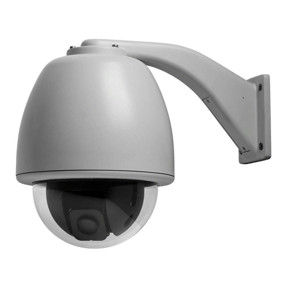
- Page 49 CyberDome Series Installation Manual Appendix C: 8-inch Pendant-mount Housing Installation Method 2: Wall Bracket Installation The CyberDome can be mounted using the KTA-02-12 Wall Bracket, which supports the dome and provides a path for the video, 24VAC, and RS422 control cables. The wall bracket is...
- Page 50 Appendix C: 8-inch Pendant-mount Housing Installation CyberDome Series Installation Manual Step 7) Remove the three hex nuts that hold the pendant housing to the mounting flange. When installing the pendant housing with the W option, remove the triangular stiffener plate (see Figure 71).
- Page 51 CyberDome Series Installation Manual Appendix C: 8-inch Pendant-mount Housing Installation Step 10) Insert the interconnect cable into the RJ45 jack in the upper housing (as shown in Figure 73). Figure 73: Inserting the Interconnect Cable CAUTION! If the power and RS422 cables are reversed in step 11 (below), the CyberDome will be damaged.
-
Page 52: Contacting Technical Support
Many GE Security documents are provided as PDFs (portable document format). To read these documents, you will need Adobe Acrobat Reader, which can be downloaded free from Adobe’s website at www.adobe.com.