Toshiba VF-S15 Instruction Manual
For 3-phase induction motors
Hide thumbs
Also See for VF-S15:
- Instruction manual (394 pages) ,
- Quick start manual (90 pages) ,
- Function manual (80 pages)
Table of Contents
Phone: 800.894.0412 - Fax: 888.723.4773 - Web: www.ctiautomation.net - Email: [email protected]
Industrial Inverter
(For 3-phase induction motors)
Instruction Manual
3-phase 240V class 0.4 to 15kW
1-phase 240V class 0.2 to 2.2kW
3-phase 500V class 0.4 to 15kW
1. Make sure that this instruction manual is delivered to the end
user of the inverter unit.
2. Read this manual before installing or operating the inverter
unit, and store it in a safe place for reference.
WEB version: Revision 0a
NOTICE
E6581611
Safety
I
precautions
Contents
1
Read rst
2
Connection
3
Operations
Setting
4
parameters
Main
5
parameters
Other
6
parameters
Operation
7
with external
signal
Monitoring the
8
operation status
Measures
9
to satisfy the
standards
Peripheral
10
devices
Table of
11
parameters
and data
12
Speci cations
Before making
13
a service call
Inspection and
14
maintenance
15
Warranty
Disposal of the
16
inverter
Table of Contents

Related Manuals for Toshiba VF-S15


Summary of Contents for Toshiba VF-S15
-
Page 1: Industrial Inverter
WEB version: Revision 0a E6581611 Safety precautions Contents Industrial Inverter Read rst (For 3-phase induction motors) Connection Operations Instruction Manual Setting parameters Main parameters Other parameters Operation with externalsignal Monitoring the operation status Measures to satisfy the standards 3-phase 240V class 0.4 to 15kW Peripheral... - Page 2 E6581611 Safety precautions The items described in these instructions and on the inverter itself are very important so that you can use safely the inverter, prevent injury to yourself and other people around you as well as to prevent damage to property in the area.
-
Page 3: Safety Precautions
If the inverter begins to emit smoke or an unusual odor, or unusual sounds, immediately turn the power off. Continuous use of the inverter in such a state will cause fire. Call your Toshiba distributor Mandatory for repairs. -
Page 4: Instruction Manual 4
Do not install or operate the inverter if it is damaged or any component is missing. 1.4.4 This can result in electric shock or fire. Call your Toshiba distributor for repairs. Do not place any inflammable objects near the inverter. -
Page 5: Main
E6581611 Reference Caution section When removing and installing the terminal cover with a screwdriver, be sure not to scratch 1.3.2 your hand as these results in injury. Pressing too hard on the screwdriver can scratch the inverter. 1.3.2 ... -
Page 6: Measures
E6581611 Reference Warning section Ground must be connected securely. If the ground is not securely connected, it could lead to electric shock or fire. Be Grounded Reference Caution section Do not attach devices with built-in capacitors (such as noise filters or surge absorbers) to the output (motor side) terminals. - Page 7 E6581611 Reference Caution section Use an inverter that conforms to the specifications of power supply and three-phase 1.4.1 induction motor being operated. If the inverter being used does not conform to those specifications, not only will the three-phase induction motor not rotate correctly, but it will cause serious accidents through overheating and fire.
-
Page 8: Maintenance And Inspection
Do not replace parts. 14.2 This could be a cause of electric shock, fire and bodily injury. To replace parts, call your Toshiba distributor. Prohibited The equipment must be inspected daily. If the equipment is not inspected and maintained, errors and malfunctions can not be discovered and that could result in accidents. -
Page 9: Table Of Contents
Description of terminals ............................. B-6 3. Operations ..................................C-1 How to Set the Setup Menu ..........................C-2 Simplified Operation of the VF-S15 ........................C-4 How to operate the VF- S15 ..........................C-8 4. Setting parameters ................................ D-1 Setting and Display Modes ..........................D-1 How to set parameters ............................ - Page 10 E6581611 Manual torque boost - increasing torque boost at low speeds ................F-24 Signal output ..............................F-25 Input signal selection ............................F-28 Terminal function selection ..........................F-31 Basic parameters 2 ............................F-33 V/f 5-point setting ...............................F-35 6.10 Frequency priority selection ..........................F-35 6.11 Operation frequency ............................F-44 6.12 DC braking .................................F-46 6.13...
- Page 11 E6581611 8. Monitoring the operation status ............................. H-1 Flow of status monitor mode ..........................H-1 Status monitor mode ............................H-2 Display of trip information ..........................H-6 9. Measures to satisfy the standards ..........................I-1 How to cope with the CE Marking Directive ....................... I-1 Compliance with UL Standard and CSA Standard .....................
- Page 12 E6581611 15. Warranty ..................................O-1 16. Disposal of the inverter ..............................P-1 Phone: 800.894.0412 - Fax: 888.723.4773 - Web: www.ctiautomation.net - Email: [email protected]...
-
Page 13: Read First
E6581611 1. Read first Check product purchase Before using the product you have purchased, check to make sure that it is exactly what you ordered. Caution Use an inverter that conforms to the specifications of power supply and three-phase induction motor being used. -
Page 14: Contents Of The Product
W: W orl d m odel 002 : 0.2kW TOSVERT 2 : 200V to 240V EMC filter None: Japanese model VF-S15 series 004 : 0.4kW 4 : 380V to 500V M: Built-in basic filter 007 : 0.75kW 015 : 1.5kW 022 : 2.2kW... -
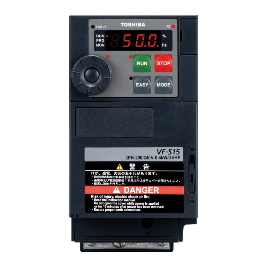
Page 15: Names And Functions
E6581611 Names and functions 1.3.1 Outside view Charge lamp Indicates there is a high voltage still in the inverter. STATUS lamp Do not open the terminal block cover when this lamp is lit because it is dangerous. Lights and blinks when ®... - Page 16 E6581611 Example of the protective label on the top of the inverter [Opening the cover] Insert a small screw driver and slide the door lock to upside for unlock. (Slide it to downside for lock.) About the monitor display The LED on the operation panel uses the following symbols to indicate parameters and operations. LED display (numbers) LED display (letters) Phone: 800.894.0412 - Fax: 888.723.4773 - Web: www.ctiautomation.net - Email: [email protected]...
- Page 17 E6581611 [Operation panel] % lamp RUN lamp Hz lamp Lit when a frequency is Displayed numbers are Displayed numbers are not output with the ON in Hertz. in %. run command. This lamp blinks when operation RUN key starts. Pressing this key while the RUN key lamp is on PRG lamp starts operation.
- Page 18 E6581611 1.3.2 Opening terminal cover and terminal block Warning Never touch the internal connector while the upper cover of control panel is opened. There is a risk of electrical shock because it carries a high voltage. Prohibited Caution When removing and mounting the terminal cover or the terminal block with a screwdriver, be sure not to scratch your hand as these results in injury.
- Page 19 E6581611 (1) Removing the outside terminal block cover (VFS15-2004PM-W to 2007PM-W, VFS15S-2002PL-W to 2007PL-W) Press in on the screwdriver. Insert a screwdriver or other thin object into the hole indicated with the mark. Pull the terminal cover up at an angle. While pressing on the screwdriver, rotate the terminal cover downward to remove it.
- Page 20 E6581611 (2) Removing the inside terminal block cover (VFS15-2004PM-W to 2007PM-W, VFS15S-2002PL-W to 2007PL-W) The finger is put on to the tab part of the While pressing on the screwdriver, rotate the terminal block cover. terminal cover downward to remove it. Pull the terminal cover up at an angle.
- Page 21 E6581611 (3) Removing the outside terminal block cover (VFS15-2015PM-W to 2037PM-W, VFS15S-2015PL-W, 2022PL-W, VFS15-4004PL-W to 4037PL-W) Insert a screwdriver or other thin object into the Press in on the screwdriver. hole indicated with the mark. While pressing on the screwdriver, sidles the terminal cover downward to remove it.
- Page 22 E6581611 (4) Removing the inside terminal block cover (VFS15-2015PM-W to 2037PM-W, VFS15S-2015PL-W, 2022PL-W, VFS15-4004PL-W to 4015PL-W) The finger is put on to the tab part of the While pressing on the screwdriver, rotate the terminal block cover. terminal cover downward to remove it. Pull the terminal cover up at an angle.
- Page 23 E6581611 (5) Removing the inside terminal block cover (VFS15-4022PL-W, 4037PL-W) The finger is put on to the tab part of the While pressing on the screwdriver, rotate the terminal block cover. terminal cover downward to remove it. Pull the terminal cover up at an angle. ●...
- Page 24 E6581611 (6) Removing the power terminal cover (VFS15-2055PM-W to 2150PM-W, VFS15-4055PL-W to 4150PL-W) Insert a screwdriver or other thin object into the Press in on the screwdriver. hole indicated with the mark. While pressing on the screwdriver, slide the ● After wiring is complete, be sure to restore the terminal cover downward to remove it.
- Page 25 E6581611 1.3.3 Power circuit and control circuit terminal blocks 1) Power circuit terminal In case of the lug connector, cover the lug connector with insulated tube, or use the insulated lug connector. (Recommended Lug connectors and Insulated Tubes) Manufacturer and Type-Form Wire Size Screw Size Lug connector...
- Page 26 E6581611 VFS15-2004PM-W to 2007PM-W M3.5 screw Shorting-bar Grounding terminal Grounding terminal (M4 screw) (M4 screw) Grounding terminal For EMC plate (M5 screw) Note1) Bend the clips on the wiring port of the terminal cover to connect the PB, PO, PA/+, and PC/- terminals. Note2) Be careful to insert all wires into the cage of terminal block.
- Page 27 E6581611 VFS15-2015PM-W, 2022PM-W M4 screw Shorting-bar Grounding terminal Grounding terminal (M4 screw) (M4 screw) Grounding terminal For EMC plate (M5 screw) VFS15-2037PM-W M4 screw Shorting-bar Grounding terminal For EMC plate (M5 screw) Note1) Bend the clips on the wiring port of the terminal cover to connect the PB, PO, PA/+, and PC/- terminals. Note2) Be careful to insert all wires into the cage of terminal block.
- Page 28 E6581611 VFS15S-2002PL-W to 2007PL-W Grounding capacitor switch Shorting-bar Grounding terminal Grounding terminal (M4 screw) (M4 screw) Grounding terminal (M5 screw) For EMC plate VFS15S-2015PL-W, 2022PL-W M4 screw Grounding capacitor switch Shorting-bar Grounding terminal Grounding terminal (M4 screw) (M4 screw) Grounding terminal (M5 screw) For EMC plate Note1) Bend the clips on the wiring port of the terminal cover to connect the PB, PO, PA/+, and PC/- terminals.
- Page 29 E6581611 VFS15-4004PL-W to 4015PL-W Shorting-bar Grounding capacitor switch M4 screw Grounding terminal (M5 screw) For EMC plate VFS15-4022PL-W, 4037PL-W Grounding capacitor switch M4 screw Shorting-bar Grounding terminal (M5 screw) For EMC plate Note1) Bend the clips on the wiring port of the terminal cover to connect the PB, PO, PA/+, and PC/- terminals. Note2) Be careful to insert all wires into the cage of terminal block.
- Page 30 E6581611 VFS15-2055PM-W, 2075PM-W VFS15-4055PL-W, 4075PL-W Grounding capacitor switch (4055PL-W, 4075PL-W only) M5 screw Shorting-bar Grounding terminal (M5 screw) Grounding terminal (M5 screw) For EMC plate VFS15-2110PM-W, 2150PM-W M6 screw Shorting-bar Grounding terminal Grounding terminal (M5 screw) (M5 screw) For EMC plate Note1) Bend the clips on the wiring port of the terminal cover to connect the PB, PO, PA/+, and PC/- terminals.
- Page 31 E6581611 VFS15-4110PL-W, 4150PL-W Grounding capacitor switch M5 screw Shorting-bar Grounding terminal (M5 screw) Grounding terminal (M5 screw) For EMC plate Note1) Bend the clips on the wiring port of the terminal cover to connect the PB, PO, PA/+, and PC/- terminals. Note2) Be careful to insert all wires into the cage of terminal block.
- Page 32 E6581611 2) Grounding capacitor switch Single-phase 240V model and three-phase 500V model have a built-in high-attenuation noise filter and is grounded via a capacitor. A switch makes for easy switching to reduce leakage current from the inverter and the load on the capacitor.
- Page 33 E6581611 3) Control circuit terminal block The control circuit terminal block is common to all equipment. VIB CC VIC S3 FM FLA FLB FLC RY RC SINK SOURCE OUT P24 F R CC +SU +24 Screw for removable control terminal block RES S1 S2 RS485 connector Recommended...
-
Page 34: Notes On The Application
E6581611 Notes on the application 1.4.1 Motors When this inverter and the motor are used in conjunction, pay attention to the following items. Caution Use an inverter that conforms to the specifications of power supply and three-phase induction motor being operated. If the inverter being used does not conform to those specifications, not only will the three-phase induction motor not rotate correctly, but it will cause serious accidents through overheating Mandatory and fire. - Page 35 E6581611 Low loads and low inertia loads The motor may demonstrate instability such as abnormal vibrations or overcurrent trips at light loads of 50% or under of the load percentage, or when the load's inertia moment is extremely small. If that happens reduce the carrier frequency.
- Page 36 E6581611 Motors with a brake When motors with a brake are directly connected to the inverter's output, the brake cannot be released at startup because of low voltage. Wire the brake circuit separately from the main circuit. 3-phase FLB FLC S2 (ST) power source Circuit diagram 1...
- Page 37 E6581611 1.4.2 Inverters Protecting inverters from overcurrent The inverter has an overcurrent protection function. The programmed current level is set to the inverter's maximum applicable motor. If the motor used has a small capacity, the overcurrent level and the electronic thermal protection must be readjusted. If adjustment is necessary, refer to section 5.6, and make adjustments as directed.
- Page 38 E6581611 Circuit breaking when two or more inverters are used on the same power line MCCB1 MCCB2 (circuit breaking fuse) INV1 MCCB3 INV2 MCCB: Molded-case MCCBn 1 circuit breaker INVn Breaking of selected inverter There is no fuse in the inverter's main circuit. Thus, as the diagram above shows, when more than one inverter is used on the same power line, you must select interrupting characteristics so that only MCCB2 to MCCBn+1 will trip and the MCCB1 will not trip when a short occurs in the inverter (INV1).
- Page 39 E6581611 1.4.3 What to do about the leakage current Caution The leakage current through the input/output power cables of inverter and capacitance of motor can affect to peripheral devices. The value of leakage current is increased under the condition of the PWM carrier frequency and the Mandatory length of the input/output power cables.
- Page 40 E6581611 (2) Influence of leakage current across lines Thermal relays Inverter Power supply Leakage current path across wires Thermal relays The high frequency component of current leaking into electrostatic capacity between inverter out- put wires will increase the effective current values and make externally connected thermal relays operate improperly.
-
Page 41: Installation Environment
E6581611 motor's magnetic noise. The setting of PWM carrier frequency is done with the parameter f300 (Refer to section 6.18). Remedies: 1. Use a meter output terminal in the inverter control circuit. The load current can be output on the meter output terminal (FM). If the meter is connected, use an ammeter of 1mAdc full scale or a voltmeter of 10V full scale. - Page 42 If the inverter is installed in a location that is subject to vibration, anti-vibration measures are required. Please consult with Toshiba about these measures. If the inverter is installed near any of the equipment listed below, provide measures to insure against errors in operation.
- Page 43 Warning Do not install or operate the inverter if it is damaged or any component is missing. This can result in electric shock or fire. Call your Toshiba distributor for repairs. Prohibited Mount the inverter on a metal plate.
- Page 44 E6581611 The space shown in the diagram is the minimum allowable space. Because air cooled equipment has cooling fans built in on the top or bottom surfaces, make the space on top and bottom as large as possible to allow for air passage.
- Page 45 E6581611 Panel designing taking into consideration the effects of noise The inverter generates high frequency noise. When designing the control panel setup, consideration must be given to that noise. Examples of measures are given below. Wire so that the main circuit wires and the control circuit wires are separated. Do not place them in the same conduit, do not run them parallel, and do not bundle them.
- Page 46 E6581611 Installing more than one unit in a cabinet When two or more inverters are installed in one cabinet, pay attention to the followings. Inverters may be installed side by side with each other with no space left between them. When installing inverters side by side, remove the protective label on the top of the inverter.
-
Page 47: Connection
2. Connection Warning Never disassemble, modify or repair. This can result in electric shock, fire and injury. Call your Toshiba distributor for repairs. Disassembly prohibited Do not stick your fingers into openings such as cable wiring holes and cooling fan covers. - Page 48 E6581611 Warning Ground must be connected securely. If the ground is not securely connected, it could lead to electric shock or fire. Be Grounded Caution Do not attach devices with built-in capacitors (such as noise filters or surge absorber) to the output (motor side) terminal.
-
Page 49: Standard Connections
E6581611 Standard connections Warning Do not connect input power to the output (motor side) terminals (U/T1, V/T2, W/T3). Connecting input power to the output could destroy the inverter or cause a fire. Do not insert a braking resistor between DC terminals (between PA/+ and PC/- or PO and PC/-). It could cause a fire. -
Page 50: Standard Connection Diagram
W/T3 -50/60Hz Control power supply Forward run command Single MCCB(2P) Control phase R/L1 Reverse run command VF-S15 circuit Power S/L2/N Reset supply Preset-speed command 1 Preset-speed command 2 Protective function activation output Preset-speed command 3 *1: The T/L3 terminal is not provided for... - Page 51 T/L3 W/T3 3ph-500V class: three-phase 380-500V -50/60Hz Control power MCCB(2P) supply Single Forward run command R/L1 phase Control VF-S15 Power circuit S/L2/N Reverse run command supply Reset Preset-speed command 1 Protective function Preset-speed command 2 activation output Preset-speed command 3...
-
Page 52: Description Of Terminals
E6581611 Description of terminals 2.3.1 Power circuit terminals Connections with peripheral equipment Molded-case Magnetic Input AC noise contactor circuit braker reactor reduction filter Motor Inverter U/T1 R/L1 Power S/L2 V/T2 supply W/T3 T/L3 Zero-phase PA/+ reactor Braking resistor Note 1: The T/L3 terminal is not provided for any single-phase models. So if you are using single-phase models, use the R/L1 and S/L2/N terminals to connect power cables. - Page 53 E6581611 2.3.2 Control circuit terminals The control circuit terminal block is common to all equipment. Regarding to the function and specification of each terminal, please refer to the following table. Refer to section 1.3.3.3) about the arrangement of control circuit terminals. ...
- Page 54 E6581611 Terminal Input / Electrical Function Inverter internal circuits symbol output specifications Common Control circuit's equipotential terminal to Input / (3 terminals) output +24V 10Vdc Voltage Output Analog power supply output (permissible load Regulator current: 10mAdc) Multifunction programmable analog input. Default setting: 0-10Vdc (1/1000 resolution) and 0-60Hz (0-50Hz) 10Vdc...
- Page 55 E6581611 Terminal Input / Electrical Function Inverter internal circuits symbol output specifications 1mAdc full-scale ammeter or QS60T(option) Multifunction programmable analog 0-20mA (4-20mA) +24V – output. Default setting: output frequency. DC ammeter The function can be changed to meter Permissible load +24V Voltage Output...
- Page 56 E6581611 Terminal Input / Electrical Function Inverter internal circuits symbol output specifications Multifunction programmable open Open collector collector output. Default setting detect output and output speed reach signal. 24Vdc-100mA Multifunction output terminals to which two different functions can be assigned. To output pulse The NO terminal is an equipotential trains,...
- Page 57 E6581611 Connection of SINK (Negative) logic/SOURCE (Positive) logic (When the inverter's internal power supply is used) Current flowing out turns control input terminals on. These are called sink logic terminals. The general used method in Europe is source logic in which current flowing into the input terminal turns it Sink logic is sometimes referred to as negative logic, and source logic is referred to as positive logic.
-
Page 58
E6581611 SINK (Negative)/ SOURCE (Positive) logic connection (When an external power supply is used) The P24 terminal is used to connect to an external power supply or to separate a terminal from other input or output terminals.
Slide switch SW1 : PLC side Slide switch SW1 : PLC side Source (Positive) logic... - Page 59 E6581611 Switching of slide switch Refer to section 1.3.3 3) about location of slide switch. (1) Switching of sink/source logic: SW1 (Default setting : PLC side) Setting of sink/source logic for F, R, RES, S1, S2, and S3 terminals are switched by slide switch SW1. When an external power supply is used for sink logic, set the slide switch SW1 to PLC side.
-
Page 60: Operations
Continuous use of the inverter in such a state will cause fire. Call your Toshiba distributor for repairs. Always turn the power off if the inverter is not used for long periods of time since there is a possibility of malfunction caused by leaks, dust and other material. -
Page 61: How To Set The Setup Menu
Toshiba distributer.) Each setup menu automatically sets all parameters relating to the base frequency and the base frequency voltage of the motor connected. - Page 62 E6581611 Values set by each setup parameter asia (Mainly in Asia, Title Function (Mainly in (Mainly in (Mainly in Oceania) Europe) North America) Japan) Note 1) ul/vl/170/ f204 /f213 / 50.0(Hz) 60.0(Hz) 50.0(Hz) Frequency 60.0(Hz) f219 /f330 / f367 /f814 240V Base...
-
Page 63: Simplified Operation Of The Vf-S15
E6581611 Simplified Operation of the VF-S15 Operation command and Operation frequency command are necessary to operate the inverter. Operation method and operation frequency setting can be selected from the following. At default setting, the inverter runs and stops with RUN/STOP key on the panel keypad, and frequency can be set with the setting dial. - Page 64 E6581611 3.2.1 How to run and stop [Example of setting procedure] Panel operation LED display Operation Displays the output frequency (operation stopped). (When standard monitor display selection f710=0 [output frequency]) MODE Displays the first basic parameter [History (auh)]. cmod Turn the setting dial, and select "cmod".
- Page 65 E6581611 (3) Coast stop Coast stop Assign parameters as described below in case of Motor Coast stop. Inverter will display off at Coast stop. speed 1) Assign "6 (ST)" to an input terminal. Set parameter =. Open the ST-CC for coast stop(see the F-CC status described on the right).
- Page 66 E6581611 3.2.2 How to set the frequency [Example of fmod setting procedure] fmod=1: Setting the frequency by the terminal VIA Panel operation LED display Operation Displays the output frequency (operation stopped). 00 (When standard monitor display selection f710=0 [output frequency]) MODE Displays the first basic parameter [History (auh)].
-
Page 67: How To Operate The Vf-S15
E6581611 How to operate the VF-S15 Overview of how to operate the inverter with simple examples Operation Command: Panel Operation Ex.1 Frequency Command: Setting Dial 1 Wiring PC/- PA/+ Motor MCCB U/T1 R/L1 S/L2 V/T2 W/T3 T/L3 Operation panel Parameter setting (default setting) - Page 68 E6581611 Operation Command : Panel Operation Ex.2 Frequency Command: Setting Dial 2 Wiring PA/+ PC/- Motor MCCB R/L1 U/T1 S/L2 V/T2 T/L3 W/T3 Operation panel Parameter setting Title Function Setting value Command mode selection Frequency setting mode selection 1 Operation STOP Run/stop: Press the...
- Page 69 E6581611 Operation Command: External Signal Ex.3 Frequency Command: Setting Dial Wiring PA/+ PC/- Motor MCCB R/L1 U/T1 S/L2 V/T2 W/T3 T/L3 Forward signal Operation panel Reverse signal Common Parameter setting Title Function Setting value Command mode selection 0 or 3 ...
- Page 70 E6581611 Operation Command: External Signal Ex.4 Frequency Command: External Analog Signal Wiring PC/- PA/+ Motor MCCB R/L1 U/T1 S/L2 V/T2 T/L3 W/T3 Forward signal Reverse signal Common Current signal: VIB PP 4(0)20mA Voltage signal: 0+10V (or -10+10Vdc) External potentiometer (Otherwise, input voltage signal between the terminals VIA-CC.) Parameter setting Title Function...
-
Page 71: Setting Parameters
E6581611 4. Setting parameters Setting and Display Modes This inverter has the following three display modes. Standard monitor mode The standard inverter mode. This mode is enabled when inverter power goes on. This mode is for monitoring the output frequency and setting the frequency reference value. If also displays information about status alarms during running and trips. - Page 72 E6581611 Status monitor mode The mode for monitoring all inverter status. Allows monitoring of frequency command value, output current/voltage and terminal information. Refer to chapter 8. The inverter can be moved through each of the modes by pressing the MODE key. ...
-
Page 73: How To Set Parameters
E6581611 How to set parameters There are two types of setting monitor modes: Easy mode and Standard setting mode. The mode active when power is turned on can be selected at (EASY key mode selection), and the mode can be switched by the EASY key. Note, however, that the switching method differs when only the Easy mode is selected. - Page 74 E6581611 Standard setting mode : The mode changes to the Standard setting mode when the EASY key is pressed and "std" is displayed. Both basic and extended all parameters are displayed. Basic parameters : This parameter is a basic parameter for the operation of the inverter.
- Page 75 E6581611 4.2.1 Settings in the Easy setting mode The inverter enters this mode by pressing the MODE key when the Easy setting mode is selected Easy setting mode (Registered parameters at default setting) When you are unsure of something during operation: Title Function You can return to the Standard monitor...
- Page 76 E6581611 4.2.2 Settings in the Standard setting mode The inverter enters this mode by pressing the MODE key when the Standard setting mode is selected. How to set basic parameters When you are unsure of something (1) Select parameter to be changed. (Turn the setting dial.) during operation: You can return to the Standard monitor (2) Read the programmed parameter setting.
-
Page 77: Functions Useful In Searching For A Parameter Or Changing A Parameter Setting
E6581611 How to set extended parameters Each extended parameter is composed of an "f, a or c "suffixed with a 3-digit figure, so first select and read out the heading of the parameter you want "f1" to "f9", "a", "c" ("f1": Parameter starting point is 100, "a": Parameter starting point is A.) (5) Select the title of the parameter you want to change. - Page 78 E6581611 Set parameters by purpose (Guidance function) auf Only parameters required for a special purpose can be called up and set. To use this function, select parameter auf Refer to section 6.1.3 for details. Reset parameters to default settings typ Use the typ parameter to reset all parameters back to the default settings.
- Page 79 E6581611 How to search and reprogram parameters Panel operation LED display Operation Displays the output frequency (operation stopped). (When standard monitor display selection is set as f710=0 00 [output frequency]) MODE Displays the first basic parameter "History function (auh)." Turn the setting dial, and select gru.
- Page 80 E6581611 4.3.2 Return to default settings typ : Default setting Function It is possible to return groups of parameters to their defaults, clear run times, and record/recall set parameters. [Parameter setting] Title Function Adjustment range Default setting 0: - 1: 50Hz default setting 2: 60Hz default setting 3: Default setting 1 (Initialization)
- Page 81 Initialization of type information (typ = 6) Setting typ to 6 clears the trips when an etyp format error occurs. But if the displayed, contact your Toshiba distributor. D-11 Phone: 800.894.0412 - Fax: 888.723.4773 - Web: www.ctiautomation.net - Email: [email protected]...
- Page 82 E6581611 Save user setting parameters (typ = 7) Setting typ to 7 saves the current settings of all parameters. Load user setting parameters (typ = 8) Setting typ to 8 loads parameter settings to (calls up) those saved by setting typ to 7. * By setting typ to 7 or 8, you can use parameters as your own default parameters.
-
Page 83: Checking The Region Settings Selection
E6581611 Checking the region settings selection set : Checking the region setting Function The region selected on the setup menu can be checked. Also, the setup menu starts and can be changed to a different region. [Parameter setting] Title Function Adjustment range Default setting... -
Page 84: Easy Key Function
E6581611 EASY key function psel : EASY key mode selection f750 : EASY key function selection f751 to f782 : Easy setting mode parameter 1 to 32 Function It is possible to switch between standard mode and easy setting mode using the EASY key. (default setting) Up to 32 arbitrary parameters can be registered to easy setting mode. - Page 85 E6581611 psel =0 * When the power is turned on, the inverter is in standard mode. Press the EASY key to switch to easy setting mode. psel =1 * When the power is turned on, the inverter is in easy setting mode. Press the EASY key to switch to standard mode.
- Page 86 E6581611 [How to select parameters] Select the desired parameters as easy setting mode parameters 1 to 32 (f751 to f782). Note that parameters should be specified by communication number. For communication numbers, refer to Table of parameters. In easy setting mode, only parameters registered to parameters 1 to 32 are displayed in order of registration. The values of the default settings are shown in the table below.
- Page 87 E6581611 Shortcut key function (f750=1) This function allows you to register, in a shortcut list, parameters whose settings need to be changed frequently so that you can read them out easily in a single operation. The shortcut is usable in the frequency monitor mode only. [Operation] Set f750 to 1, read out the setting of the parameter you want to register, and press and hold down the EASY key for 2 seconds or more.
-
Page 88: Main Parameters
E6581611 5. Main parameters Here are described main parameters you set before use according to the section 11. Tables of parameters and data. Meter setting and adjustment : Meter selection : Meter adjustment gain Function Output of 0 - 1mAdc, 0 (4) - 20mAdc, 0 - 10vdc can be selected for the output signal from the FM terminal, depending on the ... -
Page 89
E6581611 Adjustment scale with parameter (Meter adjustment) Connect meters as shown below.
= = Inverter Inverter The reading of the The reading of the meter will fluctuate meter will during scale fluctuate during * Optional QS-60T frequency * Meter with a maximum... - Page 90 E6581611 Example of 4-20mA output adjustment (Refer to section 6.33.3 for details) =1, =0 =1, =20 (mA) (mA) Output Output currrent currrent f692 100% 100% Internal calculated value Internal calculated value Note 1) When using the FM terminal for current output, be sure that the external load resistance is less than 600Ω. Use over 1kΩ...
-
Page 91: Setting Acceleration/Deceleration Time
E6581611 Setting acceleration/deceleration time : Acceleration time 1 : Setting of acceleration/deceleration time unit : Deceleration time 1 : Automatic acceleration/deceleration Function 1) For acceleration time 1 programs the time that it takes for the inverter output frequency to go from 0.0Hz to maximum frequency . -
Page 92: Maximum Frequency
E6581611 Maximum frequency : Maximum frequency Function 1) Programs the range of frequencies output by the inverter (maximum output values). 2) This frequency is used as the reference for acceleration/deceleration time. Output frequency When =80Hz ・This function determines the value (Hz) 80Hz in line with the ratings of the motor... -
Page 93: Upper Limit And Lower Limit Frequencies
E6581611 Upper limit and lower limit frequencies : Upper limit frequency : Lower limit frequency Function Programs the lower limit frequency that determines the lower limit of the output frequency and the upper limit frequency that determines the upper limit of that frequency. Lower limit Upper limit Command frequency (Hz) -
Page 94: Base Frequency
E6581611 Base frequency : Base frequency 1 : Base frequency voltage 1 Function Set the base frequency and the base frequency voltage in conformance with load specifications or the base frequency. Note: This is an important parameter that determines the constant torque control area. Base frequency voltage ... -
Page 95: Setting The Electronic Thermal
E6581611 Setting the electronic thermal : Overload characteristic selection : Motor electronic-thermal protection level 1 : Electronic-thermal protection characteristic selection 3 : Motor electronic-thermal protection level 2 : Motor 150% overload detection time ... - Page 96 E6581611 [Parameter setting] Title Function Adjustment range Default setting 0: Disabled (thr, f173) 1: Enabled (thr, f173) Electronic-thermal memory 2: Disabled (thr) 3: Enabled (thr) 10-100 Overload alarm level *1: The inverter's rated current is 100%. When (current/voltage unit selection) = 1 (A (amps)/V (volts)) is selected, it can be set at A (amps).
- Page 97 E6581611 Setting of electronic thermal protection characteristics selection Setting value Overload protection Overload stall valid invalid valid valid invalid invalid invalid valid Setting of motor electronic thermal protection level 1 thr (Same as f173) When the capacity of the motor in use is smaller than the capacity of the inverter, or the rated current of the motor is smaller than the rated current of the inverter, adjust thermal protection level 1 thr for the motor in accordance with the motor's rated current.
- Page 98 E6581611 [Using a VF motor (motor for use with inverter)] Setting of electronic thermal protection characteristics selection Setting value Overload protection Overload stall valid invalid valid valid invalid invalid invalid valid VF motors (motors designed for use with inverters) can be used in frequency ranges lower than those for standard motors, but their cooling efficiency decreases at frequencies below 6Hz.
- Page 99 E6581611 = (150%-60s), = (Constant torque characteristic) Protection is given uniformly regardless of temperature, as shown by the 150%-60 sec overload curve in the figure below. Inverter overload Current Inverter overload time [s] time [s] (Outline data) 2400 Monitored output current [%] 110% 150% 100%: Inverter rated output current...
- Page 100 E6581611 Note 1: If the load applied to the inverter 150% or more of its rated load or the operation frequency is 0.1Hz or less, the inverter may trip (ol1 or oc1 to oc3) in a shorter time. Note 2: The inverter is default setting so that, if the inverter becomes overloaded, it will automatically reduce the carrier frequency to avoid an overload trip (ol1 or oc1 to oc3).
- Page 101 E6581611 5) Overload characteristic selection aul Overload characteristic of inverter can be selected to 150%-60s or 120%-60s. [Parameters settings] Title Function Adjustment range Default setting 0: - 1: Constant torque Overload characteristic selection characteristic(150%-60s) 2: Variable torque characteristic(120%-60s) ● Regarding to characteristic for aul=1 setting, refer to section 5.6.3). Note 1) In case of aul=2 setting, be sure to install the input AC reactor (ACL) between power supply and inverter.
- Page 102 E6581611 = (Variable torque characteristic), = (Temperature estimation) This parameter adjusts automatically overload protection, predicting the inverter internal temperature rise. (diagonally shaded area in the figure below) time [s] f631=0 Monitored output current [%] 105% 120% 100%: Inverter rated output current Note 1: The rated output current of inverter is changed by setting of aul=1 or 2.
-
Page 103: Preset-Speed Operation (Speeds In 15 Steps
E6581611 Preset-speed operation (speeds in 15 steps) sr0 to sr7 : Preset-speed frequency 0 to 7 f287 to f294 : Preset-speed frequency 8 to15 f724 : Operation frequency setting target by setting dial Function A maximum of 15 speed steps can be selected just by switching an external logic signal. Multi-speed frequencies can be programmed anywhere from the lower limit frequency ... - Page 104 E6581611 Note) When the other preset-speed command is input while adjusting frequency with the setting dial, operation frequency will change but not the inverter display and the subject of adjustment. Ex) If sr2 is input when operating under sr1 and changing frequency with the setting dial, operation frequency will change to sr2 but inverter display and the subject of adjustment continue to be sr1.
- Page 105 E6581611 3) Using other speed commands with preset-speed command 1: Panel keypad (including extension panel) Command mode 2: RS485 communication 0: Terminal block selection 3: CANopen communication 4: Communication option 0:Setting dial 1 (including extension 0:Setting dial 1 (including extension panel) panel) (save even if power is off) (save even if power is off) 1: Terminal VIA...
-
Page 106: Switching Between Two Frequency Commands
E6581611 Switching between two frequency commands fmod : Frequency setting mode selection1 f200 : Frequency priority selection f207 : Frequency setting mode selection2 Function These parameters are used to switch between two frequency commands automatically or with input terminal signals. Parameter setting Title Function... - Page 107 E6581611 2) Automatic switching by frequency command Frequency priority selection parameter f200 = 1 Switch frequency command set with fmod and f207 automatically according to the frequency command entered. If the frequency set with fmod is above 1Hz: The frequency command set with fmod If the frequency set with fmod is 1Hz or less: The frequency command set with f207 E-20 Phone: 800.894.0412 - Fax: 888.723.4773 - Web: www.ctiautomation.net - Email: [email protected]...
-
Page 108: Auto-Restart (Restart Of Coasting Motor
E6581611 Auto-restart (Restart of coasting motor) f301 : Auto-restart control selection Caution Stand clear of motors and mechanical equipment If the motor stops due to a momentary power failure, the equipment will start suddenly when power is restored. Mandatory This could result in unexpected injury. - Page 109 E6581611 2) Restarting motor during coasting (Motor speed search function) Motor speed Forward / reverse ST-CC ● Setting f301 to 2 o r 3: This function operates after the ST-CC terminal connection has been opened first and then connected again. Note 1: As the default setting for ST (Standby) is Always ON, change the following settings.
-
Page 110: Changing Operation Panel Display
E6581611 5.10 Changing operation panel display 5.10.1 Changing the unit (A/V) from a percentage of current and voltage f701 :Current/voltage unit selection Function These parameters are used to change the unit of monitor display. % A (ampere)/V (volt) Current 100% = Rated current of inverter Voltage 100% = 200Vac (240V class), 400Vac (500V class) ... - Page 111 E6581611 5.10.2 Displaying the motor or the line speed f702 : Frequency free unit display magnification f703 : Frequency free unit coverage selection f705 : Inclination characteristic of free unit display f706 : Free unit display bias Function The frequency or any other item displayed on the monitor can be converted into the rotational speed of the motor or load device.
- Page 112 E6581611 * The f702 converts the following parameter settings: In case of f703=0 Free unit Frequency monitor display Output frequency, Frequency command value, PID feedback value, Stator frequency, During stop: Frequency command value (During operation: Output frequency) fc, fh, ul, ll, sr0 sr7, Frequency-related parameters f100, f101, f102, f167, f190, f192, f194, f196, f198, f202, f204, f211,...
-
Page 113: Other Parameters
E6581611 6. Other parameters Extended parameters are provided for sophisticated operation, fine adjustment and other special purposes. Modify parameter settings as required. Refer to section 11. tables of parameters. Refer to the corresponding sections regarding the following parameters. Title Function Reference Overload characteristic selection 5.6, 6.18... -
Page 114: Parameters Useful For Setting And Adjustments
E6581611 Parameters useful for settings and adjustments 6.1.1 Searching for changes using the history function (auh) auh : History function History function (auh): Automatically searches for 5 latest parameters that are programmed with values different from the default setting and displays them in the auh. Parameter setting can also be changed within this group auh. - Page 115 E6581611 Notes on operation If no history information is stored, this parameter is skipped and the next parameter “aua” is displayed. head and end are added respectively to the first and last parameters in a history of changes. Note: The following parameters are not displayed in this auh, even if they are the most recent changes.
- Page 116 E6581611 How to use the Application easy setting Choose the machine Operation panel LED display Operation action Displays the output frequency. 00 (When standard monitor display selection is set to [output frequency]) MODE The first basic parameter “auh” (history function) is displayed. Turn the setting dial to the right to change the parameter to aua.
- Page 117 E6581611 f768 f201 f240 f332 f218 f218 f361 f769 f202 f243 f333 f219 f219 f362 f770 f203 f250 f334 f295 f295 f363 f771 f204 f251 f340 f301 f301 f366 f772 f240 f252 f341 f302 f302 f367 f773 f243 f304 f345 f303 f303 f368...
- Page 118 E6581611 How to use the guidance function Here are the steps to follow to set parameters, using the guidance function. (When the Preset speed guidance auf = 2) Operation panel LED display Operation action Displays the operation frequency (output stopped). (When standard monitor display selection =...
- Page 119 E6581611 Table of parameters that can be changed using the guidance function Preset-speed setting Motor 1&2 switching operation Motor constant setting guidance auf=2 auf=4 auf=5 ...
- Page 120 E6581611 Example in case the acceleration Example in case the acceleration Output Output and deceleration time become short and deceleration time become long frequency (Hz) frequency (Hz) Time Time [sec] [sec] Deceleration Acceleration Acceleration Deceleration time time time time Set ...
-
Page 121: Increasing Starting Torque
E6581611 6.1.5 Increasing starting torque au2 : Torque boost setting macro function Function Simultaneously switches inverter output (V/F) control and programs motor constants automatically (On- line automatic-tuning function) to improve torque generated by the motor. This parameter integrates the selection of function including vector control and setting of auto-tuning. - Page 122 E6581611 2) When using vector control (increasing starting torque and high-precision operations) is set to (Vector control + auto-tuning) Setting torque boost setting macro function control to (vector control + auto-tuning) provides high starting torque bringing out the maximum in motor characteristics from the low-speed range. This suppresses changes in motor speed caused by fluctuations in load to provide high precision operation.
- Page 123 E6581611 If vector control cannot be programmed..First read the precautions about vector control in section 6.3.9). 1) If the desired torque cannot be obtained Refer to section 6.25 selection 2 2) If auto-tuning error "" appears Refer to section 6.25 selection 4 ...
-
Page 124: Selection Of Operation Mode
E6581611 Selection of operation mode 6.2.1 Selection of start/stop and frequency settings cmod : Command mode selection fmod : Frequency setting mode selection Function These parameters are used to specify which input device (panel keypad, terminal block, or communication) takes priority in entering an operation stop command or frequency setting mode (terminal VIA/VIB/VIC, setting dial, communication, or UP/DOWN from external logic). -
Page 125
E6581611
[Parameter setting] Title Function Adjustment range Default setting 0: Setting dial 1 (including extension panel option) (save even if power is off) 1: Terminal VIA 2: Terminal VIB 3: Setting dial 2 (including extension panel option) (press in center to save) 4: RS485 communication ... - Page 126 E6581611 Communication Frequencies are set by commands from a communication option. : Refer to each Instruction Manual of option. option A frequency command is set by means of external analog signals. : Terminal VIC (VIC terminal: 0 (4) - 20mAdc) ...
- Page 127 E6581611 Example of run and frequency command switching Command mode and frequency setting mode switching Command mode selection With extension panel Terminal block RS485 communication (option) RKP007Z active (CMTB) priority clear Input terminal (SCLC) function Input terminal function :48/49 :108/109 Terminal block...
- Page 128 E6581611 6.2.2 Forward/reverse run selection (Panel keypad) fr : Forward/reverse run selection (Panel keypad) Function Program the direction of rotation of the motor when the running and stopping are made using the RUN key and STOP key on the operation panel. Valid when ...
-
Page 129: Selecting Control Mode
E6581611 Selecting control mode pt : V/F control mode selection Function The V/F controls shown below can be selected. V/F constant Variable torque Automatic torque boost control *1 Vector control *1 Energy saving *1 ... - Page 130 E6581611 Steps in setting are as follows (In this example, the V/F control mode selection parameter is set to (Vector control). [Setting V/F control mode selection to 3 (sensorless vector control)] Operation panel LED display Operation action Displays the output frequency. (Perform during operation stopped.) ....
- Page 131 E6581611 1) Constant torque characteristics Setting of V/F control mode selection to (V/F constant) This is applied to loads with equipment like conveyors and cranes that require the same torque at low speeds as at rated speeds. Base frequency voltage ...
- Page 132 ● Motor constant must be set If the motor you are using is a 4P Toshiba standard motor which has the same capacity as the inverter, there is basically no need to set the motor constant. There are three setting methods as mentioned below. In any method, set the following parameters according to the motor’s name plate.
- Page 133 If the motor you are using is a 4P Toshiba standard motor which has the same capacity as the inverter, there is basically no need to set the motor constant. There are three setting methods as mentioned below. In any method, set the following parameters according to the motor’s name plate.
- Page 134 Permanent magnet motors (PM motors) that are light, small in size and highly efficient, as compared to induction motors, can be operated in sensor-less operation mode. Note that this feature can be used only for specific motors. For more information, contact your Toshiba distributor.
- Page 135 E6581611 9) Cautions for vector control 1) When performing vector control, look at the motor's name plate and set the following parameters. (Base frequency 1), (Base frequency voltage 1), (Motor rated capacity), (Motor rated current), (Motor rated speed) 2) The sensorless vector control exerts its characteristics effectively in frequency areas below the base frequency ().
-
Page 136: Manual Torque Boost - Increasing Torque Boost At Low Speeds
E6581611 Manual torque boost - increasing torque boost at low speeds vb : Torque boost value 1 Function If torque is inadequate at low speeds, increase torque by raising the torque boost rate with this parameter. Base frequency voltage ... -
Page 137: Signal Output
E6581611 Signal Output 6.5.1 Output running signal and braking signal (Low-speed signal) Refer to section 7.2.2 for output terminal function. f100 : Low-speed signal output frequency Function When the output frequency exceeds the setting of f100, an ON signal will be generated. This signal can be used as an operation signal when f100 is set to 0.0Hz, because an ON signal is put out if the output frequency exceeds 0.0Hz. - Page 138 E6581611 6.5.2 Output of designated frequency reach signal f102 : Speed reach detection band Function When the output frequency becomes equal to the setting by designated frequency f102, an ON or OFF signal is generated. [Parameter setting] Parameter setting of designated frequency and detection band Title Function Adjustment range...
- Page 139 E6581611 6.5.3 Output of set frequency speed reach signal f101 : Speed reach setting frequency f102 : Speed reach detection band Function When the output frequency becomes equal to the frequency set by f101f102, an ON or OFF signal is generated. [Parameter setting] Parameter setting of frequency and detection band Title...
-
Page 140: Input Signal Selection
E6581611 Input signal selection 6.6.1 Priority selection (Both F and R are ON) f105 : Priority selection (Both F and R are ON) Function This parameter allows you to select the direction in which the motor runs when a forward run (F) command and a reverse run (R) command are entered simultaneously. - Page 141 E6581611 (2) [f105 = 1 (Stop)]: If an F command and an R command are entered simultaneously, the motor will deceleration stop. Output frequency [Hz] Setting frequency Forward run Time[s] Reverse run Forward run command Reverse run command 6.6.2 Changing the voltage range of VIB terminal f107 : Analog input terminal selection (VIB) ...
- Page 142 E6581611 6.6.3 Changing the functions of VIA and VIB terminals f109 : Analog/logic input selection (VIA/VIB) Function This parameter allows you to choose between analog signal input and contact signal input for the VIA and VIB terminals. [Parameter setting] Title Function Adjustment range...
-
Page 143: Terminal Function Selection
E6581611 Terminal function selection 6.7.1 Keeping an input terminal function always active (ON) f104 : Always active function selection 1 f108 : Always active function selection 2 f110 : Always active function selection 3 Function This parameter specifies an input terminal function that is always to be kept active (ON). [Parameter setting] Title Function... -
Page 144: Modifying Input Terminal Functions
E6581611 6.7.2 Modifying input terminal functions f111 : Input terminal selection 1A (F) f151 : Input terminal selection 1B (F) f112 : Input terminal selection 2A (R) f152 : Input terminal selection 2B (R) f113 : f153 : Input terminal selection 3A (RES) Input terminal selection 3B (RES) f114 : Input terminal selection 4A f154 : Input terminal selection 4B... -
Page 145: Basic Parameters 2
E6581611 Basic parameters 2 6.8.1 Switching motor characteristics via terminal input f170 : Base frequency 2 f171 : Base frequency voltage 2 f172 : Torque boost value 2 f173 : Motor electronic-thermal protection level 2 f185 : Stall prevention level 2 ... - Page 146 E6581611 Setting of switching terminals To switch to motor 2, assign the following functions to a terminal not being used. It is also possible to switch to acceleration/deceleration 2 (AD2). Refer to section 6.27 for details. It is possible to set 3 functions for terminal F and R, and 2 functions for terminal S1 and RES. Input terminal function number Parameters changed from applicable parameters and default standards...
-
Page 147: V/F 5-Point Setting
E6581611 V/f 5-point setting f190 : V/f5-point setting VF1 frequency f196 : V/f 5-point setting VF4 frequency f191 : V/f 5-point setting VF1 voltage f197 : V/f 5-point setting VF4 voltage f192 : V/f 5-point setting VF2 frequency f198 : V/f 5-point setting VF5 frequency f193 : V/f 5-point setting VF2 voltage f199 : V/f 5-point setting VF5 voltage f194 : V/f 5-point setting VF3 frequency... -
Page 148: Setting Frequency Command Characteristics
E6581611 6.10.2 Setting frequency command characteristics f107 : Analog input terminal selection(VIB) f109 : Analog/logic input selection (VIA/VIB) f201 : VIA input point 1 setting f202 : VIA Input point 1 frequency f203 : VIA Input point 2 setting f204 : VIA Input point 2 frequency f209 : Analog input filter f210 : VIB input point 1 setting f211 : VIB input point 1 frequency... - Page 149 E6581611 [Parameter setting] Title Function Adjustment range Default setting Analog input terminal 0: 0-+10V f107 selection (VIB) 1: -10-+10V Analog/logic input 0: VIA - analog input VIB - analog input selection (VIA/VIB) 1: VIA - analog input VIB - contact input f109 2: - 3: VIA - contact input (Sink)
- Page 150 E6581611 For details about analog signal setting, refer to section 7.3. 1) 0-10Vdc voltage input adjustment (VIA, VIB terminals) Adjust the frequency command for / the voltage input by setting the two 50/60 (Hz) points. / 0 ( Hz) ...
- Page 151 E6581611 6.10.3 Fine adjustment of analog frequency command f470 : VIA input bias f473 : VIB input gain f471 : VIA input gain f474 : VIC input bias f472 : VIB input bias f475 : VIC input gain Function These parameters are used to fine adjust the relation between the frequency command input through the analog input terminal VIA, VIB, VIC and the output frequency.
- Page 152 E6581611 6.10.4 Setting of frequency with the input from an external logic : External logic input - UP response time : External logic input - UP frequency steps : External logic input - DOWN response time : External logic input - DOWN frequency steps ...
- Page 153 E6581611 Adjustment with continuous signals (Operation example 1) Set parameters as follows to adjust the output frequency up or down in proportion to the frequency adjustment signal input time: External logic input up/down frequency incremental gradient = f265/f264 setting time External logic input up/down frequency decremental gradient = f267/f266 setting time Set parameters as follows to adjust the output frequency up or down almost synchronously with the adjustment by the external logic input up/down frequency command:...
-
Page 154
E6581611 <
> Forward / reverse command UP signal DOWN signal Set frequency clearing signal Upper limit frequency Command frequency(Hz) (The dotted lines represent effective output frequencies) If two signals are impressed simultaneously ... - Page 155 E6581611 6.10.5 Setting of frequency with the pulse train input 146 : Logic input / pulse train input selection (S2) 378 : Number of pulse train input 679 : Pulse train input filter Function These parameters are used to set output frequency by means of pulse train input signal of S2 terminal.
-
Page 156: Operation Frequency
E6581611 6.11 Operation frequency 6.11.1 Starting frequency/ Stop frequency f240 : Starting frequency f243 : Stop frequency setting Function The frequency set with is put out instantly when operation is started. Use the parameter when a delay in response of starting torque due to the acceleration/deceleration time may affect the operation. - Page 157 E6581611 6.11.2 Run/stop control with frequency command f241 : Operation starting frequency f242 : Operation starting frequency hysteresis Function The Run/stop of operation can be controlled simply with frequency command. [Parameter setting] Title Function Adjustment range Default setting f241 Operation starting frequency 0.0-fh (Hz) f242...
-
Page 158: Dc Braking
E6581611 6.12 DC braking 6.12.1 DC braking f249 : PWM carrier frequency during DC braking f250 : DC braking starting frequency f251 : DC braking current f252 : DC braking time Function A large braking torque can be obtained by applying a direct current to the motor. These parameters set the direct current to be applied to the motor, the application time and the starting frequency. -
Page 159: Motor Shaft Fixing Control
E6581611 6.12.2 Motor shaft fixing control f254 : Motor shaft fixing control Function This function is used to preheat the motor or to prevent the motor from running unexpectedly when its shaft is not restrained. [Parameter setting] Title Function Adjustment range Default setting f254... -
Page 160: Stop At Lower-Limit Frequency Operation (Sleep Function
E6581611 function, motor shaft fixing control will be canceled. Note 3: During shaft fixing control, the carrier frequency becomes the setting of whichever is lower parameter, f249 or f300. 6.13 Stop at lower-limit frequency operation (sleep function) f256 : Time limit for lower-limit frequency operation f259 : Lower limit frequency reach time limit at start-up f391 : Hysteresis for lower-limit frequency operation ... -
Page 161: Jog Run Mode
E6581611 6.14 Jog run mode f260 : Jog run frequency f261 : Jog run stopping pattern f262 : Panel jog run mode Function Use the jog run parameters to operate the motor in jog mode. Input of a jog run signal immediately generates a jog run frequency output irrespective of the designated acceleration time. - Page 162 E6581611 Set frequency Forward Forward Forward Reverse ST-CC F-CC R-CC RES- (=18) Frequency command input The jog run setting terminal (RES-CC) is enabled when the value of operation frequency is that of the jog run frequency and below. This connection does not function when operation frequency exceeds the jog run frequency. ...
-
Page 163: Jump Frequency - Avoiding Resonant Frequencies
E6581611 6.15 Jump frequency - avoiding resonant frequencies f270 : Jump frequency 1 f271 : Jumping width 1 f272 : Jump frequency 2 f273 : Jumping width 2 f274 : Jump frequency 3 f275 : Jumping width 3 Function Resonance due to the natural frequency of the mechanical system can be avoided by jumping the resonant frequency during operation. -
Page 164: Bumpless Operation
E6581611 6.16 Bumpless operation f295 : Bumpless operation selection f732 : Local/remote key prohibition of extension panel f750 : Easy key function selection Function When switching from Remote mode to Local mode, the status of start and stop, and operating frequency at Remote mode are moved to Local mode. - Page 165 E6581611 Operation example : Remote mode ( cmod=0: (Terminal block)) Remote mode Local mode EASY Setting frequency and start/stop status are moved to Local mode Output when switching from Remote frequency mode to Local mode. Motor runs continuously for the F-CC case described on the left.
-
Page 166: Low Voltage Operation
E6581611 6.17 Low voltage operation f297 : Low voltage operation upper limit frequency f298 : Low voltage operation DC voltage Refer to “Low voltage operation instruction manual: E6581918” for details. 6.18 PWM carrier frequency aul : Overload characteristic selection f300 : PWM carrier frequency f312 : Random mode f316 : PWM carrier frequency control mode selection... - Page 167 E6581611 Note 1: Some models need reduced current ratings, depending on f300 settings and ambient temperature. Refer to the table on the following pages. Note 2: Random mode is exercised when the motor is operated in a low-frequency range where it produces annoying acoustic noise.
- Page 168 E6581611 PWM carrier frequency Ambient VFS15- temperature 2.0k~4.0kHz 4.1k~12.0kHz 12.1k~16.0kHz 40C or less 54.0 A 49.0 A 49.0 A 2110PM-W Above 40 to 50C 54.0 A 49.0 A 49.0 A 51.3 A 39.2 A 39.2 A Above 50 to 60C 66.0 A 60.0 A 54.0 A...
- Page 169 E6581611 [500V class] In case of aul=1 (constant torque characteristic (150%-60s) setting) (480V or less) VFS15- PWM carrier frequency Ambient temperature 2.0k~4.0kHz 4.1k~12.0kHz 12.1k~16.0kHz 1.5 A 1.5 A 1.5 A 40C or less 4004 PL-W 1.5 A 1.5 A 1.5 A Above 40 to 50C Above 50 to 60C 1.4 A...
- Page 170 E6581611 (over 480V) VFS15- Ambient PWM carrier frequency temperature 2.0k~4.0kHz 4.1k~12.0kHz 12.1k~16.0kHz 1.5 A 1.5 A 1.2 A 40C or less 4004 PL-W 1.5 A 1.5 A 1.2 A Above 40 to 50C 1.4 A 1.2 A 1.0 A Above 50 to 60C 40C or less 2.1 A 1.9 A...
- Page 171 E6581611 In case of aul=2 (Variable torque characteristic (120%-60s)) setting. VFS15- Ambient PWM carrier frequency temperature 2.0k~4.0kHz 4004 PL-W 2.1 A 40C or less 4007 PL-W 40C or less 3.0 A 4015 PL-W 40C or less 5.4A 4022 PL-W 40C or less 6.9 A 4037 PL-W 11.1 A...
-
Page 172: Trip-Less Intensification
E6581611 6.19 Trip-less intensification 6.19.1 Auto-restart (Restart of coasting motor) f301 : Auto-restart control selection Refer to section 5.9 for details. 6.19.2 Regenerative power ride-through control/Deceleration stop during power failure/Synchronized acceleration/deceleration f302 : Regenerative power ride-through control (Deceleration stop) f317 : Synchronized deceleration time f318 : Synchronized acceleration time •... - Page 173 E6581611 Note 1: The deceleration time and the acceleration time when f302=3 or 4 depend on the setting of f317 and that of f318, respectively. Note 2: Even if these functions are used, a motor may coast according to load conditions. In this case, use the auto-restart function (f301) for the smooth restart after power supply is restored .
- Page 174 E6581611 [If momentary power failure occurs] Input voltage Internal DC voltage level Motor speed Normal acceleration Note 5: If momentary power failure occurs during deceleration stop, power ride-through control will not be performed. An example of setting when f302=2 Input voltage Motor speed Time...
- Page 175 E6581611 An example of setting when f302=3 (when the function of receiving power failure synchronized signal is assigned to the input terminal S1) f114 (Input terminal function selection 4A (S1)) =62 (Power failure synchronized signal) Power failure Inverter 1 synchronized signal (terminal S1)
- Page 176 E6581611 Input voltage Power failure synchronized signal (terminal S1) Inverter 1 Motor speed Time Inverter 2 F-64 Phone: 800.894.0412 - Fax: 888.723.4773 - Web: www.ctiautomation.net - Email: [email protected]...
-
Page 177: Retry Function
E6581611 6.19.3 Retry function f303 : Retry selection (number of times) Caution Stand clear of motors and equipment. If the motor and equipment stop when the alarm is given, selection of the retry function will restart them suddenly after the specified time has elapsed. This could result in unexpected injury. ... - Page 178 E6581611 6.19.4 Dynamic (regenerative) braking - For abrupt motor stop f304 : Dynamic braking selection f308 : Dynamic braking resistance f309 : Dynamic braking resistor capacity f626 : Over-voltage stall protection level Function The inverter does not contain a braking resistor. Connect an external braking resistor in the following cases to enable dynamic braking function: 1) when decelerating the motor abruptly or if overvoltage tripping (op) occurs during deceleration stop...
- Page 179 E6581611 1) Connecting an external braking resistor (optional) Separate-optional resistor (with thermal fuse) Braking resistor (optio nal) MCCB PA/+ Motor U/T1 R/L1 Main circuits V/T2 S/L2 P ower supply W/T3 T/L3 Inverter Connecting thermal relays and an external braking resistor TH-R Braking resistor (optional) MCCB...
- Page 180 E6581611 [Parameter setting] Title Function Setting f304 Dynamic braking selection f305 Overvoltage limit operation f308 Dynamic braking resistance Proper value f309 Dynamic braking resistor capacity Proper value 136 (%) (240V class) f626 Over-voltage stall protection level 141 (%) (500V class) ●...
- Page 181 Note 1: The data in Rating above refer to the resultant resistance capacities (watts) and resultant resistance values (Ω). Note 2: Braking resistors for frequent regenerative braking are optionally available. For more information, contact your Toshiba distributor. Note 3: Type-form of “PBR-” indicates the thermal fuse”. Type-form of “PBR7-“ indicates the thermal fuse and thermal relay.
-
Page 182: Avoiding Overvoltage Tripping
E6581611 6.19.5 Avoiding overvoltage tripping f305 : Overvoltage limit operation f319 : Regenerative over-excitation upper limit f626 : Overvoltage stall protection level Function These parameters are used to keep the output frequency constant or increase it to prevent overvoltage tripping in case the voltage in the DC section rises during deceleration or varying speed operation. - Page 183 E6581611 6.19.6 Output voltage adjustment/Supply voltage correction : Base frequency voltage 1 f307 : Supply voltage correction (output voltage limitation) Function Supply voltage correction: Prevent torque decline during low-speed operation. Maintains a constant V/F ratio, even when the input voltage fluctuates. Output voltage limitation: Limits the voltage at frequencies exceeding the base frequency (vl) to prevent outputting the voltage exceeding base frequency voltage (vlv).
- Page 184 E6581611 [f307=0: No voltage compensation/output voltage limited] [f307=1: Voltage compensation/output voltage limited] Input voltage High Input voltage Input voltage High Output frequency Output frequency * The above is applied when V/F c ontrol mode selection parameter ...
-
Page 185: Drooping Control
E6581611 6.19.7 Reverse-run prohibition f311 : Reverse-run prohibition Function This function prevents the motor from running in the forward or reverse direction when it receives the wrong operation signal. [Parameter setting] Title Function Adjustment range Default setting 0: Forward/reverse run permitted f311 Reverse-run prohibition 1: Reverse run prohibited... - Page 186 E6581611 Power running ● The drooping control function is to operate the power-running motor at operating frequency f (Hz), which is (Hz) by droop frequency Δf (Hz), when the torque current is T lower than command frequency f (%). (See the figure above.) ...
-
Page 187: Light-Load High-Speed Operation Function
E6581611 6.21 Light-load high-speed operation function f328 : Light-load high-speed operation f335 : Switching load torque during selection power running f329 f336 : Heavy-load torque during power : Light-load high-speed learning function running f330 : Automatic light-load high-speed f337 : Heavy-load torque during operation frequency constant power running f331 : Light-load high-speed operation... -
Page 188: Acceleration/Deceleration Suspend Function (Dwell Function
E6581611 6.22.2 Hit and stop control 382 : Hit and stop control 383 : Hit and stop control frequency Refer to “Hit & Stop control: E6581873” for details. 6.23 Acceleration/deceleration suspend function (Dwell function) f349 : Acceleration/deceleration suspend f352 : Deceleration suspend function frequency f350 : Acceleration suspend frequency... - Page 189 E6581611 1) To suspend acceleration or deceleration automatically Set the frequency with f350 or f352 and the time with f351 or f353, and then set f349 to 1. When reached the set frequency, the motor stops accelerating or decelerating to run at a constant speed. Output frequency [Hz] ...
-
Page 190: Pid Control
E6581611 Output frequency [Hz] Time [s] Stall f351 (Momentary acceleration (deceleration) suspend time) = (t1 + t2 + ts) Stall control The inverter will automatically change the operation frequency when it detects an overcurrent, overload or overvoltage. - Page 191 E6581611 Function Process control including keeping airflow, pressure, and the amount of flow constant, can be exercised using feedback signals (4 to 20mA, 0 to 10V) from a detector. Or, it is also possible to always set 0 for integral and differential at terminal input. ...
- Page 192 E6581611 External connection R/L1 U/T1 S/L2 V/T2 T/L3 W/T3 Pressure transmitter (1) Process value DC: 0 to 10V (2)Feedback signals DC : 4~20mA 2) Selecting process value and feedback value Process value (frequency) and feedback value can be combined as follows for the PID control. (1) Process value (2) Feedback value PID control reference signal selection f389...
- Page 193 E6581611 Frequency agreement detection range (f167) can also be set. 3) Setting PID control Set "" (Process type PID control operation) in the parameter f360 (PID control). (1) Set parameters acc(acceleration time) and dec (deceleration time) to the system fitting values. (2) Please set the following parameters to place limits to the setting value and the control value.
- Page 194 E6581611 f363 (I-gain adjustment parameter) This parameter adjusts the integral gain level during PID control. Any remaining deviations (residual deviation offset) during proportional action are cleared to zero. A larger I-gain adjustment value reduces residual deviations. Too large an adjustment value, however, results in an unstable event such as hunting.
- Page 195 E6581611 5) Adjusting feedback input Make adjustment by converting input level of the feedback amount into frequency. Refer to section 6.10.2 for details. Example of 0 - 10 Vdc voltage input Example of 0 - 10 Vdc voltage input Example of 4 - 20 mAdc voltage input setting setting setting...
- Page 196 E6581611 Comparing process quantity and feedback amount If the frequency command value specified using f389 and the frequency command value from f369 match the range of f167, an ON or OFF signal will be sent out from the output terminal. Frequency command value f389 + ...
-
Page 197: Setting Motor Constants
E6581611 6.25 Setting motor constants 6.25.1 Setting motor constants for induction motors f400 : Auto-tuning f416 : Motor no-load current f401 : Slip frequency gain f417 : Motor rated speed f402 : Automatic torque boost value f459 : Load inertia moment ratio f405 : Motor rated capacity f462 : Speed reference filter f415 : Motor rated current... - Page 198 E6581611 [Selection 2: Setting vector control and auto-tuning independently] Set vector control, automatic torque boost, energy saving and auto-tuning individually. After setting pt (V/F control mode selection), auto-tuning starts. Set the auto-tuning parameter f400 to 2 (Auto-tuning enabled) [Parameter setting] Title Function Adjustment range...
- Page 199 E6581611 [Selection 4: Setting vector control and manual tuning independently] If an "etn1" tuning error is displayed during auto-tuning or when vector control characteristics are to be improved, set independent motor constants. [Parameter setting] Title Function Adjustment range Default setting f401 Slip frequency gain 0-250 (%)...
- Page 200 E6581611 6.25.2 Setting motor constants for PM motors f400 : Auto-tuning f462 : Speed reference filter f402 : Automatic torque boost value coefficient f405 : Motor rated capacity f912 : q-axis inductance f415 : Motor rated current f913 : d-axis inductance f417 : Motor rated speed f459 : Load inertia moment ratio Caution:...
- Page 201 E6581611 Set f400 to 2 to before the start of operation. Tuning is performed at the start of the motor. ● Precautions on auto-tuning (1) Conduct auto-tuning after the motor has been connected properly and operation completely stopped. If auto-tuning is conducted immediately after operation stops, the presence of a residual voltage may result in abnormal tuning.
- Page 202 E6581611 f405: Set the motor's rated capacity according to the motor's name plate or test report. f415: Set the rated current of the motor. For the rated current, see the motor's nameplate or test report. f417: Set the rated rotational speed of the motor. For the rated current, see the motor's nameplate or test report.
-
Page 203: Torque Limit
E6581611 6.26 Torque limit 6.26.1 Torque limit switching f441 : Power running torque limit 1 level f445 : Regenerative braking torque limit f443 : Regenerative braking torque limit 2 level f454 : Constant output zone torque limit 1 level f444 : Power running torque limit 2 level selection ... - Page 204 E6581611 [Parameter setting] Title Function Adjustment range Default setting 0.0-249.9 (%), f441 Power running torque limit 1 level 250.0 250.0: Disabled 0.0-249.9 (%), f443 Regenerative braking torque limit 1 level 250.0 250.0: Disabled Constant output zone torque limit 0: Constant output limit f454...
- Page 205 E6581611 Operation frequency Frequency [Hz] If the torque limit function is not activated Actual speed Time [s] Torque [N·m] Torque limit level Time [s] Mechanical brake (released) Time [s] (2) f451=1(In sync with min. time) The operation frequency keeps increasing, even if the torque limit function is activated. In this control mode, the actual speed is kept in sync with the operation frequency, while torque is held at a limit level in spite of torque decrease when releasing the mechanical brake.
-
Page 206: Power Running Stall Continuous Trip Detection Time
E6581611 6.26.3 Power running stall continuous trip detection time f452 : Power running stall continuous trip detection time • Function A function for preventing lifting gear from failing accidentally. If the stall prevention function is activated in succession, the inverter judges that the motor has stalled and trips. [Parameter setting] Title Function... - Page 207 E6581611 2) In case of torque limitation Output frequency [Hz] “2” trip Time [s] Output torque [%] Time [s] less than ot2 trip is occurred if the output torque reached the power running torque limit level (f441) or more, and this situation maintain in f452 during power running.
-
Page 208: Acceleration/Deceleration Time 2 And 3
E6581611 6.27 Acceleration/deceleration time 2 and 3 6.27.1 Selecting acceleration/deceleration patterns f502 : Acceleration/deceleration 1 pattern f506 : S-pattern lower-limit adjustment amount f507 : S-pattern upper-limit adjustment amount Function These parameters allow you to select an acceleration/deceleration pattern that suits the intended use. Title Function Adjustment range... - Page 209 E6581611 S-pattern 2 acceleration/deceleration Select this pattern to obtain slow acceleration in a demagnetizing region with a small motor acceleration torque. This pattern is suitable for high-speed spindle operation. Output frequency [Hz] Output frequency [Hz] Maximum frequency Maximum frequency ...
- Page 210 E6581611 Title Function Adjustment range Default setting f500 Acceleration time 2 0.0-3600 (0.00-360.0) [sec] 10.0 f501 Deceleration time 2 0.0-3600 (0.00-360.0) [sec] 10.0 1: Acceleration/deceleration 1 Acceleration/deceleration selection f504 2: Acceleration/deceleration 2 (1, 2 , 3) (Panel keypad) 3: Acceleration/deceleration 3 f510...
- Page 211 E6581611 (1) Acceleration at the gradient corresponding (4) Deceleration at the gradient corresponding to acceleration time acc to deceleration time f511 (2) Acceleration at the gradient corresponding (5) Deceleration at the gradient corresponding to acceleration time f500 to deceleration time f501 (3) Acceleration at the gradient corresponding (6) Deceleration at the gradient corresponding to acceleration time f510...
-
Page 212: Shock Monitoring Function
E6581611 How to set parameters a) Operating method: Terminal input Set the operation control mode selection cmod to 0. b) Use the S2 and S3 terminals for switching. (Instead, other terminals may be used.) S2: Acceleration/deceleration switching signal 1 S3: Acceleration/deceleration switching signal 2 Title Function... -
Page 213: Protection Functions
E6581611 6.29 Protection functions 6.29.1 Setting motor electronic thermal protection thr : Motor electronic-thermal protection level 1 173 : Motor electronic-thermal protection level 2 f607 : Motor 150% overload detection time f632 : Electronic-thermal memory Refer to section 5.6. 6.29.2 Setting of stall prevention level f601 : Stall prevention level 1 f185 : Stall prevention level 2 Caution... -
Page 214: Emergency Stop
E6581611 6.29.3 Inverter trip retention f602 : Inverter trip retention selection Function If the inverter trips, this parameter will retain the corresponding trip information. Trip information that has thus been stored into memory can be displayed, even after power has been reset. [Parameter setting] Title Function... - Page 215 E6581611 1) Emergency stop from terminal Emergency stop occurs at contact a or b. Follow the procedure below to assign a function to an input terminal and select a stop method. [Parameter setting] Title Function Adjustment range Default setting f515 Deceleration time at emergency stop 0.0-3600 (360.0) (s) 10.0 0: Coast stop...
-
Page 216: Output Phase Failure Detection
E6581611 6.29.5 Output phase failure detection f605 : Output phase failure detection selection Function This parameter detects inverter output phase failure. If the phase failure status persists for one second or more, trip occurs and the failure signal FL will be activated. Trip information epho will be displayed. - Page 217 E6581611 6.29.6 Input phase failure detection f608 : Input phase failure detection selection Function This parameter detects inverter input Phase failure. If the abnormal voltage status of main circuit capacitor persists for few minutes or more, the tripping function and the failure signal FL will be activated.
- Page 218 E6581611 6.29.7 Control mode for small current f609 : Small current detection hysteresis f610 : Small current trip/alarm selection f611 : Small current detection current f612 : Small current detection time Function If the output current falls below the value set at f611 and doesn’t return above f611+f609 for a time that exceeds the value set at f612, tripping or output alarm will be activated.
- Page 219 E6581611 6.29.8 Detection of output short-circuit f613 : Detection of output short-circuit at start-up Function This parameter detects inverter output short-circuit. It can be usually detected in the length of the standard pulse. When operating low-impedance motor such as high-speed motor, however, select the short-time pulse.
- Page 220 E6581611 6.29.10 Over-torque trip f615 : Over-torque trip/alarm selection f616 : Over-torque detection level f618 : Over-torque detection time f619 : Over-torque detection hysteresis Function If the torque value exceeds the value set at f616 and doesn’t return below f616-f619 for a time that exceeds the value set at f618, tripping or output alarm will be activated.
-
Page 221: Cooling Fan Control Selection
E65816111) Output terminal function: 28 (OT) Over-torque detection f615=0 (Alarm only) Over-torque signal output less than - Torque (%) Time [sec] When f615 = 1 (tripping), the inverter will trip if over-torque lasts for the period of time set with f618 . -
Page 222: Cumulative Operation Time Alarm Setting
E6581611 6.29.12 Cumulative operation time alarm setting f621 : Cumulative operation time alarm setting Function Put out an alarm signal after a lapse of the cumulative operation time set with f621 . [Parameter setting] Title Function Adjustment range Default setting Cumulative operation time f621 0.0-999.0 (100 hours) - Page 223 E6581611 =: Inverter is stopped. However, it is not tripped (Failure signal FL not activated). The inverter stop (Failure signal FL not activated.), only after detection of a voltage not exceeding 50% of its rating. Be sure to connect the input AC or DC reactor specified in section 10.4. [Parameter setting] Title Function...
- Page 224 E6581611 6.29.15 Parts replacement alarms f634 : Annual average ambient temperature (Parts replacement alarms) Function Calculate the remaining service life of the cooling fan, main circuit capacitor and on-block capacitor based on the cumulative power on time, cumulative operation time, cumulative fan operation time, the output current (inverter load factor) and the setting of f634 .
- Page 225 E6581611 6.29.16 Motor PTC thermal protection f147 : Logic input / PTC input selection (S3) f645 : PTC thermal selection f646 : Resistor value for PTC detection Function This function is used to protect motor from overheating using the signal of PTC built-in motor. The trip display is “...
- Page 226 E6581611 6.29.17 Number of starting alarm f648 : Number of starting alarm Function Counting the number of starting, when it will reach the value of parameter f648 setting, it will be displayed and alarm signal is output. [Parameter setting] Title Function Adjustment range...
-
Page 227: Forced Fire-Speed Control Function
E6581611 6.30 Forced fire-speed control function f650 : Forced fire-speed control selection f294 : Preset-speed frequency 15 Function With forced fire-speed control, operate the motor at the specified frequency in case of an emergency. Two kinds of operation are selectable by assignment of input terminal function. (1) Input terminal function 56 (FORCE) : Input signal is retained once signal is ON. -
Page 228: Override
E6581611 6.31 Override f205 : VIA input point 1 rate f206 : VIA input point 2 rate f214 : VIB input point 1 rate f215 : VIB input point 2 rate f220 : VIC input point 1 rate f221 : VIC input point 2 rate f660 : Override addition input selection f661 : Override multiplication input selection f729 : Operation panel override multiplication gain... - Page 229 E6581611 The override functions calculate output frequency by the following expression: Value [%] selected with )+Value [Hz] selected with f660 Frequency command value × (1+ 1) Additive override In this mode, an externally input override frequency is added to operation frequency command. [Ex.1: VIA (Reference frequency), VIC (Override input)] [Ex.2: VIB (Reference frequency), VIA (Override input)] Output frequency Over-ridden frequency...
- Page 230 E6581611 2) Multiplicative override In this mode, each output frequency is multiplied by an externally override frequency. [Ex.1: VIA (Reference frequency), VIC (Override input)] [Ex.2: VIB (Reference frequency), VIA (Override input)] Output frequency Over-ridden frequency Output Over-ridden frequency frequency ...
-
Page 231: Analog Input Terminal Function Selection
E6581611 6.32 Analog input terminal function selection f214 : VIB input point 1 rate f215 : VIB input point 2 rate f663 : Analog input terminal function selection (VIB) Function Parameter is normally set from operation panel. However some parameters can be continuously set from external analog input by using this function. -
Page 232: Adjustment Parameters
E6581611 6.33 Adjustment parameters 6.33.1 Inputting integral input power pulse : Integral input power pulse output unit : Integral input power pulse output width Function Pulse signal can be output each time integral input power reaches integral power unit that is set by f667 . - Page 233 E6581611 [Parameter setting] Reference Default of maximum Title Function Adjustment range setting value of f677 Logic output/pulse train 0: Logic output f669 – output selection (OUT) 1: Pulse train output fh 0: Output frequency 185% 1: Output current fh 2: Frequency command value 150% 3: Input voltage (DC detection)
- Page 234 E6581611 6.33.3 Calibration of analog output f681 : Analog output signal selection f684 : Analog output filter f691 : Inclination characteristic of analog output f692 : Analog output bias Function Output signal from the FM terminal can be switched between 0 to 1mAdc output, 0 to 20mAdc output, and 0 to 10Vdc output with the f681 setting.
- Page 235 E6581611 ■ Example of setting f681 =1, f691 =1, f692 =0(%) f681 =1, f691 =1, f692 =20(%) f681 =1, f691 =0, f692 =100(%) f681 =1, 691 =0, f692 =100(%) ● The analog output inclination can be adjusted using the parameter . Refer to section 5.1 about how to adjustment.
-
Page 236: Operation Panel Parameter
E6581611 6.34 Operation panel parameter 6.34.1 Prohibition of key operations and parameter settings f700 : Parameter protection selection f730 : Panel frequency setting prohibition (fc) f731 : Disconnection detection of extension panel f732 : Local/remote key prohibition of extension panel f733 : Panel operation prohibition (RUN key) f734 : Panel emergency stop operation prohibition f735 : Panel reset operation prohibition... - Page 237 E6581611 Title Function Adjustment range Default setting Panel emergency stop operation f734 0: Permitted, 1: Prohibited prohibition f735 Panel reset operation prohibition 0: Permitted, 1: Prohibited cmod / fmod change prohibition f736 0: Permitted, 1: Prohibited during operation ...
- Page 238 E6581611 If the password matches, pass blinks on the display and the password is removed. If the password is incorrect, fail blinks on the display and f739 is displayed again. When the password is removed, the setting for parameter f700 can be changed. By setting parameter f700 = 0 , the all parameter settings can be changed.
- Page 239 E6581611 6.34.2 Change the unit (A/V) from a percentage of current and voltage f701 :Current/voltage unit selection Refer to section 5.10.1. 6.34.3 Display the motor or the line speed f702 : Frequency free unit display magnification f703 : Frequency free unit coverage selection f705 : Inclination characteristic of free unit display f706 : Free unit display bias ...
- Page 240 E6581611 When f707 is not 0.00, and f708 is not 0 The value displayed on the panel also can also be changed in steps. Output frequency displayed in standard monitor mode = Internal output frequency × [Parameter setting] Title Function Adjustment range...
- Page 241 E6581611 [Parameter setting] Title Function Adjustment range Default setting 0: Output frequency (Hz/free unit) 1: Output current (%/A) 2: Frequency command value (Hz/free unit) 3: Input voltage (DC detection) (%/V) 4: Output voltage (command value) (%/V) 5: Input power (kW) 6: Output power (kW) 7: Torque (%) 8: -...
- Page 242 E6581611 6.34.6 Change display of the status monitor f711 to f718 : Status monitor 1 to 8 Change monitor display items in the status monitor mode. Refer to chapter 8 for details. 6.34.7 Change the status monitor condition f709 : Standard monitor hold function f746 : Status monitor filter ...
- Page 243 E6581611 6.34.8 Cancel the operation command f719 : Selection of operation command clear Function This parameter allows you to select operation command retained or operation command canceled, when coast stop occurs due to standby terminal function (ST) or coast stop command terminal function, and when under voltage in main circuit alarm occurs, during panel operation or RS485 communication operation.
- Page 244 E6581611 6.34.9 Select the operation panel stop pattern f721 : Selection of operation panel stop pattern Function This parameter are used to select a panel stop pattern in which the motor started by pressing the key on the operation panel. STOP Deceleration stop The motor slows down to a stop in the deceleration time set with ...
- Page 245 E6581611 6.34.10 Select the panel display at power on f790 : Panel display selection at power on f791 : 1st and 2nd characters of f792 : 3rd and 4th characters of f793 : 5th and 6th characters of f794 : 7th and 8th characters of ...
-
Page 246: Tracing Functions
E6581611 6.35 Tracing functions f740 : Trace selection f742 : Trace data 1 f741 : Trace cycle f743 : Trace data 2 f744 : Trace data 3 f745 : Trace data 4 For details, refer to ”Trace Function Instruction Manual : E6581922”. 6.36 Integrating wattmeter f748 : Integrating wattmeter retention selection f749 : Integrating wattmeter display unit selection... -
Page 247: Communication Function
E6581611 6.38 Communication function 6.38.1 Setting of communication function f800 : Baud rate f814 : Communication command f801 : Parity point 2 frequency f802 : Inverter number f829 : Selection of communication f803 : Communication time-out time protocol f804 : Communication time-out action f856 : Number of motor poles for... - Page 248 (setting of point frequencies) in an abbreviated manner. ● Communication protocol … Toshiba inverter protocol and Modbus RTU protocol are supported. ● 2-wire RS485 communication options are as follows. (1) USB communication conversion unit (Type: USB001Z)
- Page 249 Communication command point 2 f813 0-100 setting Communication command point 2 f814 0.0- fh frequency Selection of communication 0: Toshiba inverter protocol f829 protocol 1: Modbus RTU protocol F-137 Phone: 800.894.0412 - Fax: 888.723.4773 - Web: www.ctiautomation.net - Email: [email protected]...
- Page 250 E6581611 Title Function Adjustment range Default setting 1: 2 poles 2: 4 poles 3: 6 poles Number of motor poles for 4: 8 poles f856 communication 5: 10 poles 6: 12 poles 7: 14 poles 8: 16 poles 0: No selection 1: Communication command 1 f870 Block write data 1...
- Page 251 Moreover, selecting local mode with the EASY key as Local / remote key function changes to panel frequency/panel operation mode. Transmission specifications Item Specifications MODBUS-RTU TOSHIBA inverter protocol Communication protocol protocol Interface RS485 compliant Half duplex [Serial bus type (Line terminations resistor necessary at...
-
Page 252
E6581611 Connection example when using the computer link function
Perform computer-inverter connection as follows to send operation frequency commands from the host computer to inverter No. 3: : Wiring (Host INV) : Data : Response data (INV Host) Host computer ... -
Page 253
E6581611
When sending an operation frequency command via a broadcast from the host computer : Wiring : Data (Host INV) : Response data (INV Host) Host computer No.00 No.01 No.02 No.03 No.29 No.30 INV= inverter... - Page 254 E6581611 Peer-to-peer communication When all slave inverters are connected they operate at the same frequency as the master inverter (no setting of point frequencies in this case) : Wiring : Data (Master Slave) Master inverter ...
-
Page 255: Permanent Magnet Motors
E6581611 6.38.4 Open network option c700 to c789 , c800 to c830 : CANopen communication parameters c001 to c111 , c885 to c896 : Communication option common c900 to c999 parameters c120 to c148 : CC-Link option parameters c150 to c164 : PROFIBUS DP option parameters c200 to c203 : DeviceNet option parameters c400 to c421 , c850 to c880 : EtherCAT option parameters c500 to c536 : EtherNet common parameters... -
Page 256: Traverse Function
Factory specific coefficient 9L Refer to section 6.25.2 about setting motor constants. Note 1: When using an PM motor, consult your Toshiba distributor, since the inverter is not compatible with all types of PM motors. Note 2: The inverter may fail to detect step-out in some cases, because it uses an electrical method to detect step-out. -
Page 257: Operations With External Signal
E6581611 7. Operations with external signal Operating external signals You can control the inverter externally. The parameter settings differ depending upon your method of operation. Determine your method of operation (the operational signal input method, speed (frequency) command input method) before using the procedure below to set the parameters. -
Page 258: Applied Operations By An I/O Signal (Operation From The Terminal Block
E6581611 Applied operations by an I/O signal (operation from the terminal block) Input terminal sink and source logic are set by using slide switch SW1. 7.2.1 Input terminal function [Control terminal block] (sink logic) SOURCE SINK This function is used to send a signal to the input terminal from an external programmable controller to operate or configure the inverter. - Page 259 E6581611 Note 1) Multiple functions assigned to a single terminal operate simultaneously. Note 2) In case of setting always active function, assign the menu number to , and (always active function selection). Note 3) In case of using terminal S2 as a logic input, set the parameter =0 (logic input). Note 4) In case of using terminal S3 as a logic input, set the slide switch SW2 (lower) to S3 side and the parameter =0 (logic input).
- Page 260 E6581611 Forward run Forward run (F) : Pressing forward run (F) rotates forward at the specified frequency command value. Reverse run Reverse run (R) : Pressing reverse run (R) rotates in reverse at the specified frequency command value. HD (S2): Pressing HD (S2) decelerates and stops. Output Forward frequency...
- Page 261 E6581611 List of logic input terminal function settings Parameter Parameter programmed value programmed value Function Function Positive Negative Positive Negative logic logic logic logic Integrating wattmeter (kWh) display No function clear ...
- Page 262 E6581611 7.2.2 Output terminal function (sink logic) [Control terminal block] This function is used to output a variety of signals to external devices from the inverter. With the logic output terminal function, you can SOURCE SINK select from multiple output terminal functions. Set two types of functions for the RY-RC, OUT terminal and then you can output when either one or both of them is ON.
- Page 263 E6581611 Assign one type of function to an output terminal Terminal Title Function Adjustment range Default setting symbol 4 (Low-speed detection Output terminal selection 1A RY-RC signal) 6 (Output frequency Output terminal selection 2A 0 - 255 attainment signal) ...
-
Page 264
E6581611 (1) Output signals when two types of functions are simultaneously turned ON.
In case of RY-RC terminal, signals are output when parameter = 0 or 2, and the functions set at parameters and are simultaneously turned on. ●... - Page 265 E6581611 (3) Holding the output of signals in ON status ● If the conditions for activating the functions assigned to RY-RC terminal and OUT terminal agree with and as a result the output of signals is put in ON status, the output of signals is held ON, even if the conditions change.
-
Page 266
E6581611 List of output terminal function settings
Alarm …... Alarm output when a setting has been exceeded. Pre-alarm …... Alarm output when the inverter may cause a trip during continued operation. List of detection levels for output terminal selection Parameter Parameter programmed value... - Page 267 E6581611 Note 1) ON with positive logic : Open collector output transistor or relay turned ON. OFF with positive logic : Open collector output transistor or relay turned OFF. ON with negative logic : Open collector output transistor or relay turned OFF. OFF with negative logic : Open collector output transistor or relay turned ON.
-
Page 268: Speed Instruction (Analog Signal) Settings From External Devices
E6581611 Speed instruction (analog signal) settings from external devices [Control terminal block] Function of analog input terminals can be selected from four functions (external SOURCE SINK potentiometer, 0 to 10Vdc, 4 (0) to 20mAdc, -10 to +10Vdc). The selective function of analog input terminals gives system design flexibility. - Page 269 Run and stop settings MCCB Motor You can switch between forward run (F) U/T1 R/L1 and reverser run (R), and run/stop with Power VF-S15 V/T2 S/L2 external signals. Supply W/T3 T/L3 Setting characteristics for the voltage input signal and frequency * Connect a single-phase Set characteristics at two points.
- Page 270 Run and stop settings MCCB Motor You can switch between forward run (F) and U/T1 R/L1 reverser run (R), and run/stop with external Power VF-S15 V/T2 S/L2 signals. Supply W/T3 T/L3 Setting characteristics for the current input signal and frequency * Connect a single-phase Set characteristics at two points.
- Page 271 Run and stop settings MCCB Motor You can switch between forward run (F) U/T1 R/L1 and reverser run (R), and run/stop with Power VF-S15 V/T2 S/L2 external signals. Supply T/L3 W/T3 Setting characteristics for the voltage input signal and frequency * Connect a single-phase Set characteristics at two points.
-
Page 272: Monitoring The Operation Status
E6581611 8. Monitoring the operation status Flow of status monitor mode Status monitor mode Flow of monitor as following About Setting monitor mode 20 kinds of data MODE MODE ● Display mode Standard monitor mode (Refer to section 4.1) 60.0 ... -
Page 273: Status Monitor Mode
E6581611 Status monitor mode 8.2.1 Status monitor under normal conditions In this mode, you can monitor the operation status of the inverter. To display the operation status during normal operation: Press the MODE key twice. Setting procedure (eg. operation at 60Hz) Panel Communic Item displayed... - Page 274 E6581611 (Continued) Panel Communic Item displayed Description operated display ation No. The ON/OFF status of each of the control signal input terminals (F, R, RES, S1, S2, S3, VIB, VIA) are displayed in bits. }}i}}i}i ON: }}i}}i}i OFF: FE06 Note 4 Input terminal...
-
Page 275: Display Of Detailed Information On A Past Trip
E6581611 (Continued) Panel Communic Item displayed Description ation No. operated display The status of signal transmission and reception of communication are displayed in bits. Communication FD57 Status RX: signal receiving TX: signal transmitting : receiving or transmitting not receiving or not transmitting: The ON/OFF status of each of the cooling fan, circuit board capacitor, main circuit capacitor of parts replacement alarm, cumulative operation... - Page 276 E6581611 Panel LED display Description Item displayed operated The output frequency when the trip occurred is 6 Output frequency displayed. The direction of rotation when the trip occurred is Direction of displayed. rotation (: Forward run, : Reverse run) The frequency command value when the trip occurred is Frequency Note 1...
-
Page 277: Display Of Trip Information
E6581611 Display of trip information 8.3.1 Trip code display If the inverter trips, an error code is displayed to suggest the cause. Since trip records are retained, information on each trip can be displayed anytime in the status monitor mode. Refer to section 13.1 for details about trip code display. - Page 278 E6581611 (Continued) Panel Communic Item displayed Description operated display ation No. The ON/OFF status of each of the control signal input terminals (F, R, RES, S1, S2, S3, VIB, VIA) are displayed in bits. }}i}}i}i ON: }}i}}i}i OFF: Note 4 Input terminal FE06...
- Page 279 E6581611 (Continued) Panel Communic Item displayed Description operated display ation No. The status of signal transmission and reception of communication are displayed in bits. Communication FD57 Status RX: signal receiving TX: signal transmitting : receiving or transmitting not receiving or not transmitting: The ON/OFF status of each of the cooling fan, circuit board capacitor, main circuit capacitor of parts replacement alarm, cumulative operation...
- Page 280 E6581611 Note 6: Overload characteristic of inverter and region setting are displayed on the monitor as follows; c -xx : aul = 1 (Constant torque characteristic) is selected. v -xx : aul = 2 (Variable torque characteristic) is selected. x- eu : Setup menu is selected to eu . x- as : Setup menu is selected to asia .
- Page 281 E6581611 Parameter Setting No. LED display Function Unit Communication No. x60.0 Output frequency Hz / free unit FE00 c16.5 Output current % / A FC02 f50.0 Frequency command value Hz / free unit FE02 Input voltage (DC detection) y100 % / V FC05 p 90 Output voltage (command value)
- Page 282 E6581611 *1: These monitor values can be filtered by setting. *2: If a negative value of signed signal is specified, the negative sign “-“ is displayed. When the negative sign “-“ is displayed, do not display “ q ”, “ b ”. *3: Data set with FA65-FA79 is displayed.
-
Page 283: Measures To Satisfy The Standards
E6581611 9. Measures to satisfy the standards How to cope with the CE Marking Directive In Europe, the EMC Directive and the Low Voltage Directive, which took effect in 1996 and 1997, respectively, made it obligatory to put the CE mark on every applicable product to prove that it complies with the directives. Inverters do not work alone but are designed to be installed in a control panel and always used in combination with other machines or systems for the purpose of controlling them. -
Page 284: Measures To Satisfy The Emc Directive
E6581611 Table 1 EMC standards Product Category Subcategory Test standard standards Radiated noise CISPR11(EN55011) Emission Conducted noise CISPR11(EN55011) Static discharge IEC61000-4-2 Radioactive radio-frequency IEC61000-4-3 magnetic contactor field IEC 61800-3 First transient burst IEC61000-4-4 Immunity Surge IEC61000-4-5 Radio-frequency IEC61000-4-6 induction/transmission interference Voltage dip/Interruption of power IEC61000-4-11 9.1.2... - Page 285 E6581611 Single-phase 240 V class Combination of inverter and filter Conducted noise Conducted noise Conducted noise IEC61800-3, category C2 IEC61800-3, category C1 IEC61800-3, category C2 Inverter type (Motor wiring length of (Motor wiring length of (Motor wiring length of 5m or less) 20m or less) 50m or less) EMFS11S-2009AZ...
- Page 286 E6581611 (2) Use shielded power cables, such as inverter output cables, and shielded control cables. Route the cables and wires so as to minimize their lengths. Keep a distance between the power cable and the control cable and between the input and output wires of the power cable. Do not route them in parallel or bind them together. Instead, if necessary, cross at right angle.
- Page 287 E6581611 [Example of wiring] Install the shield cable after modifying it as shown below. Fixed by insulation lock Remove the covering of the cable and fix the shield in the metal saddle. EMC plate Braking resistor wiring (Shielded cables) Motor wiring (Shielded cables) PA/+, PB U/T1, V/T2, W/T3 Control wiring (Shielded cables)
-
Page 288: Compliance With Ul Standard And Csa Standard
(temperature in the cabinet) within the specified temperature range. (Refer to section 1.4.4) Note ) 0.75 kW or less in 240V class of VF-S15, maintain the ambient temperature of 40°C or less for the compliance with UL standard. - Page 289 E6581611 For instruction in the United States, Integral solid state short circuit protection does not provide branch circuit protection. Branch circuit protection must be provided in accordance with the National Electrical Code and any additional local codes. For instruction in the Canada, Integral solid state short circuit protection does not provide branch circuit protection. Branch circuit protection must be provided in accordance with the Canadian Electrical Code and any additional local codes.
- Page 290 This is dependant on the type of installation. In case of using VF-S15 with a higher AIC capability up to 100kA(*1), install the minimum input inductance or more listed in the following table. The Short Circuit Current Ratings (SCCR) become 100kA(*1) by installing VF- S15 with the circuit breakers(GV3P) or the fuses listed in the following table.
- Page 291 E6581611 9.2.4 Motor thermal protection Select the electronic thermal protection characteristics that fit with the ratings and characteristics of the motor. (Refer to section 5.6) In case of multi motor operation with one inverter, thermal relay should be connected to each motor. Phone: 800.894.0412 - Fax: 888.723.4773 - Web: www.ctiautomation.net - Email: [email protected]...
-
Page 292: Peripheral Devices
E6581611 10. Peripheral devices Warning When using switchgear for the inverter, it must be installed in a cabinet. Failure to do so can lead to risk of electric shock. Mandatory action Ground must be connected securely. If the ground is not securely connected, it could lead to electric shock or fire. Be Grounded 10.1 Selection of wiring materials and devices ... - Page 293 75°C) used at an ambient temperature of 50°C or less. Note 5: In case of aul=2 setting, contact your Toshiba distributor for wire size. Phone: 800.894.0412 - Fax: 888.723.4773 - Web: www.ctiautomation.net - Email: [email protected]...
- Page 294 Note 1: Selections for use the Toshiba 4-pole standard motor with power supply voltage of 200V/ 400 - 50Hz. Note 2: Be sure to attach a surge absorber to the exciting coil of the relay and the magnetic contactor.
-
Page 295: Installation Of A Magnetic Contactor
E6581611 10.2 Installation of a magnetic contactor If using the inverter without installing a magnetic contactor (MC) in the primary circuit, use an MCCB (with a power cut off device) to open the primary circuit when the inverter protective circuit is activated. When using an optional braking resistor, install a magnetic contactor (MC) or molded-case circuit breaker with a power cutoff device on the primary power supply of the inverter, so that the power circuit opens when the failure detection relay (FL) in the inverter or the externally installed overload relay is actuated. -
Page 296: Installation Of An Overload Relay
( ) and appropriate to the motor used should be installed between the inverter and the motor. When using a motor with a current rating different to that of the corresponding Toshiba general-purpose motor When operating a single motor with an output smaller than that of the applicable standard motor or more than one motor simultaneously. -
Page 297: Optional External Devices
(2)DC reactor (16) CC-Link communication option : CCL003Z (DCL) (17) PROFIBUS DP communication option DIN rail kit PDP003Z VF-S15 (18) DeviceNet communication option : DEV003Z (19) EtherNet / IP-Modbus TCP communication option : IPE002Z (7) Braking resistor (20) EtherCAT communication option... - Page 298 E6581611 How to mount the option 2) Unlock the front cover and open it. 1) Mount the option to the option adapter. ST AT RU N PR G MO N R U N S T O P E A S Y M O D E Note: Insert the option straightly and slowly along the guide inside option adapter.
- Page 299 E6581611 5) Hang the hook of the option adapter on the bottom of the front cover and mount it to the inverter. ST AT RU N PR G MO N R U N S T O P E A S Y M O D E Hook Side view...
-
Page 300: Table Of Parameters And Data
E6581611 11. Table of parameters and data 11.1 Frequency setting parameter Minimum setting unit User Title Function Unit Adjustment range Default setting Reference Panel/Comm setting unication - Operation 0.1/0.01 3.2.2 frequency of operation panel 11.2 Basic parameters Five navigation functions Minimum Communication setting unit... - Page 301 E6581611 Basic parameters Minimum Communication setting unit Default User Title Function Unit Adjustment range Reference Panel/Commun setting setting ication 0003 Command mode 0: Terminal block selection 1: Panel keypad (including extension 6.2.1 panel) 2: RS485 communication 3: CANopen communication 4: Communication option ...
- Page 302 E6581611 Minimum Communication setting unit Default User Title Function Unit Adjustment range Reference Panel/Commun setting setting ication 0009 Acceleration time 0.1/0.1 0.0-3600 (360.0) *8 10.0 0010 Deceleration time 0.1/0.1 0.0-3600 (360.0) *8 10.0 0011 Maximum 0.1/0.01 30.0-500.0 80.0 frequency ...
-
Page 303: Extended Parameters
E6581611 Minimum Communication setting unit Default User Title Function Unit Adjustment range Reference Panel/Commun setting setting ication 0007 Default setting 0: - 4.3.2 1: 50Hz default setting 2: 60Hz default setting 3: Default setting 1 (Initialization) 4: Trip record clear 5: Cumulative operation time clear 6: Initialization of type information 7: Save user setting parameters... - Page 304 E6581611 11.3 Extended parameters Input/output parameters 1 Minimum Communication setting unit Default User Title Function Unit Adjustment range Reference Panel/Commun setting setting ication 0100 Low-speed signal 0.1/0.01 0.0- 6.5.1 output frequency 0101 Speed reach 0.1/0.01 0.0- 6.5.3 setting frequency ...
- Page 305 E6581611 Minimum Communication setting unit Default User Title Function Unit Adjustment range Reference Panel/Commun setting setting ication 0130 Output terminal 6.7.3 selection 1A (LOW) 7.2.2 (RY-RC) 0131 Output terminal selection 2A (OUT) (RCH) 0132 Output terminal selection 3 (FL) 0-255 *7 (FL) ...
-
Page 306: Basic Parameter
E6581611 Basic parameter 2 Minimum setting unit Communication Default User Title Function Unit Adjustment range Reference Panel/Commun setting setting ication 0170 Base frequency 2 0.1/0.01 20.0-500.0 6.8.1 0171 Base frequency 1/0.1 50-330 (240V class) voltage 2 50-660 (500V class) ... - Page 307 E6581611 Minimum setting unit Communication Default User Title Function Unit Adjustment range Reference Panel/Commun setting setting ication 0209 Analog input filter 2-1000 6.10.2 0210 VIB input point 1 -100-+100 setting 0211 VIB input point 1 0.1/0.01 0.0-500.0 frequency ...
- Page 308 E6581611 Minimum Communication setting unit Default User Title Function Unit Adjustment range Reference Panel/Commun setting setting ication 0260 Jog run frequency 0.1/0.01 -20.0 6.14 0261 Jog run stopping 0: Deceleration stop pattern 1: Coast stop 2: DC braking stop ...
- Page 309 E6581611 Operation mode parameters Minimum Communication setting unit Default User Title Function Unit Adjustment range Reference Panel/Commun setting setting ication 0300 PWM carrier 0.1/0.1 2.0 -16.0 12.0 6.18 frequency 0301 Auto-restart 0: Disabled control selection 1: At auto-restart after momentary stop 2: At ST terminal off and on 3: 1+2...
- Page 310 E6581611 Minimum Communication setting unit Default User Title Function Unit Adjustment range Reference Panel/Commun setting setting ication 0316 PWM carrier 0: Carrier frequency without reduction 6.18 frequency control 1: Carrier frequency with automatic mode selection reduction 2: Carrier frequency without reduction Support for 500V models 3: Carrier frequency with automatic reduction.
- Page 311 E6581611 Minimum Communication setting unit Default User Title Function Unit Adjustment range Reference Panel/Commun setting setting ication 0332 Light-load high- 0.1/0.1 0.0-10.0 6.21 speed operation load waiting time 0333 Light-load high- 0.1/0.1 0.0-10.0 speed operation load detection time ...
- Page 312 E6581611 Minimum Communication setting unit Default User Title Function Unit Adjustment range Reference Panel/Commun setting setting ication 0361 Delay filter 0.1/0.1 0.0-25.0 6.24 0362 Proportional gain 0.01/0.01 0.01-100.0 0.30 0363 Integral gain 0.01/0.01 0.01-100.0 0.20 0366 Differential gain 0.01/0.01 0.00-2.55...
- Page 313 E6581611 Torque boost parameters 1 Minimum Communication setting unit Default User Title Function Unit Adjustment range Reference Panel/Commun setting setting ication 0400 Auto-tuning 6.25 0: Auto-tuning disabled 1: Initialization of (after execution : 0) 2: Auto-tuning executed (after execution: 0) 3: - 4: Motor constant auto calculation...
- Page 314 E6581611 Input/output parameters 2 Minimum Communication setting unit Default User Title Function Unit Adjustment range Reference Panel/Commun setting setting ication 0470 VIA input bias 0-255 6.10.3 0471 VIA input gain 0-255 0472 VIB input bias 0-255 ...
- Page 315 E6581611 Minimum Communication setting unit Default User Title Function Unit Adjustment range Reference Panel/Commun setting setting ication 0510 Acceleration time 3 0.1/0.1 0.0-3600 (360.0) *8 10.0 6.27.2 0511 Deceleration time 0.1/0.1 0.0-3600 (360.0) *8 10.0 0512 Acceleration/decel 0: Linear eration 3 pattern 1: S-pattern 1...
- Page 316 E6581611 Protection parameters Minimum Communication setting unit Default User Title Function Unit Adjustment range Reference Panel/Commun setting setting ication 0601 Stall prevention 10-199, *12 6.29.2 level 1 200 (disabled) 0602 Inverter trip 0: Cleared with power off 6.29.3 ...
- Page 317 E6581611 Minimum Communication setting unit Default User Title Function Unit Adjustment range Reference Panel/Commun setting setting ication 0627 Undervoltage 0: Alarm only(detection level 60% or less) 6.29.13 trip/alarm 1: Tripping (detection level 60% or less) selection 2: Alarm only(detection level 50% or less, input AC or DC reactor required) 3: - ...
- Page 318 E6581611 Output parameters Minimum Communication setting unit Default User Title Function Unit Adjustment range Reference Panel/Commun setting setting ication 0667 Integral input 0: 0.1kWh 6.33.1 power pulse 1: 1kWh output unit 2: 10kWh 3: 100kWh 0668 Integral input ...
- Page 319 E6581611 Operation panel parameters Minimum Communication setting unit Default User Title Function Unit Adjustment range Reference Panel/Commun setting setting ication 0700 Parameter 0: Permitted 6.34.1 protection 1: Writing prohibited (Panel and selection extension panel) 2: Writing prohibited (1 + RS485 communication) 3: Reading prohibited (Panel and extension panel)
- Page 320 E6581611 Minimum Communication setting unit Default User Title Function Unit Adjustment range Reference Panel/Commun setting setting ication 0710 Initial panel 0: Output frequency (Hz/free unit) 6.34.5 display selection 1: Output current (%/A) 8.2.1 2: Frequency command value 8.3.2 (Hz/free unit) 3: Input voltage (DC detection) (%/V) 4: Output voltage (command value) (%/V) 5: Input power (kW)
- Page 321 E6581611 Minimum Communication setting unit Default User Title Function Unit Adjustment range Reference Panel/Commun setting setting ication 0711 Status monitor 1 0: Output frequency (Hz/free unit) 6.34.6 1: Output current (%/A) 8.2.1 2: Frequency command value 8.3.2 (Hz/free unit) 3: Input voltage (DC detection) (%/V) 4: Output voltage (command value) (%/V) 0712...
- Page 322 E6581611 Minimum Communication setting unit Default User Title Function Unit Adjustment range Reference Panel/Commun setting setting ication 0729 Operation panel 1/0.01 -100-+100 6.31 override multiplication gain 0730 Panel frequency 0: Permitted 6.34.1 setting prohibition 1: Prohibited () 0731 Disconnection 0: Permitted...
- Page 323 E6581611 Minimum Communication setting unit Default User Title Function Unit Adjustment range Reference Panel/Commun setting setting ication 0750 EASY key function 0: Easy / standard setting mode selection switching function 6.16 1: Shortcut key 6.37 2: Local / remote key 3: Monitor peak / minimum hold trigger 4: -...
- Page 324 E6581611 Minimum Communication setting unit Default User Title Function Unit Adjustment range Reference Panel/Commun setting setting ication 0778 Easy setting mode parameter 28 6.37 0779 Easy setting mode parameter 29 0780 Easy setting mode 0-2999 parameter 30 (Set by communication number) ...
- Page 325 2 setting 0814 Communication 0.1/0.01 0.0- command point 2 frequency 0829 Selection of 0: Toshiba inverter protocol 6.38.1 communication 1: Modbus RTU protocol protocol 0856 Number of motor 1: 2 poles poles for 2: 4 poles communication...
- Page 326 E6581611 PM motor parameters Minimum Communication setting unit Default User Title Function Unit Adjustment range Reference Panel/Commun setting setting ication 0900 Factory specific coefficient 9A 0901 Factory specific coefficient 9B 0902 Factory specific coefficient 9C 0909 Factory specific ...
-
Page 327: Default Settings By Inverter Rating
E6581611 Factory specific parameters Title Function Reference Factory specific coefficient *3: Factory specific coefficient parameters are manufacturer setting parameters. Do not change the value of these parameters. Communication option parameters Title Function Reference , c885-c896, Communication option common parameters Note 1) ... -
Page 328: Default Settings By Setup Menu
E6581611 11.5 Default settings by setup menu Main regions asia Function Title (Asia, (North (Europe) Oceania) (Japan) America) Note 1) f170 / f204 / 50.0(Hz) 50.0(Hz) f213 / Frequency 60.0(Hz) 60.0(Hz) f219 / f330 / f367 / f814 Base 240V class 230(V) 230(V) -
Page 329: Input Terminal Function
E6581611 11.6 Input Terminal Function It can be assigned the function No. in the following table to parameter f104, f108, f110 to f118, f151 to f156, a973 to a976. Table of input terminal functions 1 Function Code Function Action Reference No function Disabled... - Page 330 E6581611 Table of input terminal functions 2 Function Code Function Action Reference PID integral/differential clear ON: Integral/differential clear, OFF: Clear canceled 6.24 IDCN Inversion of PID integral/differential clear Inversion of IDC ON: Inverted characteristics of selection PID characteristics switching OFF: Characteristics of ...
- Page 331 E6581611 Table of input terminal functions 3 Function Code Function Action Reference Run/Stop command ON: Run command 7.2.1 OFF: Stop command Inversion of run/Stop command Inversion of RS ON: f207 (f200=0) FCHG Frequency setting mode forced switching 6.2.1 OFF: fmod FCHGN Inversion of frequency setting mode forced Inversion of FCHG...
- Page 332 E6581611 Input terminal function priority 6,7 8,9 10,11 24,25 36,37 88,89 12,13 28,29 52,53 90,91 Function 14,15 32,33 54,55 92,93 Code 16,17 ○ ○ ○ ○ ○ ○ ○ ○ ○ ◎ ○ ◎ ◎ ○ ◎ ○ ○ ○...
-
Page 333: Output Terminal Function
E6581611 11.7 Output Terminal Function It can be assigned the function No. in the following table to parameter f130 to f138, f157, f158. Table of output terminal functions 1 Function Code Function Action Reference ON: Output frequency is more than Frequency lower limit OFF: Output frequency is or less ... - Page 334 E6581611 Table of output terminal functions 2 Function Code Function Action Reference ON: 50% or more of calculated value of set POLR Braking resistor overload pre-alarm 6.19.4 overload protection level OFF: Less than 50% of calculated value of set overload protection level POLRN Inversion of braking resistor overload pre-...
- Page 335 E6581611 Table of output terminal functions 3 Function Code Function Action Reference DATA1 Designated data output 1 ON: bit0 of FA50 is ON 6.38 OFF: bit0 of FA50 is OFF DATA1N Inversion of designated data output 1 Inversion of DATA1 DATA2 Designated data output 2 ON: bit1 of FA50 is ON...
- Page 336 E6581611 Table of output terminal functions 4 Function Code Function Action Reference ON: Frequency commanded by and are PIDF Signal in accordance of frequency command 6.24 within ±. OFF: Other than those above PIDFN Inversion of signal in accordance of Inversion of PIDF frequency command Fault signal (output also at a retry waiting)
-
Page 337: Application Easy Setting
E6581611 11.8 Application easy setting When 1 to 7 is set by parameter aua (Application easy setting), the parameters of the table below are set to parameter f751 to f782 (Easy setting mode parameter 1 to 32). Parameter f751 to f782 are displayed at easy setting mode. Refer to section 4.2 about easy setting mode. -
Page 338: Unchangeable Parameters In Running
E6581611 11.9 Unchangeable parameters in running For reasons of safety, the following parameters cannot be changed during inverter running. Change parameters while inverter stops. [Basic parameters] *1(Frequency setting mode selection) (Guidance function) (Application easy setting) (Maximum frequency) ... -
Page 339: Specifications
E6581611 12. Specifications 12.1 Models and their standard specifications Standard specifications Item Specification Input voltage 3-phase 240V Applicable motor (kW) 0.75 Type VFS15 Form 2004PM-W 2007PM-W 2015PM-W 2022PM-W 2037PM-W 2055PM-W 2075PM-W 2110PM-W 2150PM-W Capacity (kVA) Note 1) 10.5 12.6 20.6 25.1 Rated output current... - Page 340 E6581611 Note 5. Required power supply capacity varies with the value of the power supply side inverter impedance (including those of the input reactor and cables). Common specification Item Specification Control system Sinusoidal PWM control Output voltage range Adjustable within the range of 50 to 330V (240V class) and 50 to 660V (500V class) by correcting the supply Note1) voltage Output frequency range...
-
Page 341
E6581611
Item Specification Protective function Stall prevention, current limitation, over-current, output short circuit, over-voltage, over-voltage limitation, undervoltage, ground fault detection, input phase failure, output phase failure, overload protection by electronic thermal function, armature over-current at start-up, load side over-current at start-up, over-torque, undercurrent, overheating, cumulative operation time, life alarm, emergency stop, braking resistor overcurrent / overload, various pre-alarms Electronic thermal... -
Page 342: Outside Dimensions And Mass
E6581611 12.2 Outside dimensions and mass Outside dimensions and mass Applicable Dimensions (mm) Approx. weight Voltage class Inverter type Drawing motor (kW) (kg) VFS15-2004PM-W 0.75 VFS15-2007PM-W 121.5 VFS15-2015PM-W VFS15-2022PM-W 3-phase 240V VFS15-2037PM-W VFS15-2055PM-W VFS15-2075PM-W VFS15-2110PM-W VFS15-2150PM-W VFS15S-2002PL-W VFS15S-2004PL-W 1-phase 240V 0.75 VFS15S-2007PL-W 121.5... -
Page 343: Outline Drawing
E6581611 Outline drawing STOP STOP EASY EASY MODE 60(Mounting 93(Mounting dimension) dimension) VF-S15 VF-S15 EMC plate EMC plate (Option) (Option) Note 2) Note 2) *58mm for 1-phase 240V- 1.5, 2.2kW models. Fig.A Fig.B Note 1. To make it easier to grasp the dimensions of each... - Page 344 E6581611 STOP EASY 130(Mounting dimension) 2-R2.5 VF-S15 EMC plate (Option) Note 2) Fig.D STOP EASY 160(Mounting dimension) 2-R3 VF-S15 EMC plate (Option) Note 2) Fig.E Phone: 800.894.0412 - Fax: 888.723.4773 - Web: www.ctiautomation.net - Email: [email protected]...
-
Page 345: Before Making A Service Call - Trip Information And Remedies
When a problem arises, diagnose it in accordance with the following table. If it is found that replacement of parts is required or the problem cannot be solved by any remedy described in the table, contact your Toshiba distributor. [Trip information]... - Page 346 E6581611 (Continued) Error code Failure code Problem Possible causes Remedies The deceleration time is too short. Increase the deceleration time . 000B Overvoltage during deceleration (Regenerative energy is too large.) Overvoltage limit operation is set ...
- Page 347 Check the suitable detection level for the operation current detection level during operation. fault system (, , ). Contact your Toshiba distributor if the setting is correct. The input voltage (in the main circuit) is Check the input voltage. 001E Undervoltage fault ...
- Page 348 Turn off the Step-out function when using the DC braking function or change the DC braking to Servo lock function. It may be a breakdown failure. Contact your Toshiba distributor. 0029 Inverter type error The input voltage fluctuates abnormally.
- Page 349 E6581611 (Continued) When auto-tuning (relating parameters Auto tuning for permanent magnet motor 0047 Auto-tuning error (PM motor) are pt=6, f400=2), the current of is not allowed for this motor, please the permanent magnet motor exceeded measure inductance with the LCR meter the threshold level.
- Page 350 Install the control terminal block to the Control terminal Internal circuit is defective. block connection inverter. Contact your Toshiba distributor. alarm Slide switch SW2 and parameter f147 Match the settings of SW2 and f147. S3 terminal alarm settings are different.
-
Page 351: Restoring The Inverter From A Trip
E6581611 13.2 Restoring the inverter from a trip Do not reset the inverter when tripped because of a failure or error before eliminating the cause. Resetting the tripped inverter before eliminating the problem causes it to trip again. The inverter can be restored from a trip by any of the following operations: (1) By turning off the power (Keep the inverter off until the LED turns off.) Note) See inverter trip hold selection ... -
Page 352: If The Motor Does Not Run While No Trip Message Is Displayed
Is the 7-segment LED Is power being supplied normally? normally. extinguished? Contact your Toshiba distributor. Close the circuit between CC (or P24) and the terminal to which the ST (standby) Is displayed? function on the control circuit terminal is assigned. -
Page 353: How To Determine The Causes Of Other Problems
E6581611 13.4 How to determine the causes of other problems The following table provides a listing of other problems, their possible causes and remedies. Problems Causes and remedies The motor runs in the Invert the phases of the output terminals U/T1, V/T2 and W/T3. ... -
Page 354: Inspection And Maintenance
E6581611 14. Inspection and maintenance Warning The equipment must be inspected daily. If the equipment is not inspected and maintained, errors and malfunctions can not be discovered which could lead to accidents. Before inspection, perform the following steps. (1) Shut off all input power to the inverter. -
Page 355: Periodical Inspection
Performing an inspection without carrying out these steps first could lead to electric shock. Do not replace parts. This could be a cause of electric shock, fire and bodily injury. To replace parts, call your Toshiba distributor. Prohibited... -
Page 356: Check Items
E6581611 Check items 1. Check to see if all screwed terminals are tightened firmly. If any screw is found loose, tighten it again with a screwdriver. 2. Check to see if all caulked terminals are fixed properly. Check them visually to see that there is no trace of overheating around any of them. - Page 357 E6581611 Replacement of expendable parts The inverter is composed of a large number of electronic parts including semiconductor devices. The following parts deteriorate with the passage of time because of their composition or physical properties. The use of aged or deteriorated parts leads to degradation in the performance or a breakdown of the inverter.
-
Page 358: Making A Call For Servicing
Note 3: The life of parts varies greatly depending on the operating environment. 14.3 Making a call for servicing If defective conditions are encountered, please contact your Toshiba distributor. When making a call for servicing, please inform us of the contents of the rating label on the right panel of the inverter, the presence or absence of optional devices, etc., in addition to the details of the failure. - Page 359 Failure or damage caused by the use of the inverter for any purpose or application other than the intended one All expenses incurred by Toshiba for on-site services shall be charged to the customer, unless a service contract is signed beforehand between the customer and Toshiba, in which case the service contract has priority over this warranty.
-
Page 360: Disposal Of The Inverter
E6581611 16. Disposal of the inverter Caution If you dispose of the inverter, have it done by a specialist in industry waste disposal(*). If you dispose of the inverter by yourself, this can result in explosion of capacitor or produce noxious gases, resulting in injury.