beautypg.com
Manuals
Brands
GE Manuals
Medical Equipment
Datex-Ohmeda S/5
GE Datex-Ohmeda S/5 Manuals
Manuals and User Guides for GE Datex-Ohmeda S/5. We have
1
GE Datex-Ohmeda S/5 manual available for free PDF download: Technical Reference Manual
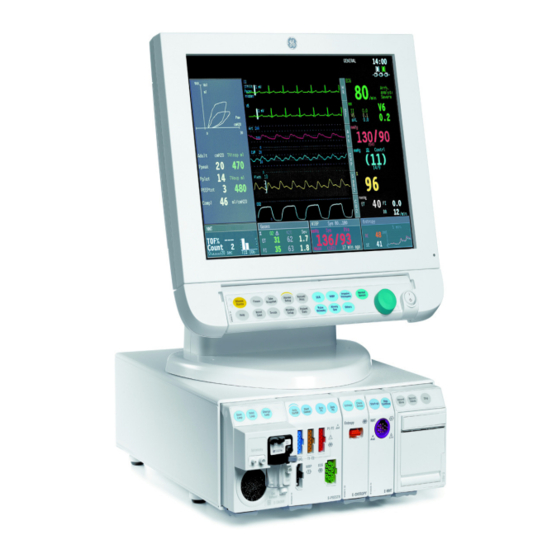
GE Datex-Ohmeda S/5 Technical Reference Manual (453 pages)
Anesthesia Monitor, Critical Care Monitor
Brand:
GE
| Category:
Medical Equipment
| Size: 12.26 MB
Table of Contents
Table of Contents
7
About this Manual
13
1 Introduction
15
Figure 1 Datex-Ohmeda S/5 Anesthesia Monitor System
15
Symbols
16
Symbols on Transport Packaging
16
Symbols on Equipment
17
Equipment Safety Symbols
18
Other Symbols
19
Safety
23
Safety Precautions
23
Disposal
27
ESD Precautionary Procedures
27
2 System Description
29
Introduction
29
Bus Structure
29
Figure 2 General Bus Structure of S/5 System
29
Distributed Processing
30
Module Communication
30
Figure 3 Distributed Processing in S/5 System
30
Software Loading
31
Figure 4 Principle of UPI Section Operation
31
Figure 5 Software Loading
31
Parameter Modules
32
Figure 6 General Structure of Parameter Modules with Patient Isolation
32
3 System Installation
33
Unpacking Instructions
33
Choosing Location
33
Central Unit; S/5 8-Module Frame, F-CU8
34
Connecting to Mains
34
Connecting to the Datex-Ohmeda Network
34
Figure 7 Central Unit: S/5 8-Module Frame, F-CU8
34
Figure 8 Module Insert
35
Inserting the Parameter Modules
35
E-PSM(P) Mounting Accessories
36
Figure 9 E-PSM(P) Mounting Accessories
36
Figure 10 Rear View and Positioning, F-CU8 (-12 Shown)
38
Positioning PC Boards
38
Figure 11 Service Reset Button
39
Replacing PC Boards
39
Performing Factory Reset
40
Central Unit; S/5 5-Module Frame, F-CU5
40
Figure 12 F-CU5 Parts Connected with Cables
41
Figure 13 Two F-Cu5S Connected to One F-CPU
41
Mounting the Frame
41
Connecting to Mains
42
Connecting to the Datex-Ohmeda Network
42
Inserting the Parameter Modules
43
Positioning PC Boards
44
Figure 15 Service Reset Button
45
Performing Factory Reset
45
Replacing PC Boards
45
Displays
46
3Rd Display
46
Display Installation
46
Figure 16 Display Options
46
Main Displays
46
Secondary Displays
46
15" Flat Panel Display, D-FPD15
47
12" LCD Display, D-LCC12A
48
19" Medical Grade Display
49
Display Controller Boards
50
Figure 17 Address Dip Switch Settings, B-DISPX
50
Jumper Settings
50
Resolution Selection for Optional B-DISPX
51
Resolution Selection for Primary Display
51
S/5 Remote Controller, K-REMCO
51
Figure 18 Resolution Dip Switch Settings, B-DISPX
51
S/5 Airway Modules
52
Figure 19 Compact Airway Module, E-XXXX
52
S/5 Compact Airway Modules, E-XXXX
52
Sample Gas Exhaust
52
Figure 20 Scavenging through Ventilator Reservoir
53
Figure 21 Connecting the Gas Module to the Scavenging Connector of S/5 Avance
53
Record Keeping Keyboard for Anesthesia, K-ARKB
54
Connection to Central Unit
54
Connection to LCD Display, D-LCC12A
54
Figure 22 Sample Gas Returned to Patient Circuit in ADU
54
ARK Barcode Reader, N-SCAN (Optional)
55
Connection to Central Unit/Lcd Display or D-LCC12A
55
Figure 23 Barcode Reader Connected to LCD Display
55
S/5 Extension Frame, F-EXT4, with F-CU8 Only
56
Figure 24 N-SCAN Barcode Reader Connection Directly to the Keyboard
56
Figure 25 S/5 Extension Frame, F-EXT4
56
Connection to Central Unit
57
Inserting the Parameter Modules
57
Mounting of Extension Frame, F-EXT4
57
Troubleshooting
57
4 Interfacing
59
Interfacing External Monitors Via Interface Module, E-INT
59
Connection to External Datex-Ohmeda Monitors
60
Connection to Baxter Vigilance
61
Connection to Critikon Dinamap 1846SX, Abbott Oximetrix 3 and Baxter Explorer
61
Connection to Nellcor N-100 and N-1000
61
Connection to Nellcor N-200
61
Interfacing External Bedside Devices Via Device Interfacing Solutions, N-Disxxx
63
Connections
64
Device Interfacing Solution Components
64
Figure 26 Connection Cables and LED Indicators
65
Mounting
65
Figure 27 an Example of Interfacing External Devices with Device Interfacing Solution
66
Selecting the External Device
66
Functional Check
67
Selecting the Parameter Data Source
67
Interfacing Datex-Ohmeda Anesthesia Delivery Unit
68
Interconnection
68
Setting Interfacing Parameters on the S/5 Anesthesia Delivery Unit
68
Setting Interfacing Parameters on the S/5 Anesthesia Monitor
68
Interfacing Dräger Cicero, Cato, Julian and Narkomed 2C (by NAD)
69
Interconnection
70
S/5 Critical Care Monitor
70
Setting Communication Parameters
70
Setting Interfacing Parameters on the S/5 Anesthesia Monitor or
70
Interfacing Printer
72
Interconnection
72
S/5 Critical Care Monitor
72
Setting Interfacing Parameters on the Printer
72
Setting Interfacing Parameters on the S/5 Anesthesia Monitor or
72
Interfacing Computer
72
Output Signals
73
Digital Outputs
73
UPI4NET Board Output Signals
73
Analog Outputs
74
S/5 Pressure Temp Module, E-PT, Output Signals
74
5 Functional Check
75
Recommended Tools
75
Hemodynamic Patient Simulators
77
Visual Inspection
77
Functional Inspection
78
General
78
Display(S)
79
Keyboard(S)
79
5-Module Central Unit, F-CU5/ 8-Module Central Unit, F-CU8
80
Compact Airway Module, E-CXXXXX
80
Extension Frame, F-EXT4
80
Multiparameter Hemodynamic Modules
81
Single Width Airway Module, E-Minic
81
Cardiac Output Modules, E-COP, E-Copsv
82
Dual Pressure Module, E-PP
82
Pressure/Pressure Temp Modules, E-P, E-PT
82
BIS Module, E-BIS
83
Entropy Module, E-ENTROPY
83
Masimo Compatible Saturation Module, E-MASIMO
83
Memory Module, E-MEM
83
Nellcor Compatible Saturation Module, E-NSATX
83
Device Interfacing Solution, N-Disxxx
84
Interface Module for PSM, E-INTPSM
84
Interface Module, E-INT
84
Network Connection
84
Recorder Module
84
General
85
6 General Troubleshooting
87
Figure 28 S/5 AM, CCM General Troubleshooting Flowchart
87
Software Troubleshooting
88
Appendix A: Functional Check Form, Datex-Ohmeda S/5 AM, CCM
89
Appendix B: Electromagnetic Compatibility
95
Planned Maintenance Instructions/Planned Maintenance Check List
101
1 Planned Maintenance Instructions
103
Introduction
103
Recommended Tools
104
Hemodynamic Patient Simulators
105
Recommended Parts
106
Planned Maintenance Parts
107
Anesthesia and Critical Care
107
PM Parts for Airway Module, E-Minic
107
PM Parts for Compact Airway Modules, E-CXX with CO2 Absorber
107
2 Planned Maintenance Check List
109
Visual Inspection/Preparation
109
Compact Airway Module, E-CXX
109
Extension Frame, F-EXT4
109
General
109
Recorder Module
110
Single-Width Airway Module, E-Minic
110
Modules with NIBP Measurement
111
Functional Inspection
111
General
111
5-Module Frame, F-CU5(P) / 8-Module Frame, F-CU8
113
Display
113
Keyboard(S)
113
Compact Airway Module, E-CXXXXX
114
Extension Frame, F-EXT4
114
Single-Width Airway Module, E-Minic
115
Multiparameter Hemodynamic Modules
116
10BIS Module, E-BIS
118
EEG Module, E-EEG and EEG Headbox, N-EEG
118
15Neuromuscular Module, E-NMT
121
19Recorder Module, E-REC
123
Table of Contents
133
Introduction
137
1 Frame
139
Display Controller
140
Memory
141
Network
141
Network Status
141
Network Config
142
Ethernet
143
Memcards
144
Status
144
Communication
145
Power Supply
146
Battery
146
CPU Board
147
2 Display
148
3 Keyboard
149
Keyboard Log
150
Keyboard Type
150
4 Parameters
151
Gas Unit
151
General
152
Gases
153
Spirometry
154
ECG Module
156
ECG Setup
157
ESTP Module
158
Calibrations
160
P/Pt
161
P/PT Calibrations
162
PP Calibrations
164
Cop
165
COP Calibrations
166
NIBP Module
167
NIBP Demo
168
NIBP Calibration
169
NIBP Safety Valve
170
NIBP Pulse Valve
171
NIBP Buttons/Leds
172
NIBP Pneumatics
173
NIBP Watchdog
174
Nmt
175
NMT Setup
176
Oxygen Saturation Module, E-NSATX, E-MASIMO
177
More
178
Interface Module, E-INT
179
Tonometry
180
Tonometry
184
Press Sensor
185
System Test
186
Pneumatics
189
Eeg & Ep
191
EEG & EP Setup
193
Bis
194
BIS Setup
200
Entropy
201
DIS Interfacing
203
Interfacing
203
DIS Interfacing Service Menu
204
Status Page
204
DIS Module Specific Page
205
DELP Service Menu
206
5 Set/Test
207
Country Settings
208
6 Service Log
209
Maintenance
210
Planned Maintenance
210
Repair
211
Upgrade
211
Error History
212
Event History
212
Alarm History
213
7 Record Data
214
8 SW Download
215
Appendix A: How to Read HEX Numbers
217
Table of Contents
221
Introduction
223
1 Specifications
224
8-Module Frame, F-CU8
224
Electrical Requirements
224
Environmental Requirements
224
2 Functional Description
225
8-Module Frame, F-CU8
225
Power Supply Unit, F-CU8 Rev.12
226
CPU Mother Board
231
Module Mother Board
231
Connectors and Signals
231
External Connectors
232
Internal Connectors
233
3 Service Procedures
234
General Service Information
234
Service Check
234
Recommended Parts
234
Recommended Tools
234
Visual Inspection
235
General Inspection
237
Disassembly and Reassembly
241
Before Disassembly
241
To Remove and Disassemble the Power Supply Unit
241
Tools Needed
241
To Remove the CPU Mother Board and the Module Mother Board
247
Replacing the Fuses
249
Adjustments and Calibrations
250
4 Troubleshooting
251
Central Unit
252
Digital Section
253
5 Earlier Revisions
254
Appendix A: Service Check Form, Datex-Ohmeda 8-Module Frame, F-CU8
255
Table of Contents
259
Introduction
263
1 Specifications
264
5-Module Frame, F-CU5
264
Electrical Requirements
264
Environmental Requirements
264
2 Functional Description
265
F-CU5 Central Unit
265
F-CU5 Power Unit, N-AC
266
Central Processor Unit, F-CPU
268
DC Power Board
268
Connectors
270
CPU Mother Board
270
External Components
270
5-Module Frame, F-CU5(P)
271
DC Power Board
271
External Connectors and Signals
273
5-Module Frame, F-CU5(P)
273
Power Unit, N-AC and Central Unit, F-CPU
276
3 Service Procedures
280
General Service Information
280
Service Check
280
Recommended Parts
280
Recommended Tools
280
Visual Inspection
281
General Inspection
283
5-Module Frame Disassembly and Reassembly
288
Before Disassembly
288
To Disassemble the 5-Module Frame, F-CU5(P)
288
Tools Needed
288
Central Processing Unit, F-CPU
292
Power Unit N-AC
294
4 Troubleshooting
295
Digital Section
297
5 Earlier Revisions
298
Appendix A: Service Check Form, Datex-Ohmeda 5-Module Frame, F-CU5
299
Table of Contents
303
Introduction
305
1 Specifications
306
Integrated Ethernet Controller
306
Integrated Display Controller
306
2 Functional Description
308
CPU Board, B-CPU6
308
Integrated Display Controller
309
Integrated Ethernet Controller
309
Powerfail or Standby
309
Sram M48T37V
309
Watchdog Functions
309
Ethernet Interface
310
Software License
310
Connectors and Signals
311
DVI-I Connector
311
Ethernet Network Interface
313
3 Service Procedures
314
General Service Information
314
Service Check
314
Recommended Tools
314
Functional Inspection
315
Disassembly and Reassembly
319
Downloading/Replacing Software on CPU Board, B-CPU6
319
Performing Factory Reset
319
Adjustments and Calibrations
319
4 Troubleshooting
320
Troubleshooting for the Ethernet Section
320
Troubleshooting Flowcharts
322
Error Messages
324
RAM Error
324
SRAM Error
324
5 Earlier Revisions
325
Appendix A: Service Check Form, CPU Board
327
Table of Contents
331
Introduction
333
1 Technical Specifications
334
General
334
Upi
334
NET (Ethernet)
334
2 Functional Description
335
General
335
UPI4NET Board, B-UPI4NET
335
NET Section
336
Connectors and Signals
336
Network Coding Element Interface
336
DIS Interface (RS422)
337
RS232 Serial Data Interface
337
Synchronization Interface
337
Printer Interface
338
Connection to the S/5 Bus
339
3 Service Procedures
340
Service Check
340
Recommended Tools
340
Visual Inspection
340
Functional Inspection
341
4 Troubleshooting
343
5 Earlier Revisions
344
Appendix A: Service Check Form, UPI4NET Board, B-UPI4NET
345
Table of Contents
349
Introduction
351
1 Specifications
352
LCD Display, D-LCC12A-01
352
15" Flat Panel Display, D-FPD15-00
352
19" Medical Grade Display
353
Display Controller Board, B-DISPX-01
353
2 Functional Description
355
LCD Displays
355
D-Lcc12A
355
15" Flat Panel Display, D-FPD15
356
19" Medical Grade Display
356
External Connector Configurations
357
Display Controller Board, B-DISPX-01
358
Output Connectors, B-DISPX-01
362
3 Service Procedures
364
General Service Information
364
15" Flat Panel Display, D-FPD15
364
19" Medical Grade Display
364
LCD Display, D-LCC12A
364
Service Check
364
LCD Display, D-LCC12A
365
15" Flat Panel Display, D-FPD15
367
19" Medical Grade Display
369
Disassembly and Reassembly
371
LCD Display, D-LCC12A
371
15" Flat Panel Display, D-FPD15
372
19" Medical Grade Display
372
4 Troubleshooting
373
LCD Displays
373
D-Lcc12A
373
15" Flat Panel Display, D-FPD15
374
19" Medical Grade Display
374
Display Controller Board, B-DISPX
375
5 Earlier Revisions
376
Appendix A: Service Check Form, LCD Display, D-LCC12A
377
Appendix B: Service Check Form, 15" Flat Panel Display, D-FPD15
379
Appendix C: Service Check Form, 19" Medical Grade Display
381
Table of Contents
385
Introduction
387
1 Specifications
388
Command Bar, K-ANEB/K-ICUB
388
2 Functional Description
389
Command Bars, K-ANEB/K-ICUB
389
Command Bar PCB
389
Comwheel
389
Connectors and Signals
390
Leds
390
3 Service Procedures
391
General Service Information
391
Service Check
391
Recommended Tools
391
Visual Inspection
391
Functional Inspection
392
Disassembly and Reassembly
394
Command Bar, K-ANEB/ K-ICUB
394
4 Troubleshooting
395
K-Aneb/ K-Icub
395
5 Earlier Revisions
396
Appendix A: Service Check Form, Command Bar, K-ANEB/K-ICUB
397
Table of Contents
401
Introduction
403
1 Specifications
404
General Specifications
404
2 Functional Description
405
Connectors and Signals
407
Module Bus Connector
407
3 Service Procedures
409
Service Check
409
Recommended Tools
409
Visual Inspection
409
Functional Inspection
411
Disassembly and Reassembly
413
Changing the Fuse
413
4 Troubleshooting
414
Troubleshooting Chart
414
5 Earlier Revisions
415
Appendix A: Service Check Form, Extension Frame, F-EXT4, Extension Module, E-EXT
417
Table of Contents
421
1 Software Licenses
423
Service Software Licenses
423
CPU Board, B-CPU6
426
UPI4NET Board, B-UPI4NET -02
426
Display Controller Board, B-DISPX -01
426
5 Module Frame, F-CU5
427
5-Module Frame Unit, F-CU5(P) -01
427
Central Processor Unit for F-CU5, F-CPU -02
431
F-CU5 Power Unit, N-AC
434
8 Module Frame, F-CU8
435
8-Module Frame, F-CU8 -12
435
5 Displays
439
LCD Display, D-LCC12A
439
Front Panel Stickers for D-LCC12A, Rev. 01
440
15" Flat Panel Display (D-FPD15)
440
19" Medical Grade Display
441
6 Extension Frame
442
Extension Module, E-EXT
443
7 Command Bar, K-ANEB, K-ICUB
445
Command Bar, K-ANEB, K-ICUB, Rev.00
445
Command Bar, K-ANEB
445
Command Bar, K-ICUB
446
Related Products
GE Vivid S5 N
GE SIGNA PIONEER
GE SIGNA Voyager
GE Voluson S10
GE Vivid S60
GE Vivid S70
GE Vivid S60N
GE Vivid S6 N
GE Senographe DS
GE Solar 7000
GE Categories
Refrigerator
Ranges
Microwave Oven
Air Conditioner
Dishwasher
More GE Manuals