beautypg.com
Manuals
Brands
Allen-Bradley Manuals
Controller
PowerFlex 755T
Allen-Bradley PowerFlex 755T Manuals
Manuals and User Guides for Allen-Bradley PowerFlex 755T. We have
7
Allen-Bradley PowerFlex 755T manuals available for free PDF download: User Manual, Installation Instructions Manual, Product Information, Original Instructions
Allen-Bradley PowerFlex 755T User Manual (270 pages)
Integrated Safety Functions Option Module
Brand:
Allen-Bradley
| Category:
Control Unit
| Size: 20.79 MB
Table of Contents
Table of Contents
3
Conventions
9
Preface
9
Terminology
10
Product Firmware and Release Notes
12
Additional Resources
13
What Is the Integrated Safety Functions Option Module
15
Chapter 1
17
Compatible Drives
17
Compatible Safety Controllers
17
Safety Application Requirements
18
Safety Certification
18
Important Safety Considerations
18
Stop Category Definitions
19
Performance Level and Safety Integrity Level (SIL) CL3
19
Proof Tests
20
PFD and PFH Definitions
20
PFD and PFH Data
21
Safety Data for Safe Torque off
21
Safety Data for Safe Feedback
21
Safety Data for Safety I/O
23
Spurious Trip Rate
23
Safety Reaction Time
24
Considerations for Safety Ratings
24
Encoder Considerations
25
Supported Encoders
25
Encoder Diagnostics
25
General Encoder Diagnostics
25
Digital Aqb Diagnostics
27
Sine/Cosine and Hiperface Diagnostics
27
Contact Information if Safety Option Failure Occurs
29
Installation
31
Chapter 2 Remove Power to the System
32
Access the Control Pod
32
Set the SAFETY and Hardware ENABLE Jumpers
33
Install the Safety Option Module
34
Feedback Installation Guidelines
35
I/O Wiring
36
Cabling
36
Power Supply Requirements
37
Chapter 3 Safety Inputs
39
Safety Input Operation
39
Latch Input Error Operation in Single Channel Mode
41
Single Channel Safety Input Status Data
42
Dual-Channel Safety Input Operation
43
Equivalent Dual-Channel Input Operation
44
Complementary Dual-Channel Input Operation
45
Standard Input Operation
46
Safety Input Safety Data
46
Safety Input Alarms
49
Determining Safety Input Alarm Type
50
Safety Input Alarm Recovery
51
Input Delays
51
Use with Powerflex 750-Series ATEX Option Module
52
Safety Outputs
52
Safety Output with Test Pulse
52
Single-Channel Mode
53
Latch Output Error Operation in Single Channel Mode
54
Dual-Channel Mode
55
Latch Output Error Operation in Dual Channel Mode
55
Safety Output Safety Data
57
Commanding Safety and Test Outputs
59
Safety Output Alarms
60
Determining Safety Output Alarm Type
61
Safety Output Alarm Recovery
62
Test Output
62
Standard Output Mode
63
Test Output Mode
63
Power Supply Output
63
Test Output Data
63
Test Output Status
64
Test Output Ready
65
Chapter 4 Safety Output Assembly Safe Stop Function Tags
67
Safety Input Assembly Safe Stop Function Tags
68
Safety Function in Response to Connection Event
70
Connection Loss Action
70
Connection Idle Action
71
Safe Torque off Function
71
Safe Torque off Activation
72
Safe Torque off Reset
72
Safe Torque off Delay
73
Safe Torque off Operation
74
Safe Torque off Stopping Action and Source
76
STO Safety Fault
77
Rockwell Automation Publication 750-UM005A-EN-P - October
77
Safe Stop 1 Function
78
Safe Stop 1 Activation
78
Safe Stop 1 Reset
79
Safe Stop 1 Stopping Action and Source
80
Timed Safe Stop 1
80
Monitored Safe Stop 1
81
SS1 Safety Fault
84
Safe Brake Control Function
85
Safe Brake Control Activation
85
Safe Brake Control Reset
86
Safe Brake Control Modes
87
Safe Brake Control Operation
88
SBC Safety Fault
93
Connecting a Safety Brake
93
Drive Safety Instructions
95
Drive-Based Safe Stop Functions
67
Chapter 5
97
Before Adding the Safety Instructions
97
Drive Safety Instruction Example
97
Pass-Through Data Using Standard I/O Mode
98
Pass-Through Data Using Integrated Motion
100
SFX Instruction
101
SFX Instruction Example
102
Chapter 6
105
Safety Assembly Tags
105
Configure Safety in the Logix Designer Application
106
Safety Controller Project
106
Add an Option Module to a Powerflex 755 Drive
108
Generate the Safety Network Number (SNN)
110
Safety Configuration Signature and Ownership
125
Reset Ownership
126
Programming
126
Safety Tags in Standard Routines
126
Standard Tags in Safety Routines (Tag Mapping)
126
Standard and Safety Tasks
127
Safety Function Operation
127
Pass-Through Data
129
Falling Edge Reset
129
Understand Integrated Safety Drive Replacement
129
Replace an Integrated Safety Drive in a Guardlogix System
130
Powerflex 755 IO Mode Using SFX, SS1, and SLS Instructions
132
Studio 5000 Logix Designer Application Configuration
132
Programming Example
135
Chapter 7 Add a Powerflex 755 Drive to the Controller Project
144
Understand Module Properties Categories
145
Module Properties>General Category
146
Module Properties>Connection and Safety Categories
149
Motion Safety>Actions Category
152
Motion Safety>Primary Feedback Category
153
Motion Safety>Secondary Feedback Category
155
Motion Safety>Scaling Category
156
Motion Safety>Discrepancy Checking Category
157
Motion Safety>Sto Category
158
Motion Safety>Ss1 Category
159
Motion Safety>Sbc Category
160
Motion Safety>Input Configuration Category
161
Motion Safety>Test Output Category
162
Motion Safety>Output Configuration Category
163
Axis Properties > Actions > Safety Actions
164
Feedback Device
165
Generate the Safety Network Number (SNN)
166
Safety Configuration Signature and Ownership
167
Reset Ownership
168
Motion Direct Commands in Motion Control Systems
169
Programming
176
Safe Monitor Network Communication
179
Explicit Messages
183
With Integrated Motion
184
Studio 5000 Logix Designer Application Configuration
185
Programming Example
187
Chapter 8
196
Module Status Indicator (DS1)
196
Motion Output Status Indicator (DS3)
197
Understand Safety Faults
199
Rockwell Automation Publication 750-UM005A-EN-P - October
200
Safe Stop 1 Fault
201
Safe Brake Control Fault
202
Safety Feedback Faults
203
Safety Fault Reset
204
Monitor Status with a HIM or Software
205
Monitor Status Using Integrated Motion
210
Out-Of-Box State
214
Checklist Safe Stop 2 (SS2)
220
Appendix A
223
Safe Operating Speed (SOS)
223
Safely-Limited Speed (SLS)
225
Safely-Limited Position (SLP)
226
Safe Direction (SDI)
228
Safe Feedback Interface (SFX)
229
Safe Brake Control (SBC)
231
Appendix B
235
Environmental Specifications
235
Certifications
236
EMC Directive (2014/30/EU)
237
Appendix C
247
Safe Stop Function Attributes
247
Explicit Messages
251
Parameters and Settings in a Linear List
253
Host Config Parameters
259
Index
263
Allen-Bradley PowerFlex 755T User Manual (193 pages)
PowerFlex 750-Series Drives with TotalFORCE Control Built-in EtherNet/IP Adapter
Brand:
Allen-Bradley
| Category:
Adapter
| Size: 9.79 MB
Table of Contents
Important User Information
2
Preface
11
Getting Started Components
16
Dual Ethernet Ports
17
Required Equipment
18
User-Supplied Equipment
19
Choose an Ethernet Switch
20
Safety Precautions
21
Configure the Interface Configuration Tools
24
Connecting the Interface to the Network
27
Apply Power
28
Start-Up Status Indications
29
Drive and Interface Start-Up Status Indications
30
Configuring and Verifying Key Drive Parameters
31
To Access Parameters
32
Using a BOOTP or DHCP Server
34
Setting the Data Rate
38
Setting Communication Hierarchy
39
Setting a Fault Action
42
Setting the Fault Configuration Parameters
43
Viewing the Interface Status Using Parameters
45
System Uploading the Electronic Data Sheet (EDS) File
50
Obtain Add-On Profiles
51
Adding the Bridge to the I/O Configuration
52
Add the Drive to the Project
54
Configure Input and Output Data
57
Download the Configuration to the Controller
60
Correlate the Drive with the Controller
62
Updating the Aops and Database Files
63
Configuration to Aid in Field-Failure Replacement
65
Using an Ethernet Switch with DHCP/BOOTP Server
66
Using Firmware Supervisor
67
Using Automatic Device Configuration (ADC)
69
Configure a Powerflex 755T Drive for ADC
71
ADC and Logix Memory
74
Special Considerations for 20-750-S1 Safe Speed Module (S1)
75
Developers Kit Option Cards
77
Monitoring ADC Progress
78
Drive Status Indicators - Operational
79
Logix Control ADC Failure Examples
80
Configuration Signature
81
Best Practices
83
Understanding the Controllogix Controller I/O Image
86
Using Logic Command/Status
87
Powerflex755T Drives Example Velocity Reference/Feedback Scaling
88
Using Datalinks
89
Example of Ladder Logic Program Information
90
Chapter 5 Using Explicit Messaging about Explicit Messaging
94
Explicit Messaging Compatibility with Powerflex 755T Drive
95
Performing Explicit Messaging
96
Controllogix Controller Examples
97
Formatting a Message to Read a Single Parameter
98
Ladder Logic Program to Write a Single Parameter
99
Formatting a Message to Write a Single Parameter
100
Ladder Logic Program to Read Multiple Parameters
101
Formatting a Message to Read Multiple Parameters
102
Ladder Logic Program to Write Multiple Parameters
104
Formatting a Message to Write Multiple Parameters
105
Rockwell Automation Publication 750COM-UM009A-EN-P - May
106
Scattered Read Multiple Messaging
107
Data Structures for Scattered Write Messages
108
Viewing Interface Diagnostic Items
111
Viewing and Clearing Events
114
Drive Status Indicators
116
ENET Status Indicator
117
LNK2 Status Indicator
118
Understanding the Status Indicators
119
ENET Status Indicator
120
LINK Status Indicators
121
Communication
123
How Parameters Are Organized
125
Parameter List
126
Supported Data Types
133
Identity Object
134
Assembly Object
135
PCCC Object
136
PCCC Object: Message Structure for Execute_Pccc
137
N-File Descriptions (All N-Files Are 16-Bit Integers)
138
DPI Device Object
140
DPI Device Object: Nonvolatile Class Attributes
141
DPI Parameter Object
143
DPI Parameter Object: Class Attributes
144
DPI Parameter Object: Instance Attributes
145
DPI Parameter Object: Descriptor Attributes
148
DPI Parameter Object: Extended Descriptor Attributes
149
Formulas for Converting
150
DPI Parameter Object: Common Services
151
DPI Fault Object
152
DPI Fault Object: Class Attributes
153
DPI Alarm Object
154
DPI Alarm Objects: Instance Attributes
155
DPI Diagnostic Object
156
DPI Time Object
157
DPI Time Object: Services
158
DPI Time Object: Instance Attributes
159
Host DPI Parameter Object
161
Host DPI Parameter Object: Instance Attributes
162
Host DPI Parameter Object: Descriptor Attributes
165
Host DPI Parameter Object: Extended Descriptor Attributes
166
Formulas for Converting
167
Host DPI Parameter Object: Object Specific Services
168
TCP/IP Interface Object
169
Ethernet Link Object
171
Rockwell Automation Publication 750COM-UM009A-EN-P - May
172
Drive Products
173
Logic Status Word
174
Bus Supply Products
176
Logic Status Word
177
Glossary
179
Index
187
Rockwell Automation Publication 750COM-UM009A-EN-P - May
188
Rockwell Automation Support
192
Documentation Feedback
192
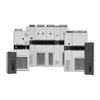
Allen-Bradley PowerFlex 755T Installation Instructions Manual (192 pages)
PowerFlex 750-Series Products with TotalFORCE Control
Brand:
Allen-Bradley
| Category:
Controller
| Size: 46.06 MB
Table of Contents
Installation
3
Table of Contents
3
Additional Resources
5
Chapter 1 General Precautions
7
Catalog Number Explanation
10
Product Rating Cross-References
13
Commonly Used Tools
16
Hardware Installation Diagrams
17
Fastener Torque Sequences
18
Receiving
19
Chapter 2
20
Shipment Configurations
20
Handling
22
Storage
25
Chapter 3 CE Conformity
27
Location Planning
31
Minimum Clearances
32
Mounting Options
35
Mounting Hardware
39
Approximate Dimensions
39
Frame 11 Drives Top, Front, and Bottom Views
43
Frame 12 Drives Top, Front, and Bottom Views
44
Drives Optional Entry and Exit Wire Bays Top, Front, and Bottom Views
45
Optional Entry Wire Bays Top, Front, and Bottom Views
51
Frame 9 Top, Front, and Bottom Views
53
Frame 10 Top, Front, and Bottom Views
54
Frame 11 Top, Front, and Bottom Views
55
Frame 12 Top, Front, and Bottom Views
56
Recommended Cabinet Mounting Hardware
39
Installation Site Requirements
58
Prepare Enclosures
59
Chapter 4
60
Component Removal Requirements
60
Table of Contents
63
L0 L1
64
L0 L1 L2
64
Line Side Converter
64
Motor Side Inverter
64
Line Side Converter
65
L2 L3
66
Motor Side Inverter
68
Shipping Split Section
68
Remove Protective Guards
70
Remove Power Module
73
Remove LCL Filter Module
79
Place the Enclosures
85
Join Enclosures
87
Affix the Enclosures to the Floor
93
Electrical Interconnections
94
Fiber-Optic Connections
96
Chapter 5 Grounding Requirements
99
Power Cable Types Acceptable for 400
101
Motor Considerations
101
Bus Bar Locations
102
Field Connections
106
Recommended Cable Spacing
110
Fuses and Circuit Breakers
113
Motor Overload Protection
126
Short Circuit Current Rating
126
Input Contactor Precautions
126
Output Contactor Precaution
126
Bypass Contactor Precaution
127
Applying and Removing Power
127
Drive Power Jumper Configuration
127
I/O Wiring
135
Chapter 6 I/O Terminal Blocks
136
I/O Wiring I/O Terminal Blocks
136
Access Control Pod
138
Main Control Board
140
Hardware Enable Circuitry
141
Safety Enable Circuitry
142
Fiber Optic Interface Board
143
Option Module Installation
144
11-Series I/O Module
145
11-Series I/O Wiring Examples
148
22-Series I/O Module
154
22-Series I/O Wiring Examples
157
Safe Torque off Option Module
161
Safe Speed Monitor Option Module
163
Integrated Safety - Safe Torque off Option Module
165
Devicenet Option Module
166
Controlnet Option Module
167
Dual-Port Ethernet/Ip Option Module
168
Profibus Option Module
169
Bacnet/Ip Option Module
170
Single Incremental Encoder Option Module
171
Dual Incremental Encoder Option Module
173
Universal Feedback Option Module
177
Motor Power Cables
180
Feedback Device Resolution
180
Motor Feedback Wiring Examples
180
Rockwell Automation Publication 750-IN100B-EN-P - July
181
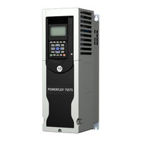
Allen-Bradley PowerFlex 755T User Manual (102 pages)
Integrated Safety - Safe Torque Off Option Module
Brand:
Allen-Bradley
| Category:
Control Unit
| Size: 10.01 MB
Table of Contents
Table of Contents
3
Conventions
7
Summary of Changes
7
Terminology
8
Product Firmware and Release Notes
9
Additional Resources
10
Chapter 1 What Is the Integrated Safety - Safe Torque off Option Module
11
Compatible Drives
12
Compatible Safety Controllers
13
Network Mode
13
Hardwired Mode
14
Safety Application Requirements
14
Safety Certification
14
Important Safety Considerations
14
Stop Category Definitions
15
Performance Level and Safety Integrity Level (SIL) CL3
15
Functional Proof Tests
16
PFD and PFH Definitions
16
PFD and PFH Data
17
Safety Reaction Time
17
Considerations for Safety Ratings
18
Contact Information if Safety Option Failure Occurs
18
Chapter 2 Remove Power from the Drive System
20
Access the Control Pod
20
Set the Safety Jumper
21
Install the Safety Option Module
22
Chapter 3 Description of Operation
25
Out-Of-Box State
26
Recognize Out-Of-Box State
26
Restore the Drive to Out-Of-Box State
26
Description of Integrated Operation
29
Chapter 4
30
Safe Torque off Assembly Tags
30
Configure Safe Torque off in the Logix Designer Application
31
Add a Powerflex 755 Drive to the Controller Project
33
I/O Mode
34
I/O Mode
37
Generate the Safety Network Number (SNN)
39
Configure Safety Connections
41
Safety Configuration Signature and Ownership
43
Reset Ownership
43
Safe Torque off - Stop Category 0 Example Program
44
Safe Torque off - Stop Category 1 Example Program
45
Falling Edge Reset
46
Safety Tags in Standard Routines
46
Standard Tags in Safety Routines (Tag Mapping)
46
Safe Torque off Fault Reset
47
Understand Integrated Safety Drive Replacement
48
Replace an Integrated Safety Drive in a Guardlogix System
48
Requirements
51
Chapter 5 Description of Operation
51
Safe Torque off Assembly Tags
52
Configure Safe Torque off in the Logix Designer Application
54
Add a Powerflex 755 Drive to the Controller Project
55
Configure an Option Card on a Powerflex 755 Drive in Integrated Motion on Ethernet/Ip Network Applications
56
Generate the Safety Network Number (SNN)
57
Configure Safety Connections
58
Safety Configuration Signature and Ownership
60
Reset Ownership
60
Safe Torque off - Stop Category 0 Example Program
61
Safe Torque off - Stop Category 1 Example Program
62
Falling Edge Reset
62
Safety Tags in Standard Routines
63
Standard Tags in Safety Routines (Tag Mapping)
63
STO Fault Reset
64
Troubleshoot the Safe Torque off Function
65
Understand Integrated Safety Drive Replacement
65
Replace an Integrated Safety Drive in a Guardlogix System
66
Motion Direct Commands in Motion Control Systems
67
Wiring
75
Chapter 6
76
Cabling
76
Power Supply Requirements
76
Description of Hardwired Operation
77
Selection of Hardwired Operation
77
Configure the Drive with Hardwired Safety Connections
77
Timing Diagrams
78
Rockwell Automation Publication 750-UM004B-EN-P - October
78
Chapter 7
81
Module Status Indicator (DS1)
81
Network Status Indicator (DS2)
82
Motion Output Status Indicator (DS3)
82
Monitor STO with a HIM or Software
83
Fault Messages on HIM, Drive Module, and Connected Components Workbench Software
83
Safety Supervisor State
86
Safe Torque off Faults
86
Integrated Safety - Safe Torque off Option Module
87
Monitor STO Status
81
Appendix A
87
Specifications
87
Environmental Specifications
88
Certifications
89
Waste Electrical and Electronic Equipment (WEEE)
89
Installation Considerations
91
Appendix B Option Module Slots
91
Wiring
92
Safe Torque off Option Module
92
Integrated Safety - Safe Torque off Option Module
92
Appendix C Parameters and Settings in a Linear List
93
Device Config Parameters
93
Host Config Parameters
95
Index
97
Allen-Bradley PowerFlex 755T Product Information, Original Instructions (48 pages)
Drives Configured to Order Program
Brand:
Allen-Bradley
| Category:
DC Drives
| Size: 15.2 MB
Table of Contents
Table of Contents
3
Introduction
5
Environmental Specifications
5
Catalog Number Explanation
6
Installation Location
6
Approximate Dimensions
6
Overhead Clearance
8
Airflow Clearances and Considerations
8
Service Cart Access Requirements
10
Recommended Mounting Hardware
11
Shipment Sections and Approximate Weights
11
Leakage Current
12
Duty Rating
12
Motor Overload Protection
12
Short-Circuit Current Rating
12
Branch Circuit Short-Circuit Protection
12
Fuses
12
Input Power Circuit Breakers
15
Grounding Requirements
17
Recommended Grounding Scheme
17
Grounding Clamps
17
Shield Termination - SHLD
17
RFI Filter Grounding
17
Electrical Connections Made to each Configured Bay During Installation
17
Frame 8 Electrical Connections
18
Frame 9 Electrical Connections
18
Component and Connection Locations
20
Frame 8 All Possible Configured Input Bay Upper Door External Components
21
Frame 8 Component and Connection Locations
21
Frame 8 Configured Input Bay Control-Only: Internal Components
22
Frame 8 Configured Input Bay with Fuses, Top Entry: Internal Components and Installation Connection Locations
23
Frame 8 Configured Input Bay with Fuses, Bottom Entry: Internal Components and Installation Connection Locations
24
Frame 8 Configured Input Bay with Circuit Breaker, Top Entry: Internal Components and Installation Connection Locations
25
Frame 8 Configured Input Bay with Circuit Breaker, Bottom Entry: Internal Components and Installation Connection Locations
26
Locations
27
Frame 9 Component and Connection Locations
29
Bay to Bay Connection Hardware
38
PE Ground Bar Splice Connection Hardware
38
AC Busbar Splice Connection Hardware
38
Barrel Lug to Drive Output Busbar Connection Hardware
38
Terminal Lug Connection Hardware
38
Braided Busbar to Drive Output Busbar Connection Hardware
39
Flexibar Flexible Busbar Connection Hardware
39
Barrel Lug to Drive Input Busbar Connection Hardware
40
Drive Main Control Board Connection Hardware
40
22-Series I/O Option Module Connection Hardware
40
Configured Bay Control Connection Hardware
41
Customer Connections for AC Line Input Power and Motor Power
44
Power Wiring Cable Recommendations
44
Connection Hardware for Customer Power Source and Motor
45
Join the Bays
46
Move the Bays
46
Additional Resources
47
Shipped with the Product
47
Online
47
Allen-Bradley PowerFlex 755T Installation Instructions Manual (24 pages)
Frames 5 and 6 Conduit Box with Debris Hood and Ground Plate Kits
Brand:
Allen-Bradley
| Category:
Industrial Equipment
| Size: 7.81 MB
Table of Contents
Table of Contents
1
Product Advisories
1
Required Tools
2
Frame 5 Conduit Box with Debris Hood Kit Contents (Cat. No. 20-750-CBOX1-F5)
2
Frame 5 Conduit Box Installation
3
Frame 6 Conduit Box with Debris Hood Kit (Cat. No. 20-750-CBOX1-F6)
9
Frame 6 Conduit Box and Debris Hood Installation
10
Frame 5 Ground Plate Kit Contents (Cat. No. 20-750-GNDPLT-F5)
16
Frame 5 Ground Plate Installation
17
Frame 6 Ground Plate Kit Contents (Cat. No. 20-750-GNDPLT-F6)
20
Frame 6 Ground Plate Installation
21
Additional Resources
23
Allen-Bradley PowerFlex 755T Installation Instructions Manual (16 pages)
Marine Discharge Kits
Brand:
Allen-Bradley
| Category:
Marine Equipment
| Size: 5.85 MB
Related Products
Allen-Bradley PowerFlex 753
Allen-Bradley PowerFlex 755
Allen-Bradley PowerFlex 750 Series
Allen-Bradley PowerFlex 755TL
Allen-Bradley PowerFlex 755TR
Allen-Bradley PowerFlex 755TM
Allen-Bradley PowerFlex 755 IP00
Allen-Bradley powerflex 700
Allen-Bradley PowerFlex 700S
Allen-Bradley PowerFlex 700L
Allen-Bradley Categories
Control Unit
Controller
I/O Systems
Power Supply
Switch
More Allen-Bradley Manuals