beautypg.com
Manuals
Brands
Allen-Bradley Manuals
Controller
PowerFlex 700H
Allen-Bradley PowerFlex 700H Manuals
Manuals and User Guides for Allen-Bradley PowerFlex 700H. We have
6
Allen-Bradley PowerFlex 700H manuals available for free PDF download: Hardware Service Manual, Programming Manual, Service Manual, Installation Instructions Manual
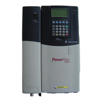
Allen-Bradley PowerFlex 700H Service Manual (115 pages)
High Performance AC Drive and Adjustable Frequency AC Drive
Brand:
Allen-Bradley
| Category:
Controller
| Size: 1.87 MB
Table of Contents
Table of Contents
3
Important User Information
2
Table of Contents
3
Preface
7
What Is in this Manual
7
What Is Not in this Manual
7
Who Should Use this Manual
7
Reference Materials
8
Terms
8
Understanding Manual Conventions
8
Additional Support Available on Internet
9
Cross References
9
Class 1 LED Product
10
General Precautions
10
Chapter 1 Creating Fault Reports
12
Addressing 700S Hardware Faults
12
Addressing 700H Hardware Faults
13
Diagnostic Procedures by Symptom
15
Blown Input Fuses
15
No Output Voltage
16
No HIM Display
17
Over-Temperature Faults
18
Chapter 2 Viewing the 700H Diagnostic LED
19
Viewing the 700S Diagnostic Leds
20
Performing Visual Inspections
22
Inspecting the Cooling Tunnels
22
Inspecting the Power Structure
22
Conducting Forward and Reverse Biased Diode Tests for Major Power Components
22
Checking Fiber Optic Connections to the Gate Driver Boards
25
Conducting Gate Driver Board Measurements
25
Gate Interface Resistance
26
Preparing the Drive for Active Measurements on the Gate Driver Board
26
Checking the Opto-Couplers
28
Checking the Rectifying Module(S) on AC Input Drives
30
Testing 600V AC Input, 460A and 502A Drives
30
Taking Measurements on Rectifying Module
31
Testing 400V AC Input, 590A, 650A or 730A, or 600V AC Input, 590A Drives
32
Taking Measurements on Rectifying Module
33
Checking the DC Bus Capacitors
35
Checking the Main Fan Inverters and Fans
36
Checking Fan Inverter Fuses
36
Checking Inverter Leds
36
Isolating a Faulty Fan Inverter
36
Checking the Main Fan Motors
37
Chapter 3 Torque Specifications
39
Understanding Torque Figures in Assembly Diagrams
41
Removing Power from the Drive
41
Removing Power
41
Removing the DPI / HIM Assembly
42
Removal
42
Installation
43
Installation
45
Removing the 700S Control Assembly
46
Installation
46
Removal
46
Removing the 700S High Power Fiber Optic Interface Circuit Board
47
Installation
47
Installation
49
Removing the Covers from the Power Structure
51
Installation
51
Moving the Control Frame
51
Removing the Airflow Plate
53
Removing the Protective Covers from Power Structure
54
Removal
55
Removing the 700S Voltage Feedback Circuit Board
55
Installation
56
Removing the Gate Driver Board
56
Removal
56
Installation
57
Removing the ASIC Board
58
Removal
58
Installation
59
Removing the Power Structure from the Drive Cabinet
59
Removal
59
Installation
62
Removing the Main Fans
62
Removal
62
Installation
63
Removing the Fan Inverters
63
Removal
63
Removing the U Phase (Left-Side) Output Power Module
67
Removal
67
Installation
70
Module
71
Removal
71
Installation
73
Module
74
Installation
77
Before Applying Power to the Drive
79
Chapter 4 Before Applying Power to the Drive
79
Testing with the External DC Power Supply Without Load (Optional)
80
Performing the Power Circuit Diagnostic Test on a 700S
81
Testing Without a Motor
81
Testing with the Motor
82
Appendix A Software Tools
83
Service Tools
83
Appendix Schematics
85
Appendix B List of Schematic Diagrams
86
Power Wiring Diagrams
86
Phase U Power Circuitry for Drives with AC Input
86
Phase V Power Circuitry for Drives with AC Input
87
Phase W Power Circuitry for Drives with AC Input
88
Phase U Power Circuitry for Drives with DC Input
89
Phase V Power Circuitry for Drives with DC Input
90
Phase W Power Circuitry for Drives with DC Input
91
Circuit Board Connections for 700H Drives with AC Input
92
Control Wiring Diagrams
92
Circuit Board Connections for 700H Drives with DC Input
93
Circuit Board Connections for 700S Drives - Phase II Control with AC Input
94
Circuit Board Connections for 700S Drives - Phase II Control with DC Input
95
Fan Inverter and Main Fan Connections
96
Hardware Connections
104
Appendix C Circuit Board Connections
105
Appendix D Disassembly/Assembly Diagrams and Spare Parts Numbers
105
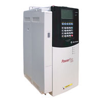
Allen-Bradley PowerFlex 700H Hardware Service Manual (120 pages)
High Performance/Adjustable Frequency AC Drive
Brand:
Allen-Bradley
| Category:
Controller
| Size: 1.7 MB
Table of Contents
Table of Contents
3
Preface
5
What Is in this Manual
5
What Is Not in this Manual
5
Who Should Use this Manual
5
Reference Materials
6
Understanding Manual Conventions
6
Additional Support Available on Internet
7
General Precautions
8
Chapter 1 Creating Fault Reports
10
Addressing 700S Hardware Faults
10
Addressing 700H Hardware Faults
12
Diagnostic Procedures by Symptom
13
Chapter 2 Viewing the 700H Diagnostic LED
17
Viewing the 700S Diagnostic Leds
18
Performing Visual Inspections
20
Conducting Forward and Reverse Biased Diode Tests for Major Power Components
20
Checking Fiber Optic Connections to the Gate Driver Boards
24
Conducting Gate Driver Board Measurements
24
Checking Rectifying Module (on AC Input Drives Only)
30
Checking the DC Bus Capacitors
33
Chapter 3 Torque Specifications
37
Removing Power from the Drive
39
Removing the 700S Phase II Control Assembly
46
Removing the 700S High Power Fiber Optic Interface Circuit Board
46
Removing the 700S Control Assembly Mounting Plate
46
Removing the 700H I/O Boards and Control Assembly
47
Removing the 700H Star Coupler Board
49
Removing the Covers from the Power Structures
51
Removing the 700S Voltage Feedback Circuit Board
55
Removing the Gate Driver and Adapter Boards
57
Removing the Power Structures from the Drive Enclosure
61
Removing the Main Fans
62
Removing the ASIC Boards
63
Removing the Rectifying Boards
65
Removing the Left-Side Output Power Modules
66
Removing the Right-Side Output Power Modules and Rectifying Modules
69
Removing the Fan Inverters
73
Chapter 4 Before Applying Power to the Drive
79
Testing with the External DC Power Supply Without Load (Optional)
80
Testing Without a Motor
81
Performing the Power Circuit Diagnostic Test on a 700S
81
Testing with the Motor
82
Appendix A Software Tools
83
Service Tools
84
Appendix Schematics
85
Circuit Board Connections for 700H Drives
87
ASIC Circuit Board Connections
88
Fan Power Supply Connections
93
AC Input Motor Connections
94
DC Input Motor Connections
95
Appendix B List of Schematic Diagrams
97
Appendix C Circuit Board Connections
97
For a Schematic Diagram on
97
Hardware Connections
106
Appendix D Disassembly/Assembly Diagrams and Spare Parts Numbers
109
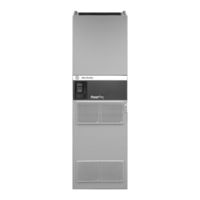
Allen-Bradley PowerFlex 700H Programming Manual (116 pages)
Adjustable Frequency AC Drive
Brand:
Allen-Bradley
| Category:
DC Drives
| Size: 2.47 MB
Table of Contents
Table of Contents
5
What Is Not in this Manual
7
Who Should Use this Manual
7
Additional Resources
8
General Precautions
8
Chapter 1
11
Prepare for Drive Start-Up
11
Start-Up the Drive
12
About Parameters
15
Chapter 2
17
How Parameters Are Organized
17
Monitor File
20
Motor Control File
21
Speed Command File
24
Dynamic Control File
30
Utility File
35
Communication File
45
Inputs/Outputs File
49
Parameter Cross Reference - by Name
56
Parameter Cross Reference - by Number
58
Chapter 3
62
Drive Status
62
Faults and Alarms
63
Manually Clearing Faults
63
Fault and Alarm Descriptions
64
Fault Subcodes
71
Clearing Alarms
77
Common Drive Symptoms and Corrective Actions
77
Technical Support Options
79
Appendix A
81
External and Internal Connections
81
LCD Display Elements
82
ALT Functions
82
Menu Structure
83
View and Edit Parameters
85
Remove and Install the HIM
86
Appendix B
87
External Brake Resistor
87
Minimum Speed
87
Motor Control Technology
88
Motor Overload
89
Overspeed
91
Power Loss Ride through
91
Process PI
93
Reverse Speed Limit
96
Skip Frequency
97
Sleep Wake Mode
99
Start at Power up
101
Stop Modes
101
Appendix C
103
Changes to this Manual
103
allen-bradley PowerFlex 700H Installation Instructions Manual (22 pages)
Fan Inverter Upgrade Kit
Brand:
allen-bradley
| Category:
Inverter
| Size: 1.34 MB
Allen-Bradley PowerFlex 700H Installation Instructions Manual (18 pages)
AC Drives Frames 13 and 14 Main Fan Capacitor Replacement Kit
Brand:
Allen-Bradley
| Category:
Controller
| Size: 2.44 MB
Allen-Bradley PowerFlex 700H Installation Instructions Manual (18 pages)
Frame 10 Replacement Power Structures
Brand:
Allen-Bradley
| Category:
DC Drives
| Size: 1.8 MB
Related Products
Allen-Bradley powerflex 700
Allen-Bradley PowerFlex 700S
Allen-Bradley PowerFlex 700L
Allen-Bradley PowerFlex 700 AFE
Allen-Bradley PowerFlex 700SE
ALLEN BRADLEY PowerFlex 7000
Allen-Bradley PowerFlex 755T
Allen-Bradley 7760
Allen-Bradley PowerFlex 755 IP00
Allen-Bradley 7761
Allen-Bradley Categories
Control Unit
Controller
I/O Systems
Power Supply
Switch
More Allen-Bradley Manuals