
Related Manuals for Bosch FR 120


Summary of Contents for Bosch FR 120
- Page 1 Room temperature controller with solar control FR 120 Installation and operating instructions...
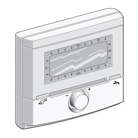
- Page 2 2 | Overview of controls and symbols Overview of controls and symbols advance advance menu info 6 720 617 762-01.2O Fig. 1 Controls 6 720 800 817 (2012/02)
- Page 3 Overview of controls and symbols | 3 Controls Symbols 1 Turn rotary selector in + direction: Current room temperature scroll menu/information up or increase setting Flashing segment: Turn rotary selector in – direction: Current time (09:30 to 09:45) scroll menu/information down or Solid segments: time set for decrease setting operating mode...
-
Page 4: Table Of Contents
4 | Contents Contents 5.3.3 Resetting an entire program Chapters against a grey (overwriting with factory settings) 23 background are intended for Resetting all settings (for heating contractors only) . . . 24 installers. The pages concerned Manually setting operating modes are identified by a grey vertical bar 5.5.1 Selecting the operating mode for at the side of the page. - Page 5 Contents | 5 Viewing information ....39 12 Commissioning report for the heating system ......60 Menu settings INSTALLER SETTINGS (for contractors only) .
-
Page 6: Key To Symbols And Safety Instructions
6 | Key to symbols and safety instructions Key to symbols and safety instructions Additional symbols Key to symbols Symbol Explanation Warnings Action step Warnings in this document are Cross-reference to other parts of framed and identified by a warning this document or to other triangle printed against a grey documents... -
Page 7: Safety Instructions
Key to symbols and safety instructions | 7 Safety instructions B These instructions must be observed to ensure correct operation. B Install and commission the heating appliance and all accessories in accordance with the instructions provided. B This accessory must only be installed by suitably qualified installers. -
Page 8: Technical Data For The Accessory Item
Heating appliance Heatronic 3 interface) Wall mounting 1 non-mixed heating circuit HK 2 ... HK 10 via FR 10/ FR 120 Time/temperature level profile for associated heating circuit Heat-up optimisation DHW heating DHW heating via heating appliance with DHW heating acc. -
Page 9: Standard Delivery
Technical data for the accessory item | 9 Standard delivery Supplementary accessories See also the pricelist. IPM 1: Module for controlling one • mixed or one non-mixed heating circuit. IPM 2: Module for controlling up to two mixed • heating circuits. Controlling one non-mixed heating circuit in the heating system is possible. -
Page 10: Sample System
230 V AC ...HK ZW... 230 V/AC S...solar 230 V/AC ISM 1 6 720 800 003-01.1O Fig. 3 FR 120 and combi boiler: Simplified system scheme (see technical guides for installation illustration and further options) 6 720 800 817 (2012/02) - Page 11 ISM 1 230 V/AC 6 720 800 003-02.1O Fig. 4 FR 120 and heating appliance with DHW cylinder connection: Simplified system scheme (see technical guides for installation illustration and further options) Key to Fig. 3 and Fig. 4: FR 10 Room temperature controller for S...solar Solar cylinder...
-
Page 12: Installation (For Contractors Only)
12 | Installation (for contractors only) Installation (for contractors only) The detailed system scheme for installing the The mounting surface on the wall hydraulic components and the associated control should be level. devices can be found in the technical guides or tender specifications. -
Page 13: Fitting Other Accessories
Installation (for contractors only) | 13 B Refit top section and slide cover on base. 3.1.2 Fitting other accessories B Fit accessories according to the legal requirements and the installation instructions supplied with them. 3.1.3 Disposal B Dispose of packaging in an environmentally responsible manner. -
Page 14: Electrical Connections
This classic type of Heatronic 3 control is highly suitable for combi boilers in apartments, for example, because the displays in FR 120 these systems are extremely ST 19 convenient. 4 B B B Use electrical cable according to local codes and requirements. -
Page 15: Interface
Installation (for contractors only) | 15 3.2.2 Connect the analogue 1-2-4 interface If the BUS links feature different Permissible lead lengths of FR 120 to the heating cross-sections: appliance: B Connect BUS links via a branch box. Lead length Cross-section ≤... -
Page 16: Commissioning (Contractors Only)
Program additional room temperature cont- CH circuit select code 1 with rollers FR 10 (not permissible in Germany) confirm with or FR 120 in accordance with the details in – If the controller is to control heating cir- the manual supplied. cuit HC 2...10... - Page 17 Commissioning (contractors only) | 17 13. Inform the system user about the functions and method of operation as follows: – The contractor explains to the customer how the heating appliance and controller work and how to operate them. – Explain to the user how to operate the system on a day-to-day basis, e.g.
-
Page 18: Operation
Why not take the trouble – it will be worth your while! The procedure for changing a switching With the FR 120 heating controller, you can point will illustrate everything you need to know automatically control the room and DHW... -
Page 19: Heating And Dhw Programs
Operation | 19 Heating and DHW programs 5.1.1 General Heating program The programs for heating and DHW enable you to The heating program regulates the heating achieve maximum energy savings while still operation. There are three modes for heating enjoying optimum comfort in terms of room operation: temperature and availability of hot water. -
Page 20: Display Views And Menu Navigation
If the DHW program changes from a higher to a lower temperature, the navigation water in the cylinder will not The user interface of the FR 120 room immediately cool to the lower temperature-dependent heating controller is temperature, i.e. water at a higher implemented as a so-called "menu". -
Page 21: Setting Programs
Operation | 21 A flashing parameter setting (e.g. switching • Setting programs time or operating mode) Setting and changing switching times and – can be changed with operating modes – can be deleted (reset to the default) with Setting programs and switching times always follows the same pattern. - Page 22 22 | Operation B Press B Press to confirm the menu point The Heating menu is selected and the title bar Monday. shows the current menu name (in this case The next submenu (EDIT PROGRAMME HEATING). MON) showing the programmed switching times and operating modes P1 to P6 is displayed.
-
Page 23: Deleting An Individual Switching
Operation | 23 B Turn until the required operating mode 5.3.2 Deleting an individual switching point (e.g. Economy) or temperature is shown. B Place the highlight onto the value to be The segment ring always shows the effect of deleted, as described in chapter , e.g. the change on the heating program. -
Page 24: Resetting All Settings (For Heating Contractors Only)
24 | Operation Resetting all settings (for heating contractors only) This function resets all settings of MAIN MENU and INSTALLER SETTINGS to their factory settings. Following such a reset, your heating contractor will need to recommission the system! If the standard display is set: B Simultaneously press and hold menu until the following warning message appears:... -
Page 25: Manually Setting Operating Modes
Operation | 25 5.5.2 Advancing heating mode before the Manually setting operating programmed time (bringing forward the modes next switching point) This function brings forward the time at which The information shown in the standard display operating mode Comfort / Economy and the operation only apply to the associated Frost or the specified room temperature set... -
Page 26: Changing Dhw Mode (Time-Limited)
26 | Operation 5.5.3 Changing DHW mode (time-limited) 5.5.4 Holiday program You can use this function if you want to set a You can use this function if you need constant operating mode for several days hot water outside the programmed (e.g. -
Page 27: Changing The Set Room Temperature
Operation | 27 Changing the set room If you have set the holiday program temperature to start on today's date, it will start immediately. If the date is in the The controller provides the option of future, the holiday program will setting the required room start at 00:00 h on the set start temperature for the operating mode... -
Page 28: Adjusting The Main Menu
28 | Adjusting the MAIN MENU Adjusting the MAIN MENU B Briefly push the menu key to open or close the The menu points are only shown if main menu. the system components are B Turn the rotary selector to select the required installed and/or active. - Page 29 Adjusting the MAIN MENU | 29 Domestic hot water DHW and DHW circulation pump page 32 DHW programme page 33 All days ... Sunday P1, P2, ... P6 Reset factory settings DHW circ pump prog page 34 All days ... Sunday P1, P2, ...
- Page 30 30 | Adjusting the MAIN MENU General settings page 37 Time and date Time Date Auto switch between GMT - BST Time adjustment Display format Date Display contrast Information at top of display Key lock Language Solar page 38 T2: Max. solar cylinder temperature Optimizing influence DHW 1) Subject to the equipment level of the installed system and the settings made, this menu or not all of its parameters may be displayed.
-
Page 31: Heating Program
Thursday at the same time with the selected operating mode). For each of the operating modes, there is a set room temperature stored on the FR 120 heating P1, P2 ... P6: Up to six switching times per •... -
Page 32: Temperature Levels For The Operating Modes
32 | Adjusting the MAIN MENU 6.2.2 Temperature levels for the operating DHW program modes Menu: Heating > Heating levels Main menu: Domestic hot water Use this menu to permanently set the Set the DHW temperature controller temperature levels for the 3 operating modes on the heating appliance to the (Comfort / Economy... -
Page 33: Time Program For Dhw With
Adjusting the MAIN MENU | 33 With DHW cylinder: 6.3.1 Time program for DHW with combi boiler • cylinder heating to the required temperature Menu: Domestic hot water > DHW programme starts 1 hour before the heating circuit changes over to operating mode Comfort Use this menu if you want to change a time (Cylinder temp at heating level Comf. -
Page 34: Timer/Temperature Program For Dhw With Dhw Cylinder
34 | Adjusting the MAIN MENU 6.3.2 Timer/temperature program for DHW The segments on the display show with DHW cylinder the periods for the following DHW temperature demands: Menu: Domestic hot water > DHW programme ≥ 50 °C – solid segments Use this menu if you required a DHW program ≤... -
Page 35: Dhw Parameters
Adjusting the MAIN MENU | 35 6.3.4 DHW parameters (only with DHW DHW circ pump cycles: • cylinder) This menu point is only active if the system has a DHW circulation pump. The DHW Menu: Domestic hot water > Parameter circulation pump stops during the DHW Cylinder temp at heating level Comf.: circulation pump Off phases. -
Page 36: Thermal Disinfection Of Hot Water (With Dhw Cylinder Only)
36 | Adjusting the MAIN MENU 6.3.5 Thermal disinfection of hot water (with Operating status: • DHW cylinder only) – Not running: No thermal disinfection at present. Once-only thermal disinfection Menu: Domestic hot water > Thermal can be started by selecting Start now. disinfection –... -
Page 37: General Settings
Adjusting the MAIN MENU | 37 General settings 6.4.1 Time and Date 6.4.2 Display formats Menu: General settings > Time and date Menu: General settings > Display format Use this menu if you want to correct the date and Use this menu if you want to customise the time. -
Page 38: Solar Settings
In order to use as much solar energy as possible, temperature or optimise the set DHW and flow the FR 120 heating controller can estimate the temperatures based on the available solar energy expected solar yield over the course of a day and in your geographical region. -
Page 39: Viewing Information
Viewing information | 39 Viewing information Menu: INFO INFO menu overview The table below provides the following: This menu allows you to view a variety of system An overview of the menu structure (column 1). information. • The menu depth is identified by various Detailed instructions on navigating through the shades of grey. - Page 40 Room temperature measured at the controller. Required heating output 45 % Output requested by the controller (only in the case of analogue connection of the FR 120 via 1-2-4 interface). Required CH flow 75.0 °C Flow temperature for the assigned heating circuit temperature calculated and requested by the controller.
- Page 41 Does not start until at least 30 days after commissioning. Faults 40 Solar system List of current faults. More detailed information can 03 FR 120 be displayed with to confirm. EA heating appliance 1) Only with DHW cylinder on the appliance.
-
Page 42: Menu Settings Installer Settings (For Contractors Only)
42 | Menu settings INSTALLER SETTINGS (for contractors only) Menu settings INSTALLER SETTINGS (for contractors only) An overview of the factory settings • The INSTALLER SETTINGS menu is (column 2), e.g. for the purposes of resetting intended only for contractors. individual menu points to their factory setting. -
Page 43: Heating Parameters
Menu settings INSTALLER SETTINGS (for contractors only) | 43 8.1.2 INSTALLER SETTINGS: Heating parameters Menu structure Factory Personal Description Heating parameters setting Setting range setting from page Calibrate room temperature 0.0 K – 3.0 K ... 3.0 K sensor Adjustment factor I 40 % 0 % ... -
Page 44: Installer Settings: Fault History
Boiler date of manufacture 27.06.2012 (data – – from heating appliance) Controller part number and 7 777 777 777 – – model FR 120 (fixed factory setting) Controller date of manufacture 27.06.2012 – – (fixed factory setting) Controller software version JF11.12 (fixed –... -
Page 45: Configuring The Heating System
Menu settings INSTALLER SETTINGS (for contractors only) | 45 Configuring the heating system Contractor level: System configuration When commissioning a heating system, proceed An example system is shown in as follows: chapter 2.5 on page 10. Other B Code all BUS subscribers in accordance with examples can be found in the their function (e.g. -
Page 46: Parameters For Heating
In that way the – Fit a suitable precision instrument near or controller is able to take account of FR 120. The precision instrument must not seasonal outside temperature fluctuations. transfer any heat to the FR 120. -
Page 47: Configuring The Solar Thermal
Menu settings INSTALLER SETTINGS (for contractors only) | 47 Configuring the solar thermal Parameters for solar thermal system system The heating system's solar thermal Fill and vent the solar thermal system has to be configured system according to its manually. Automatic configuration of documentation and prepare it for the heating system ( chapter 8.2,... -
Page 48: Commissioning The Solar Thermal
48 | Menu settings INSTALLER SETTINGS (for contractors only) 8.5.1 Commissioning the solar thermal system temperature (T2) drops below the set value, the solar circuit pump (SP) will be switched off. Contractor level: Solar sys parameters T2: Max. solar cylinder temperature: For a •... -
Page 49: Parameters For Solar Optimisation
Menu settings INSTALLER SETTINGS (for contractors only) | 49 8.5.3 Parameters for solar optimisation Climate zone: Use this menu point to set the • climate zone number for the geographical Solar optimisation is performed automatically region in which the system is located. according to the available solar output. - Page 50 50 | Menu settings INSTALLER SETTINGS (for contractors only) Fig. 15 Map with the climate zones 6 720 800 817 (2012/02)
-
Page 51: Fault History
Menu settings INSTALLER SETTINGS (for contractors only) | 51 Fault history Viewing system information Contractor level: Fault history Contractor level: System info Heating engineers can use this option to view the Shows a variety of system information: last 20 faults that have occurred on the system Installation date •... -
Page 52: Troubleshooting
52 | Troubleshooting Troubleshooting BUS device faults are indicated. For heating contractors: A heating appliance fault (e.g. EA fault) is B Rectify the fault in accordance displayed with the relevant information. with the details in the heating B Contact your installer. appliance documentation. - Page 53 FR120 can no longer control the CH system Fault 03 The room temperature sensor Identify faulty controller and Room temp sensor faulty built into FR 120 / FR 10 has replace. suffered a break. There is a short circuit on the room temperature sensor built into the FR 120 / FR 10.
- Page 54 54 | Troubleshooting Information displayed ( Items 1, 3 and 4 in Fig. 16) Text Code Cause Remedy (by contractor) Fault 13 159 BUS subscriber changed or Check system configuration for System configuration: BUS device changed replaced. heating circuit x and IPM or replaced connections for heating circuit x.
- Page 55 Troubleshooting | 55 Information displayed ( Items 1, 3 and 4 in Fig. 16) Text Code Cause Remedy (by contractor) Fault 40 101 Short circuit on the sensor lead Check temperature sensor (T Temperature sensor T1 on collector group 1 and replace if necessary.
- Page 56 56 | Troubleshooting Information displayed ( Items 1, 3 and 4 in Fig. 16) Text Code Cause Remedy (by contractor) Fault 55 146 Solar thermal system is not yet Fill, vent and prepare solar Solar system not yet commissioned in operation. thermal system for commissioning according to its documentation.
-
Page 57: Troubleshooting Without Using
Installation location of FR 120 Select a better installation location for unfavourable, e.g. external wall, close to FR 120 and ask your contractor to window, in a draught etc. reposition it. Excessive room temperature Temporary influence of external heat on Select a better installation location for fluctuations. -
Page 58: Energy Saving Tips
58 | Energy saving tips 10 Energy saving tips The temperature in the lead room (where the as the heating system stays off.In that case set • controller is fitted) acts as a guide for the the switching point for Economy to an earlier heating circuit to which the controller is time. -
Page 59: Environmental Protection
(start time for heating appliance up to 6 hours Environmental protection is a fundamental before the set time for Economy or Comfort). corporate strategy of the Bosch Group. In that case, bring the time forward by an The quality of our products, their economy and appropriate amount. -
Page 60: Commissioning Report For The Heating
Customer/System user: System installer: Date commissioned: FD (Date of manufacture): Number of heating circuits: Domestic hot water systems: mixed/ non-mixed, FR 120 : Combi boiler mixed/ non-mixed, FR 10 /FR 120 : Cylinder connected to heating appliance mixed/ non-mixed, FR 10... -
Page 61: Individual Time Program Settings
Individual time program settings | 61 13 Individual time program settings The factory settings and personal settings for the time programs are summarised below. 13.1 Heating program for the assigned heating circuit How to set the heating programs is described in chapter 6.2 on page 31. -
Page 62: Dhw Program
62 | Individual time program settings 13.2 DHW program How to set the domestic hot water program is described in chapter 6.3 on page 32. °C °C °C °C °C °C Factory settings Mo - Th 05:00 23:00 – – –... -
Page 63: Dhw Circulation Program (Only With Dhw Cylinder)
Individual time program settings | 63 13.3 DHW circulation program (only with DHW cylinder) How to set the domestic hot water circulation program is described in chapter 6.3 on page 32. Factory settings Mo - Th 06:00 23:00 – – –... -
Page 64: Index
64 | Index Index Accessories ..........9, 13 DHW circulation ..........34 Automatic system configuration ....16, 45 Dimensions ............. 12 Display - Contrast ............. 37 - Standard display ........37 Being away from home ........25 Display formats ..........37 BUS leads ............14 Disposal ............ - Page 65 Non-mixed heating circuit ....... 35 Information on the standard display ....37 Installation ............12 - Accessories ..........13 Operation ............18 - FR 120 ............12 - Changing DHW mode ......... 26 Installation location - Changing room temperature ....27, 32 - Collector temperature sensor ....55 - Changing the operating mode for heating .
- Page 66 66 | Index Radiators ............58 Technical data ..........9 Recycling ............59 Thermal disinfection ......... 27, 36 Reset Thermostatic valves ........58 - All settings ..........24 Time adjustment ..........37 - DHW program ........33–34 Time programs ........19, 31, 61 - Heating program .........31 Times for hot water ........
- Page 67 | 67 Notes 6 720 800 817 (2012/02)
- Page 68 Australia Robert Bosch (Australia) Pty Ltd 1555 Centre Rd Clayton, VIC 3168 Phone 1300 30 70 37 Fax 1300 30 70 38 www.bosch.com.au/hotwater New Zealand Phone 0800 4 Bosch or 08 543 352 www.bosch.co.nz...