
Related Manuals for Bosch CRC200


Summary of Contents for Bosch CRC200
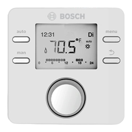
- Page 1 6 720 811 153-00.1O CRC200 Comfort Room Controller Installation instructions for contractors...
-
Page 2: Table Of Contents
9 Troubleshooting ......26 10 Environmental protection/disposal ....28 6 720 821 651 (2017/05) CRC200... -
Page 3: Explanation Of Symbols And Safety Instructions
▶ Install only genuine spare parts. HC assignment HC assignment Electrical work 6 720 811 156-11.1O Table 1 Additional symbols Electrical work may be carried out only by qualified electricians. ▶ Before starting electrical work: CRC200 6 720 821 651 (2017/05) -
Page 4: Product Description
This operation requires additional optional outdoor sensor occur. accessory Room temperature-dependent operations: • supply temperature control • power output control The supply temperature is adjusted using the heating curve in outdoor reset controls ( ) (with or without room 6 720 821 651 (2017/05) CRC200... -
Page 5: 2Possible Applications In Different Heating Systems
HC 1 disinfection are made in heating zone 1 on the CRC200. On the CRC200 for heating zones 2 ... 8, it is possible to set one operating mode for water heating. The heat source selects the 6 720 811 153-03.1O highest value from the set point values received. -
Page 6: Important Instructions For Use
• The user interface may be connected only to heat sources with Bosch EMS-BUS or CZM100 for multi-zone applications. • This user interface is intended only for wall-mounted installation ( Chapter 3, starting at page 7). -
Page 7: Technical Data
If the outdoor reset control is enabled to factor in the room temperature, the room temperature functions as an additional reference variable. The control quality depends on the installation location. CRC200 6 720 821 651 (2017/05) - Page 8 • The user interface must be installed on an interior wall. outdoor temperature dependent control. • Do not place obstructions within 2 1/2' (0.75 m) below CRC200. ≥ 3 1/4' (≥ 1 m) (0.6 m) 6 720 811 153-03.1O Fig. 5...
-
Page 9: Installation
Mounting the base BUS/ Power connection Power is supplied to the user interface via EMS BUS. CRC200 Connections are not polarity specific. If the maximum total length of the BUS connections between all BUS users is exceeded or the BUS system has a ring 6 720 811 156-06.1O... -
Page 10: Attaching Or Removing The User Interface
3. Remove the user interface by lifting upward. 2. Snap the bottom of the user interface into the base. 6 720 809 984-07.1O 6 720 809 984-06.1O Fig. 9 Removing the user interface Fig. 8 Attaching the user interface 6 720 821 651 (2017/05) CRC200... -
Page 11: Controls
▶ Press to return to the higher menu level or discard a changed value. ▶ Hold down to switch from a menu to the standard display. menu button ▶ Press to open the main menu. menu ▶ Hold down to open the service menu. Table 3 Controls CRC200 6 720 821 651 (2017/05) -
Page 12: Commissioning
▶ Press the dial in order to confirm the setting. -or- ▶ If several CRC200 are installed in the system:Turn the dial to assign one of the heating zones 2 to 8 and then press the dial. 6 720 811 156-11.1O The display switches to automatic configuration. - Page 13 ▶ Press the dial to make the flashing default setting appear. ▶ Turn the dial to change the setting. ▶ Press the dial to switch to the next setting. 6 720 811 156-35.2O Table 4 Basic settings CRC200 6 720 821 651 (2017/05)
-
Page 14: Checklist: Important Settings For Commissioning
▶ Turn the dial to select NO and press the dial. The system configuration continues. Upon selecting YES the CRC200 is configured as a controller. The heating system and possibly water heating are operating. Following configuration, only the menu items relevant for the configured system are displayed. -
Page 15: Main Menu
Actual Temp. Sensor calib. Recirculation Contrast Disinfection Service 6 720 821 651-17.1O Fig. 11 Main menu summary Set language. Available only on the user interface for heating zone 1. Service menu ( Chapter 8) CRC200 6 720 821 651 (2017/05) -
Page 16: Service Menu
Set Room Temp Base point Max. Suppl.T. 6 720 821 651-18.2O Fig. 12 Overview of the service menu Available only on the user interface for heating zone 1. Available if supported by heat source. 6 720 821 651 (2017/05) CRC200... -
Page 17: System Data Menu
Heating is off in the entire system at this set outdoor temperature. This (10...30 °C) saves energy at higher outdoor temperatures. (only for heating zone 1) Table 5 Settings in the system data menu CRC200 6 720 821 651 (2017/05) - Page 18 36 (2) St. Louis 0 ( – 18) Miami 36 (2) Toronto – 9 ( – 23) Minneapolis – 20 ( – 29) Washington 0 ( – 18) Table 6 Minimum outdoor temperature for USA 6 720 821 651 (2017/05) CRC200...
-
Page 19: Heating Zone Menu
NO: If the system has more than one heat source installed (e. g. a hybrid system) or a buffer storage tank is installed, this function must be deactivated. Table 7 Settings in the heating zone menu CRC200 6 720 821 651 (2017/05) - Page 20 ▶ Assured frost protection of the system is not possible without an outdoor temperature sensor. Outdoor temperature-dependent settings are only shown with connected outdoor temperature sensor. 6 720 821 651 (2017/05) CRC200...
- Page 21 ( fig 13 and 14, left). The heating curve can be shifted up or down in parallel by matching the set room temperature ( fig 13 and 14, right). CRC200 6 720 821 651 (2017/05)
- Page 22 [4] Parallel shifting of the base curve [1] by increasing the desired room temperature, limited to T = 176 °F (80 °C) VL,max [5] Parallel shifting of the base curve [1] by increasing the reducing room temperature, limited to T = 167 °F (75 °C) VL,max 6 720 821 651 (2017/05) CRC200...
-
Page 23: Function Test Menu
100: System pump for heating zones with valves running at maximum speed. HC Pump 0 (in %) 0 | 100 (in %) 0: Heating pumps not running/zones valves closed (off). 100: Heating pumps running/zones valves open (on). Table 9 Settings in the function test menu CRC200 6 720 821 651 (2017/05) -
Page 24: Info Menu
DHW Operation Water heating active Water heating not active Set DHW Temp 59...176 °F (15...80 °C) Desired hot water temperature DHW Temp. 59...176 °F (15...80 °C) Measured hot water temperature Table 10 Info menu 6 720 821 651 (2017/05) CRC200... -
Page 25: Maintenance Menu
Software version of the heat source controls 2.xx SW controller NFxx.xx User interface software version HC Module SW NFxx.xx CZM100 software version Table 12 System info 1) Not available if a corresponding module is installed. CRC200 6 720 821 651 (2017/05) -
Page 26: Troubleshooting
If a fault cannot be corrected, contact the They are described in the documents for the heat source used. service technician responsible for your area or the nearest Bosch office. Cause or fault description Testing sequence/Cause Measure A11 6004 Solar module wrongly –... - Page 27 1038 Invalid time/date Date/time not yet set Set date/time Prolonged loss of power supply Avoid voltage failures (A61 = Heating zone 1; A68 = Heating zone 8) Table 13 Fault table CRC200 6 720 821 651 (2017/05)
-
Page 28: Environmental Protection/Disposal
Environmental protection/disposal Environmental protection is one of the fundamental company Old appliances policies of the Bosch Group. We regard quality of performance, Old appliances contain resources that should be recycled. economy and environmental protection as equal objectives. The components are easy to separate and the plastics are Environmental protection laws and regulations are strictly marked. -
Page 29: Setup Log (Service Menu/Contractor)
Yes, on mod. LLH Sensor NO YES Recirculation OFF WWSD °F ( °C) Min.outs.temp °F( °C) OFF ON Damping Tight Medium Loose Building Type Table 15 Setup log CRC200 6 720 821 651 (2017/05) -
Page 30: Index
Connection to the heat source ......... 9 – System ..............20 Continuous heating ............19 Frost thresh............19–20 Control type ............... 17 Function module ............7 Controls ..............11, 25 Functional test .............16 Current fault ............... 25 6 720 821 651 (2017/05) CRC200... - Page 31 Thermal disinfection ............ 23 Power connection ............9 Troubleshooting ............26 Power failure ...............14 Power reserve ............4, 14 Product Description ............4 User interface ............. 17 Using as a controller ............4 Recirculation pump ............17 Recycling ..............28 CRC200 6 720 821 651 (2017/05)