Table of Contents
- 1 Table of Contents
- 2 Introduction
- 3 Important Safeguards & Recommendations
- 4 Before Using the Oven for the First Time
- 5 Control Panel
- 6 How to Use the Conventional Oven (Top Oven)
- 7 How to Use the Multifunction Oven (Main Bottom Oven)
- 8 Cooking Advice
- 9 Electronic Programmer
- 10 Cleaning & Maintenance
- 11 Advice for the Installer
- 12 Installation
- 13 Electrical Installation
- 14 Technical Data
Table of Contents

Related Manuals for Kenwood CKBU 300


Summary of Contents for Kenwood CKBU 300
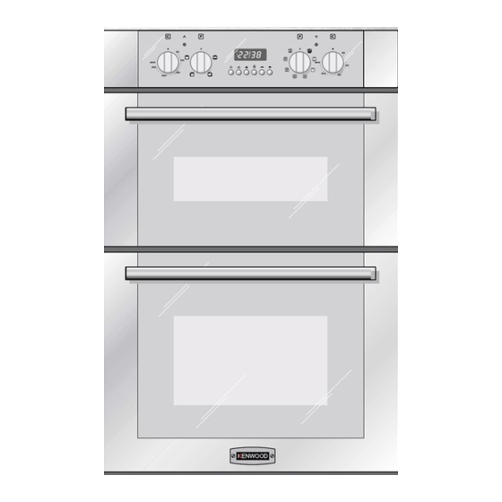
- Page 1 BUILT UNDER DOUBLE OVEN model CKBU 300 Instructions for use - Installation advice Before operating this oven, please read these instructions carefully...
-
Page 3: Table Of Contents
CONTENTS Page Number Introduction ..........4 Important Safeguards &... -
Page 4: Introduction
Dear Customer, Thank you for purchasing a Kenwood CKBU 300 built under double oven. The safety precautions and recommendations in these instructions are for your own safety and that of others. They will also provide a means by which to make full use of the features offered by your appliance. -
Page 5: Important Safeguards & Recommendations
IMPORTANT SAFEGUARDS & RECOMMENDATIONS Do not carry out any cleaning or maintenance without first disconnecting the appliance from the electrical supply. During and after use of the double oven, certain parts will become very hot. Do not touch hot parts. After use always ensure that the control knobs are in the OFF position. -
Page 6: Control Panel
1 - CONTROL PANEL Fig. 1.1 CONTROL PANEL 1. Oven temperature knob (Top oven) 2. Function selector knob (Top oven) 3. Digital electronic programmer (Main oven only) 4. Function selector knob (Main oven) 5. Oven temperature knob (Main oven) 6. Main oven temperature indicator light 7. -
Page 7: How To Use The Conventional Oven (Top Oven)
2 - HOW TO USE THE CONVENTIONAL OVEN (top oven) GENERAL FEATURES OPERATING PRINCIPLES The convection oven is equipped with 3 Heating and cooking in the CONVEN- electrical heating elements: TIONAL oven are obtained in the follow- ing ways: – 2 elements (upper and lower) for nor- mal oven cooking a. - Page 8 Fig. 2.1 Fig. 2.2 TEMPERATURE KNOB (fig. 2.1) To turn on the heating elements of the oven, set the function selector knob to the required position and the temperature knob to the desired temperature. To set the temperature, turn the control knob to line the indicator mark with the required temperature.
- Page 9 LOWER HEATING ELEMENT In this position only the lower element is switched on. Heat is distributed by natural con- vection. The thermostat can be set between 50°C and 250°C; higher temperatures are not available. Recommended for: This mode is particularly suitable to complete cooking of dishes that require higher tem- perature at the bottom.
-
Page 10: How To Use The Multifunction Oven (Main Bottom Oven)
3 - HOW TO USE THE MULTIFUNCTION OVEN (bottom main oven) GENERAL FEATURES OPERATING PRINCIPLES The multi-function oven can be pro- Heating and cooking in the MULTI- grammed for 7 different functions to FUNCTION oven are obtained in the fol- satisfy every cooking need. - Page 11 Fig. 3.1 Fig. 3.2 TEMPERATURE KNOB (fig. 3.2) To turn on the heating elements of the oven, set the function selector knob to the required position and the temperature knob to the desired temperature. To set the temperature, turn the control knob to line the indicator mark with the required temperature.
- Page 12 GRILLING The infra-red heating element is switched on. The heat is diffused by radiation. Use with the oven door closed and the temperature knob set between 50°C and 200°C. For correct use see chapter “USE OF THE GRILL”. Recommended for: Intense grilling action for cooking with the broiler;...
- Page 13 VENTILATED GRILL COOKING The infra-red grill and the fan are on. The heat is mainly diffused by radiation and the fan then distributes it throughout the oven. The temperature must be regulated between 50°C and 175°C with the temperature knob. It is necessary to preheat the oven for about 5 minutes.
-
Page 14: Cooking Advice
COOKING ADVICE GRILLING AND “AU GRATIN” Grilling may be done using the grill+fan setting , in this setting the hot air ROASTING completely surrounds the food that is to To obtain classical roasting, it is neces- be cooked, to give a more even and sary to remember: rapid cooking process. -
Page 15: Electronic Programmer
4 - ELECTRONIC PROGRAMMER (Main oven only) The electronic programmer performs the Description of the illuminated following functions: symbols: – 24 hours clock with illuminated dis- A - flashing: Programmer in automatic play position but not programmed – Timer (up to 23 hours and 59 minutes) A - always illuminated: Programmer in automatic position with program –... - Page 16 MANUAL OPERATION SETTING TIME OF DAY (fig. 4.2) The programmer is provided with an To use the oven manually, i.e. without electronic clock with luminous figures the programmer, you must cancel the showing the hour and minutes. flashing A by pressing the two buttons The first time the oven is connected up simultaneously (the letter A will to the electricity supply and after a...
- Page 17 MINUTE MINDER AUDIBLE SIGNAL The minute counter function consists The audible signal sounds at the end of simply of an acoustic signal which can a minute minder cycle or of a cooking be set for a maximum of 23 hours 59 programme for a period of 7 minute.
- Page 18 The oven will come on immediately and SEMI - AUTOMATIC COOKING when the set time or programmed end of This automatically switches the oven off cooking time expires, it will automatically after the required cooking time. There switch off. are two methods of semi-automatic During cooking the letter A and the sym- cooking: remains on;...
- Page 19 AUTOMATIC COOKING 3. Set the cooking temperature and function via the function selector and To cook in the oven in automatic mode thermostat knob (see specific chap- ters). follow the instructions below: The oven is now programmed and 1. Set the cooking time everything will work automatically;...
-
Page 20: Cleaning & Maintenance
5 - CLEANING AND MAINTENANCE STAINLESS STEEL SURFACES WITH GENERAL ADVICE ANTI-FINGERPRINT TREATMENT Important: Before cleaning or carrying out any CAUTION: maintenance disconnect the appli- The stainless steel front surfaces used in ance from the electrical supply. this oven are protected with a Special Lacquer to reduce finger-print marks. - Page 21 WIRE RACKS – Assemble the wire racks to the oven walls using the 2 screws (Fig. 5.1a - 5.1b). – Slide into the guides, the shelf and the tray (fig. 5.2a - 5.2b). The shelf must be fitted so that the safety stop, which stops it sliding out, faces the inside of the oven.
- Page 22 REPLACING THE OVEN LIGHT Before any maintenance is started involving electrical parts of the appli- ance, it must be disconnected from the power supply. – Let the oven cavity and the heating elements cool down; – Switch off the electrical supply; –...
- Page 23 REMOVING THE OVEN DOOR The oven door can easily be removed as follows: – Open the door to the full extent (fig. 5.4a). – Open the lever “A” completely on the left and right hinges (fig. 5.4b). – Hold the door as shown in fig. 5.4c. Fig.
-
Page 24: Advice For The Installer
Advice for the installer IMPORTANT Appliance installation and maintenance must only be carried out by QUALIFIED TECH- NICIANS and in compliance with the local safety standards. Failure to observe this rule will invalidate the warranty. Always unplug the appliance before carrying out any maintenance operations or repairs. -
Page 25: Installation
6 - INSTALLATION IMPORTANT • The appliance should be installed by a QUALIFIED INSTALLATION TECHNICIAN. The appliance must be installed in compliance with regulations in force. The built under double oven shall be fitted under the working surface into a kitchen base unit (width and depth 60 cm) but you must ensure that it is properly ventilated. - Page 26 INSTALLATION "C" BY USING HOUSING UNIT (figs. 6.3a, 6.3b, 6.3c) • Remove the upper cross member support as indicated in figure 6.3b. • Cut the bottom of the housing as indicated in figure 6.3b. • Screw oven base housing to adjoining cabinetry by suitable screws (not supplied) as indicated in figure 6.3c.
- Page 27 INSTALLATION “A” Fig. 6.1a ( * ) Measure calculated from the underneath of the worktop to the top support base of the “B” supports. WARNING ! VERY IMPORTANT The underside of the cabinet shall be opened to allow correct air circulation. Support base Fig.
- Page 28 INSTALLATION “A” INSTALLATION “B” Pre existing Fig. 6.2a 600 mm cabinetry Fig. 6.2b ( * ) Measure calculated from the underneath of the worktop to the top support base of the “B” supports. WARNING ! VERY IMPORTANT The underside of the cabinet shall be opened to allow correct air circulation.
- Page 29 INSTALLATION “C” ( * ) Measure calculated from the under- neath of the worktop to the top support base of the “B” supports. Cabinet for installing the Remove single oven oven shelf, if fitted. Fig. 6.3b Fig. 6.3a Support base Fig.
- Page 30 Fig. 6.5 Fig. 6.4 IMPORTANT: Fitting the 6 fixing screws to the kitchen base unit. If installing a base panel leave a space as indicated in fig. 6.5 to allow air circulation. Fig. 6.6 KEEP ATTENTION ! STAND AWAY FROM LOUVERS POSI- TIONED BELOW THE CONTROL PANEL.
- Page 31 OVEN DOOR LOWER TRIM AIR FLOW Fig. 6.7 IMPORTANT: To avoid damage to the lower trim please note the following instructions. The lower trim is designed to allow for good air circulation and the correct opening of the oven door. To ensure the trim is not damaged due to the appliance being placed on the floor, the appliance should be suitably supported as in above illustrations.
-
Page 32: Electrical Installation
7 - ELECTRICAL SECTION FEEDER CABLE SECTION Before effecting any intervention Type HO5RR-F or H05VV-F on the electrical parts the appli- ance must be disconnected from the network. 230 V 3 x 2,5 mm (**) (**) – Connection to wall-mounting dis- GENERAL tribution panel. - Page 33 CONNECTING THE DOUBLE OVEN MAINS CABLE – Unscrew the screws A securing the cover plate B behind the oven (fig. 7.1). – Remove the cover plate B. – Remove the screws C from the cable clamp (fig. 7.2). – Insert the mains cable (type H05RR-F or H05VV-F - 3x2,5 mm section) into the cable protector P.
-
Page 34: Technical Data
8 - TECHNICAL DATA Oven lamp 15 Watt - 230V 300°C miniature edison screw Voltage 230V, single phase Total absorbed power 4,06 kW Top oven (Conventional) Top element 700 W Grill element 2000 W Bottom element 1000 W Bottom oven (Multifunction) Top element 900 W Grill element... - Page 35 GUARANTEE UK only If your appliance goes wrong within one year from the date you bought it, we will repair it (or replace it if necessary) free of charge provided: • you have not misused, neglected, or damaged it; • it has not been modified; •...
- Page 36 code 1102740 ß9 Part Number 57676/1...