
Related Manuals for Kenwood CK 304 FS


Summary of Contents for Kenwood CK 304 FS
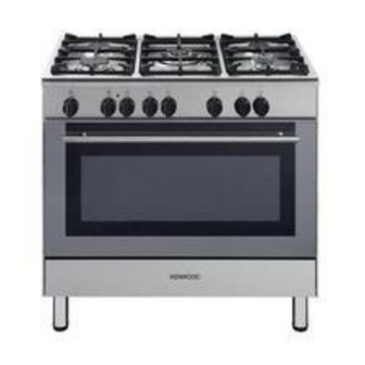
- Page 1 DU L FUEL COOKER K 304 FS Instructions for use - Installation advices Before operating this cooker, please read these instructions carefully...
-
Page 2: Introduction
Dear Customer, Thank you for purchasing a Kenwood Dual Fuel Cooker The safety precautions and recommendations in these instructions are for your own safety and that of others. They will also provide a means by which to make full use of the features offered by your appliance. -
Page 3: Table Of Contents
CONTENTS Page Number Introduction ..........2 - 3 Important Safeguards &... -
Page 4: Important Safeguards & Recommendations
IMPORTANT SAFEGUARDS AND RECOMMENDATIONS After having unpacked the appliance, check to ensure that it is not damaged and that the oven doors close correctly. In case of doubt, do not use it and consult your supplier or a pro- fessionally qualified technician. Packing elements (i.e. - Page 5 • Fire risk! Do not store flammable material in the oven or in the storage compartment. • Make sure that electrical cables connecting other appliances in the proximity of the cooker cannot come into contact with the hob or become entrapped in the oven door. •...
-
Page 6: Cooking Hob
1 - COOKING HOB Fig. 1.1 GAS BURNERS 1. Auxiliary burner (A) 1,00 kW 2. Semi-rapid burner (SR) 1,75 kW 3. Rapid burner (R) 3,00 kW 4. Triple-ring burner (TR) 3,50 kW Note: The electric ignition is incorporated in the knobs. The appliance has a safety valve system fitted, the flow of gas will be stopped if and when the flame should accidentally go out. -
Page 7: Control Panel
2 - CONTROL PANEL Fig. 2.1 CONTROL PANEL - Controls description 1. 120 minutes timer control knob 2. Oven switch knob 3. Oven thermostat knob 4. Front left burner control knob 5. Rear left burner control knob 6. Central burner control knob 7. -
Page 8: Use Of Cooking Hob
3 - USE OF COOKING HOB GAS BURNERS Each burner is controlled by a gas tap which opens and closes the gas supply. Line the control knob symbol up with the indicator on the control panel (fig. 3.1) to obtain: –... - Page 9 LIGHTING GAS BURNERS FITTED CHOICE OF THE BURNER WITH SAFETY VALVE DEVICE On the control panel, near each knob, there is a diagram that indicates which To ignite the burner, the following burner is controlled by that knob. instructions are to be followed: Select the burner that is most suitable for the diameter and capacity of the pan 1) Press in the corresponding knob and...
-
Page 10: Fan Oven
4 - FAN OVEN WARNING: Attention: the oven door becomes The door is hot, use the handle. very hot during operation. ATTENTION - MOST IMPORTANT Keep children away. Pay special attention not to touch the hot heating element inside the oven cavity. - Page 11 THERMOSTAT KNOB (fig. 4.2) HOT AIR COOKING This only sets the cooking temperature and does not switch the oven on. Rotate The circular element and the fan are on. clockwise until the required temperature The heat is diffused by forced convec- is reached (from 50 to 225°C).
- Page 12 COOKING ADVICE SIMULTANEOUS COOKING OF DIFFERENT FOODS STERILIZATION The FAN consents a simultaneous het- Sterilization of foods to be conserved, in erogeneous cooking of different foods. full and hermetically sealed jars, is done Different foods such as fish, cake and in the following way: meat can be cooked together without mixing the smells and flavours together.
-
Page 13: Cooking Guide
5 - COOKING GUIDE Temperature and times given are approximate, as they will vary depending on the quality and amount of food being cooked. Remember to use ovenproof dishes and to adjust the oven temperature during cooking if necessary. COOKING CHART Temperature Food Cooking Time (approx) -
Page 14: Minute Counter
6 - 120 MINUTES TIMER 120 MINUTES TIMER Fig. 6.1) The timer can be set to a maximum of 120 minutes and a buzzer will sound at the end of the countdown. The knob must be rotated clockwise as far as the 120 minutes position first and then set to the required time by rotating it anticlockwise. -
Page 15: Cleaning & Maintenance
7 - CLEANING AND MAINTENANCE GENERAL ADVICE – When the appliance is not being used, it is advisable to keep the gas tap closed. – Every now and then check to make sure that the flexible tube that connects the gas line or the gas cylinder to the appliance is in perfect condition and eventually substitute it if it shows signs of wearing or damage. - Page 16 ENAMELLED PARTS All the enamelled parts must be cleaned with a sponge and soapy water or other non- abrasive products. Dry preferably with a soft cloth. Acidic substances like lemon juice, tomato sauce, vinegar etc. can damage the enamel if left in contact for too long. STAINLESS STEEL, ALUMINIUM PARTS AND SILK-SCREEN PRINTED SURFACES Clean using an appropriate product.
- Page 17 BURNERS CORRECT REPLACEMENT OF THE BURNERS The burners can be removed and washed with soapy water only. It is very important to check that the They will remain perfect if always burner flame distributor F and the cap C cleaned with products used for silver- has been correctly positioned (see figs.
- Page 18 TRIPLE RING BURNER The triple ring burner must be correctly positioned (see fig. 7.3); the burner rib must be enter in their logement as shown by the arrow. The burners must be correctly positioned so that they cannot rotate (fig. 7.4). Then position the cap A and the ring B (fig.
- Page 19 Fig. 7.6 OVEN DOOR STORAGE COMPARTMENT The storage compartment is accessible The internal glass panel can be easily through the pivoting panel (fig. 7.7). removed for cleaning by unscrewing the 4 retaining screws (Fig. 7.6). Do not use harsh abrasive cleaners or sharp metal scrapers to clean the oven door glass since they can Do not store flammable material in...
- Page 20 INSIDE OF OVEN The oven should always be cleaned after use when it has cooled down. The cavity should be cleaned using a mild detergent solution and warm water. Suitable proprietary chemical cleaners may be used after first consult- ing with the manufacturers recommen- dations and testing a small sample of the oven cavity.
- Page 21 OVEN TRAY The oven tray must be correctly placed on the wire support (fig. 7.10) then inserted into the side runners (fig. 7.11). OVEN FLOOR The oven floor “F” (fig. 7.11) can be easily removed to facilitate cleaning. Remember to replace the floor correctly afterwards. Be careful not to confuse the tray “L”...
- Page 22 REMOVING THE OVEN DOOR Fig. 7.12A The oven door can easily be removed as follows: – Open the door to the full extent (fig. 7.12A). – Attach the retaining rings to the hooks on the left and right hinges (fig. 7.12B). –...
-
Page 23: Advice For The Installer
Advice for the installer IMPORT NT – Cooker installation and maintenance must only be carried out by a suitably qualified and registered technician and in compliance with the local safety standards. Failure to observe this rule will invalidate the warranty. –... -
Page 24: Installation
8 - INSTALLATION This cooker has class “2/1” overheating protection so that it can be installed next to a cabinet. The cooker must be installed by a qualified technician and in compliance with local safety standards. If the cooker is installed adjacent to furniture which is higher than the gas hob cooktop, a gap of at least 200 mm must be left between the side of the cooker and the furniture. - Page 25 FITTING THE ADJUSTABLE FEET The adjustable feet must be fitted to the base of the cooker before use. Rest the rear of the cooker on a piece of the polystyrene packag- ing exposing the base for the fit- ting of the feet. Fit the 4 legs by screwing them tight into the support base as Fig.
- Page 26 MOVING THE COOKER WARNING When raising cooker to upright posi- tion always ensure two people carry out this manoeuvre to prevent dam- age to the adjustable feet (fig. 8.5). WARNING Be careful: do not lift the cooker by the door handle when raising to the upright position (fig.
- Page 27 STABILITY BRACKET We recommend a stability bracket is fitted to the cooker. The type shown in fig. 8.8 can be purchased from most plumbers merchants and do it yourself (D.I.Y.) shops. Existing slot in rear of cooker Brackets Fig. 8.8 Dotted line showing the position of cooker when fixed Outline of cooker...
- Page 28 PROVISION FOR VENTILATION – The appliance should be installed into a room or space with an air supply in accordance with BS 5440-2: 2000. – For rooms with a volume of less than 5 m - permanent ventilation of 100 cm free area will be required.
-
Page 29: Gas Section
9 - GAS SECTION IMPORTANT NOTE This appliance is supplied for use on NATURAL GAS or LPG (check the gas regulation label attached on the appliance). – Appliances supplied for use on NATURAL GAS: they are adjusted for this gas only and cannot be used on any other gas (LPG) without modification. - Page 30 GAS CONNECTION The installation of the gas appliance to Natural Gas or LP Gas must be carried out by a suitably qualified and registered installer. Installers shall take due account of the provi- sions of the relevant British Standards Code of Practice, the Gas Safety Regulations and the Building Standards (Scotland)(Consolidation) Regulations issued by the Scottish Development Department.
- Page 31 Gas connection Cat: II 2H3+ The gas supply must use the nearest gas inlet pipe which is located at the left or the right hand side at the rear of the appliance (figs. 9.1 - 9.3). The hose should also be connected in such away that it does not touch the floor. To screw the connecting tube operate with two spanners (fig.
- Page 32 IMPORTANT PRESCRIPTIONS FOR GAS CONNECTION Rear wall Suggested area for gas mains connection Fig. 9.3...
- Page 33 CONVERSION TO LPG / NATURAL GAS 1 - Injectors replacement of top burners If the injectors are not supplied they can be obtained from the “Service Centre”. The diameter is marked on the injector in cents of millimetre. Select the injectors to be replaced according to the “Table for the choice of the injectors”...
- Page 34 TABLE FOR THE CHOICE OF THE INJECTORS Cat: 2H3+ G30 - 28-30 mbar G31 - 37 mbar 20 mbar Nominal Reduced Ø injector Ø injector BURNERS Power Power [1/100 mm] [1/100 mm] [Hs - kW] [Hs - kW] Auxiliary (A) 1,00 0,30 72 (X)
-
Page 35: Electrical Section
10 - ELECTRICAL SECTION WARNING! ELECTRICITY CAN BE EXTREMELY DANGEROUS. THIS APPLIANCE MUST BE EARTHED. The appliance must be connected to the electrical network verifying above all that the voltage corresponds to the value indicated on the specifications plate and that the cables section of the electrical plant can bear the load which is also indicated on the plate. - Page 36 CONNECTION TO FIXED WIRING A double pole switch must be provided no further than 2 metres from the appliance to the electrical supply. The appliance should be connected to a DOUBLE POLE SWITCHED FUSED SPUR OUTLET, similar to that shown in Fig. 10.3. DOUBLE POLE SWITCHED FUSED SPUR OUTLET FUSE...
-
Page 37: Guarantee
GUARANTEE UK only If your appliance goes wrong within one year from the date you bought it, we will repair it (or replace it if necessary) free of charge provided: • you have not misused, neglected, or damaged it; • it has not been modified; •... -
Page 38: After Sales Service
AFTER SALES SERVICE If you require After Sales Service please contact the Currys Product Support Line on 0844 561 6263. Ser. Nr. - Page 39 Descriptions and illustrations in this booklet are given as simply indicative. The manufacturer reserves the right, considering the characteristics of the models described here, at any time and without notice, to make eventual necessary modifications for their construction or for commercial needs.
- Page 40 ode 1103499 ß2...