Table of Contents
SERVICE MANUAL
Ver 1.1 2001. 06
MDR-RF975R is the component model block one in the MDR-RF975RK.
COMPONENT MODEL NAME FOR MDR-RF975RK
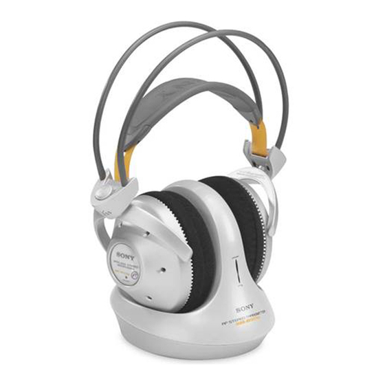
Headphones
MDR-RF975R
Transmitter
TMR-RF975R
Sony Corporation
9-873-141-12
Personal Audio Company
2001F0200-1
Shinagawa Tec Service Manual Production Group
© 2001.6
MDR-RF975R
SPECIFICATIONS
Headphones
Power source
DC 2.4 V: Built-in rechargeable
Mass
Approx. 350 g (12.3 oz.) incl.
built-in rechargeable battery
Built-in Ni-MH rechargeable battery
Model name
NH-AAC
Voltage
1.2 V
Capacity
1,000 mAh
Design and specifications are subject to change without
notice.
battery
US Model
HEADPHONES
Table of Contents

Related Manuals for Sony MDR-RF975R


Summary of Contents for Sony MDR-RF975R
- Page 1 MDR-RF975R SERVICE MANUAL US Model Ver 1.1 2001. 06 MDR-RF975R is the component model block one in the MDR-RF975RK. COMPONENT MODEL NAME FOR MDR-RF975RK Headphones MDR-RF975R Transmitter TMR-RF975R SPECIFICATIONS Headphones Power source DC 2.4 V: Built-in rechargeable battery Mass Approx. 350 g (12.3 oz.) incl.
-
Page 2: Table Of Contents
MDR-RF975R SECTION 1 GENERAL TABLE OF CONTENTS This section is extracted from instruction manual. Specifications ................1 Turn up the volume to a moderate level GENERAL ................. 2 with the VOL control. Press the TUNING button briefly for 2. DISASSEMBLY automatic tuning of the headphones. -
Page 3: Disassembly
MDR-RF975R SECTION 2 DISASSEMBLY • The equipment can be removed using the following procedure . Driver (R side), RX-BASE board SW board, Harger (R) Holder (R) Driver (L side), Hanger (L) Holder (L) Note: Follow the disassembly procedure in the numerical order given . -
Page 4: Sw Board, Hanger (R)
MDR-RF975R 2-2. SW BOARD, HANGER (R) 3 Lid (R), hanger 5 Holder (R) 4 Two screws (P 2 × 8) 8 SW board 2 Housing (R) 7 Remove the two solderings. Precaution for installtion Set the each leads as illustrated below. -
Page 5: Driver (L Side)
MDR-RF975R 2-4. DRIVER (L SIDE) Set the each leads as illustrated below. From head band assy (front). Groove Groove From head Housing (L) band assy (rear). Precaution for installtion 8 Driver 6 Ear pad holder (L) 3 Plate (L) assy, front... -
Page 6: Hanger (L)
MDR-RF975R 2-5. HANGER (L) 5 Holder (L) 3 Lid (L), hanger 2 Housing (L) 4 Two screws (M 2 × 5) Precaution for installtion Set the each leads as illustrated below. 7 Hanger (L) Groove Hanger (L) Groove From head Groove band assy (front). -
Page 7: Electrical Adjustments
MDR-RF975R SECTION 3 Ver 1.1 2001.06 ELECTRICAL ADJUSTMENTS Notes: 12. Set the transmitter CHANNEL switch to 1. 1. Use transmitter with check and adjustment alreadycompleted. 13. Push the headphones tuning switch (S301) to receive radio 2. On adjusting the headphones section, use the transmitter as a frequency. - Page 8 MDR-RF975R Ver 1.1 2001.06 6. Check the waveform of the oscilloscope that the CH1 is demodulated 1kHz signal and CH2 is GND. 7. Connect an AC voltmeter with LPF to speakers terminal (L+L-). 8. Adjust the value of the AC voltmeter to specification by headphones volume RV302.
- Page 9 MDR-RF975R Asjustment Location : IC301 7 (Connect a 33 K Ω resistor) IC301 4 RX-BASE BOARD IC301 6 (Conductor side) RV301: Free Run Frequency Adjustment Short power line (DC 2.4V) L– R– L301: Receive frequency Adjustment RV302: Volume control...
-
Page 10: Diagrams
MDR-RF975R SECTION 4 DIAGRAMS Note on schematic diagrams. Note: • All capacitors are in µF unless otherwise noted. pF: µµF 50 WV or less are not indicated except for electrolytics and tantalums. • All resistors are in Ω and W or less unless otherwise specified. -
Page 11: Block Diagrams
MDR-RF975R 4-1. BLOCK DIAGRAMS RX-BASE BOARD L302 IC307 IF AMP/DECODE (L-CH) IC301 IC308 ANT301 IC309 IC306 (R-CH) Q306 EXPANDER POWER AMP FRONT END FM IF/ DECODE SPEAKER FM FE FE UNIT IC302 DISCRI L-CH R-CH CF301 DETECT IC304 IC305 MUTE... -
Page 12: Schematic Diagram
MDR-RF975R • See page 10 for Notes. • See page 10 for IC Block Diagrams. 4-2. SCHEMATIC DIAGRAM... -
Page 13: Printed Wiring Board
MDR-RF975R 4-3. PRINTED WIRING BOARD • Semiconductor Location RX-BASE BOARD (SIDE A) RX-BASE BOARD (SIDE B) Ref. No. Location ANT301 D301 (ANTENNA) D303 D304 FE UNIT D310 (FRONT-END) IC301 IC302 IC303 IC304 IC305 IC306 IC307 IC308 IC309 Q301 Q303 Q304... -
Page 14: Xplodedviews
MDR-RF975R SECTION 5 EXPLODED VIEWS NOTE: • The mechanical parts with no reference number • -XX, -X mean standardized parts, so they may in the exploded views are not supplied. have some differences from the original one. • Hardware (# mark) list and accessories and •... -
Page 15: Electrical Partslist
MDR-RF975R SECTION 6 ELECTRICAL PARTS LIST RX-BASE Ref. No. Part No. Description Remarks Ref. No. Part No. Description Remarks NOTE: • Due to standardization, replacements in the • CAPACITORS: • SEMICONDUCTORS uF: µF parts list may be different from the parts In each case, u: µ, for example:... - Page 16 MDR-RF975R Ver 1.1 2001.06 RX-BASE Ref. No. Part No. Description Remarks Ref. No. Part No. Description Remarks R320 1-216-001-00 METAL CHIP 1/10W < CERAMIC FILTER > R321 1-216-053-00 METAL CHIP 1.5K 1/10W R322 1-216-069-00 METAL CHIP 6.8K 1/10W CF301 1-577-588-11 FILTER, CERAMIC...
- Page 17 MDR-RF975R RX-BASE RX-SW Ref. No. Part No. Description Remarks Ref. No. Part No. Description Remarks R397 1-216-083-00 METAL CHIP 1/10W R398 1-216-073-00 RES-CHIP 1/10W R399 1-216-073-00 RES-CHIP 1/10W R400 1-216-025-11 RES-CHIP 1/10W R401 1-216-025-11 RES-CHIP 1/10W R403 1-216-073-00 RES-CHIP 1/10W...
- Page 18 MDR-RF975R REVISION HISTORY Clicking the version allows you to jump to the revised page. Also, clicking the version at the upper right on the revised page allows you to jump to the next revised page. Ver. Date Description of Revision 2001.06...