Table of Contents
Quick Links
MDR-RF915R/RF945R
QQ
3 7 63 1515 0
SERVICE MANUAL
Ver 1.0 2001. 05
MDR-RF915R is the component model block one in the MDR-RF915RK.
MDR-RF945R is the component model block one in the MDR-RF945RK.
COMPONENT MODEL NAME FOR MDR-RF915RK/
MDR-RF945RK
Wireless Stereo Headphones MDR-RF915R
TE
L 13942296513
Transmitter
www
.
9-873-137-11
Sony Corporation
Personal Audio Company
2001E0200-1
Shinagawa Tec Service Manual Production Group
© 2001.5
http://www.xiaoyu163.com
MDR-RF915RK MDR-RF945RK
MDR-RF945
TMR-RF915R
TMR-RF945
Headphones
Power source
battery
Mass Approx.
Built-in Ni-Cd rechargeable battery
Model name
Voltage
Capacity
Design and specifications are subject to change without
notice.
x
ao
u163
y
i
http://www.xiaoyu163.com
2 9
8
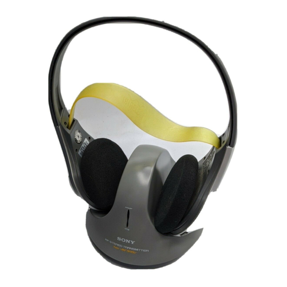
Photo : MDR-RF945R
Q Q
3
6 7
1 3
1 5
SPECIFICATIONS
DC 2.4 V: Built-in rechargeable
240 g (8.5 oz.) incl.
built-in rechargeable battery
NC-AA
1.2 V
700 mAh
co
.
9 4
2 8
US Model
Canadian Model
0 5
8
2 9
9 4
2 8
m
HEADPHONES
9 9
9 9
Table of Contents

Related Manuals for Sony MDR-RF915R


Summary of Contents for Sony MDR-RF915R
- Page 1 SERVICE MANUAL US Model Canadian Model Ver 1.0 2001. 05 Photo : MDR-RF945R MDR-RF915R is the component model block one in the MDR-RF915RK. MDR-RF945R is the component model block one in the MDR-RF945RK. COMPONENT MODEL NAME FOR MDR-RF915RK/ MDR-RF945RK MDR-RF915RK MDR-RF945RK...
-
Page 2: Table Of Contents
MDR-RF915R/RF945R 3 7 63 1515 0 TABLE OF CONTENTS Specifications ................1 3-5. Free Run Frequency Check and Adjustment (MRD-RF945R) ..6 1. GENERAL ............... 2 3-6. Receive Frequency Check and Adjustment (MRD-RF945R) ..6 2. DISASSEMBLY 3-7. Carrier Modulation Check (MRD-RF945R) ....6 3-8. -
Page 3: Disassembly
MDR-RF915R/RF945R SECTION 2 3 7 63 1515 0 DISASSEMBLY • This set can be disassembled in the order shown below. 2-1. RX-BASE BOARD 1 Five screws (P 2 × 6) Cover (R), hanger Claw q; Switch, push (1 key) 9 Remove the two solderings. - Page 4 MDR-RF915R/RF945R 3 7 63 1515 0 Set the lead wires Set the each lead wires as illustrated below. Cover (R), hanger Cover (L), hanger No.201, No.203 Groove Groove No.203 No.201 Groove No.205 Groove No.201 No.203 Groove No.204 No.202 No.202 Groove To the driver (030F032).
-
Page 5: Electrical Adjustments
MDR-RF915R/RF945R SECTION 3 ELECTRICAL ADJUSTMENTS 3 7 63 1515 0 MRD-RF915R Notes: Setting : 1. Use transmitter with check and adjustment alreadycompleted. OSCILLOSCPE 2. On adjusting the headphones section, use the transmitter as a jig. Headphones:MDR-RF915R Transmitter:TMR-RF915R IC301 pin6 IC301 pin4 –... -
Page 6: Carrier Modulation Check (Mrd-Rf945R)
MDR-RF915R/RF945R 3 7 63 1515 0 MRD-RF945R Notes: 12. Set the transmitter CHANNEL switch to 1. 1. Use transmitter with check and adjustment alreadycompleted. 13. Push the headphones tuning switch (S301) to receive radio 2. On adjusting the headphones section, use the transmitter as a frequency. - Page 7 MDR-RF915R/RF945R 3 7 63 1515 0 17. Check the difference of the L and R to more than 20 dB. Digital voltmeter OSCILLOSCPE (AC range) L+ / R+ IC301 pin4 L– / R– – L– – – Asjustment Location :...
-
Page 8: Diagrams
MDR-RF915R/RF845R SECTION 4 DIAGRAMS 4-1. BLOCK DIAGRAMS 3 7 6 3 1 5 1 5 0 RX-BASE BOARD L302 IF AMP/DECODE IC301 ANT301 POWER AMP FRONT END FM IF/ DECODE SPEAKER FM FE IC302 FE UNIT DISCRI R-CH L-CH... -
Page 9: Schematic Diagram
MDR-RF915R/RF845R 4-2. SCHEMATIC DIAGRAM 3 7 6 3 1 5 1 5 0 1 3 9 4 2 2 9 6 5 1 3 • IC BLOCK DIAGRAMS Note on schematic diagrams. Note: • All capacitors are in µF unless otherwise noted. pF: µµF 50 WV or less are not indicated except for electrolytics and tantalums. -
Page 10: Printed Wiring Board
MDR-RF915R/RF845R 4-3. PRINTED WIRING BOARD 3 7 6 3 1 5 1 5 0 RX-BASE BOARD (SIDE A) RX-BASE BOARD (SIDE B) ANT301 (ANTENNA) FE UNIT (FRONT-END) RF945R RF945R RF945R 1 3 9 4 2 2 9 6 5 1 3... -
Page 11: Exploded Views
MDR-RF915R/RF945R SECTION 5 EXPLODED VIEWS 3 7 63 1515 0 NOTE: • The mechanical parts with no reference number • -XX, -X mean standardized parts, so they may in the exploded views are not supplied. have some differences from the original one. -
Page 12: Electrical Parts List
MDR-RF915R/RF945R SECTION 6 ELECTRICAL PARTS LIST RX-BASE 3 7 63 1515 0 Ref. No. Part No. Description Remarks Ref. No. Part No. Description Remarks NOTE: • Due to standardization, replacements in the • CAPACITORS: • SEMICONDUCTORS uF: µF parts list may be different from the parts In each case, u: µ, for example:... - Page 13 MDR-RF915R/RF945R RX-BASE 3 7 63 1515 0 Ref. No. Part No. Description Remarks Ref. No. Part No. Description Remarks IC303 8-759-453-43 IC TC74HC4024AF (RF945R) R341 1-216-113-00 METAL CHIP 470K 1/10W IC304 8-759-510-73 IC BA10393F-E2 (RF945R) (RF945R) IC305 8-759-083-94 IC TC7W74FU (RF945R)
- Page 14 MDR-RF915R/RF945R 3 7 63 1515 0 REVISION HISTORY Clicking the version allows you to jump to the revised page. Also, clicking the version at the upper right on the revised page allows you to jump to the next revised page.